

Translate this page into:
Three-dimensional modelling of gas-air mixture combustion process
⁎Corresponding author. gokhakam@gmail.com (Gaukhar A. Kamalova)
-
Received: ,
Accepted: ,
This article was originally published by Elsevier and was migrated to Scientific Scholar after the change of Publisher.
Peer review under responsibility of King Saud University.
Abstract
Study of high temperature flows is a rather complicated process. So, the objective of the paper is concluded in spatial modelling of gas-air mixture combustion at lateral injection of gas mixture into the canal from the rectangular hole. The authors suggested numerical model of spatial combustion of turbulent flows in a canal with a complicated configuration. In order to model a multi-component flow the authors used Reynolds averaged Navier-Stokes equations, enclosed with turbulence model. The velocities of chemical reactions are rather high, which allows describing these processes with source terms in the equations of the mass and energy balance. The numerical model is based on the control volume approach. The regularities of the flows were investigated in their dependence on the jet operating conditions. The results were compared with the calculations of the other authors. The behaviors of the velocities, temperature and concentration of gas components are set for the combustion and non-combustion conditions. The structures of the combustion zone are defined and investigated in the spatial canal with partially opened boundary, as well as influence of the operating conditions on the ignition behavior.
Keywords
Turbulence
Multicomponent mixture
Temperature field
Control volume approach
Computational mesh
Chemical reaction
Jet parameter

1 Introduction
Development of the turbulent multi-component flow theory provided an opportunity to approach the problem of modelling and research of high temperature flows. The complexity of the considered problem is connected with the incompleteness of the turbulence theory and with the peculiarities of turbulent flows at presence of chemical reactions, concluded in extremely complicated character of mutual influence of the turbulent transfer processes and the processes of chemical response. Study of the combustion processes including definition of the fields of velocities, temperatures, component concentration considering the kinetics of the process, definition of the mixture zone boundary, shape of the flare and the flow character is rather complicated both for experimental research and in the context of mathematical modelling.
The problems of homogenous gas and air mixture combustion are rather elaborately described in a series of papers (Bagheri et al., 2014; Schultze et al., 2013; Amzin and Swaminathan, 2013; Schultze and Mantzaras, 2013; Hosseini and Wahid, 2014; Goodarzi et al., 2015; Liberman, 2003; Langella et al., 2015), among which the most well-known models of diffusive turbulent combustion are presented in papers (Amzin and Swaminathan, 2013; Bagheri et al., 2014; Schultze et al., 2013; Schultze and Mantzaras, 2013; Rosa et al., 2018). Extensive review of the papers devoted to homogenous flow of the reacting gas mixtures is presented in Khodjiyev (1994), while the issues of numerical modelling of turbulent flare are also considered in Schlichting and Gersten (2017). These papers contain the modelling of problems of non-mixed gases turbulent combustion process in two-dimensional setting based on the system of Navier-Stokes parabolic equations (Khodjiyev, 1994) and the system of boundary-layer equations (Aliyev and Zhumayev, 1987; Schlichting and Gersten, 2017).
The problem of adequate description of reacting multi-component gas mixtures flows is connected with the presence of additional source terms, included into the equations of the components’ mass and energy, which in their turn lead to the problem of ensuring stability of the numerical calculation.
Gas mixtures combustion processes ongoing in the irregular shape structures, where the domain is limited, require the use of Navier-Stokes equations, enclosed by some or other turbulence model. Paper (Stankov and Toporov, 2001) is notable, where based on the averaged Navier-Stokes equations three-dimensional turbulent reacting gas mixtures flow in combustion installation is modelled. However, this paper mostly contains test calculations and there is almost no numerical research of influence of such practically important parameters as velocity, temperature of air mixture (or gas mixtures) and concentration of the components.
That is why the objective of this work is in spatial modelling of gas-air mixture combustion at lateral injection of the gas mixture into the canal from the rectangular hole.
2 Analysis of turbulent jet flow patterns
We consider spatial flow of gas mixture turbulent jet
, flowing from the rectangular jet pipe into the three-dimensional canal. The scheme of the flows is shown at Fig. 1.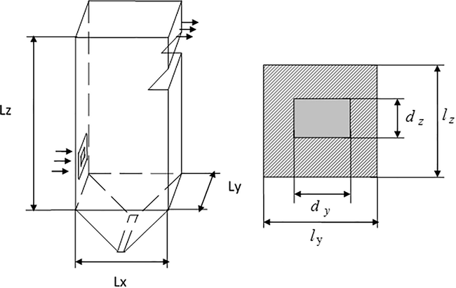
Scheme of the canal and combustion arc.
Alongside with the set task we also consider turbulent three-dimensional flow of reacting gas mixture, where it is suggested that the velocities of the chemical reactions are rather high, which allows describing these processes with source terms in the equations of the mass and energy balance.
At the same time, the initial equations of multi-component reacting gas mixtures of turbulent flow are as follows:
Here: ,
Additional members in Eqs. (2), (4), conditioned with velocities of the chemical reactions are as follows:
Definition of the chemical reaction velocity is presented below.
To enclose the initial system of equations
turbulence model is used, the invariables of which are set in the Table 1 as follows.
0.09
1.44
1.92
−1.0
1.0
1.3
1.5
3 Characteristics of initial and boundary conditions
In the initial moment the gas is at a standstill, the densities of the components are set, distribution of the temperature is constant, and kinetic energy of turbulence and the scale of turbulence
are also invariable:
At the inlet: inside of the jet pipe – gas mixture
In the external part of the pipe – oxidizer, i.e. diluent air
, , , , , , .
At the walls: for the field of velocity we set the turbulent rule of the wall, tangential component of velocities, which are defined by approximate relationships, obtained through logarithmic profile and wall rule the same as in paper (Zeldovich and Voyevodsky, 2005):
And for the temperature field:
For kinetic energy of turbulence and concentrations of the gas components there is a condition of no-flow through the wall:
Connection between the kinetic energy of turbulence and the velocity of its dissipation are set.
Soft boundary conditions are set at the outlet:
4 Kinetics of combustion chemical reaction
Each chemical reaction takes place according to the rule of constant definite proportions and in its general view it is inscribed as stoichiometric equation:
Stoichiometric coefficients of direct and reverse reaction
and
should comply with the following condition:
In order to keep the mass action law and chemical reaction.
The basic correlation describing the velocity of chemical reaction is the correlation set by the mass action law. In accordance with the mass action law, the velocity of chemical substance formation is proportional to the multiplication of the reacting components’ concentrations. The velocity of kinetic reaction is set from paper (Amsden et al., 1989):
Expressions for the invariables of the chemical reactions’ velocities are defined according to Arrhenius equation:
Description of gas components
chemical reaction with the air is carried out on the basis of chemical model (Table 2).
Number of reaction
Reaction
1
2
3
4
5
6
Thus, the model of chemically reacting gas used in the paper includes nine components: . As seen from Table 2, overall reactions are considered, which constituent subsequence from a greater number of elementary reactions (Kamalova et al., 2008).
Definition of Chemical Reaction Velocity. According to paper (Amsden et al., 1989), the velocity of chemical reaction is calculated from the proposition that for reaction each participating component is either inert ( ), or appears only at one side of reaction ( ).
Let us write down the value of the chemical reaction velocity (19) as follows:
where , .
Then the growth of mass
from (10) will be as follows:
Next, let us preliminarily check the components, the number of which decreases in accordance with the considered reaction, in order to define the component with the minimum value , and assign it index , i.e. . Thus, this expression is the most critical from the total of the chemical reaction velocities income, which may lead to negative value of density.
Thereafter let us calculate the change in the characteristic mixture component
:
or:
Let us insert the following designations:
Considering it (24) we will have the following:
After linearization the Eq. (25) is as follows:
From which it appears:
If to consider that Eq. (23) is also written down as follows:
together with equation
in (26), then the chemical reaction velocity is defined as follows:
Thus, in the members, conditioned by the chemical reactions (10), the reaction velocity will be defined by the linearized expression (27).
5 Analysis of the study results
The set task was solved by means of the algorithm set out in Kamalova (2009), Kamalova and Naimanova (2005), Xiao (2016), Fan et al. (2014). The number of the control volumes is equal to 127,756.
The numerical calculation was carried out at the following values of the characteristic parameters: , . Height of the canal width Lx 1 m, depth Ly 0.5 m. The rectangular hole has the following size: for gas components (internal) , for diluent air, i.e. oxidizer (external) .
The initial data: kinetic energy of turbulence
, length scale
The composition of the injected gas components is presented in Table 3.
Variant
Gas Components
1
0.11
0.041
0.411
0.017
0.421
Let us demonstrate the results of the calculations.
Fig. 2A shows the fields of the velocity vector in vertical (Fig. 1Aa) and horizontal (Fig. 2Ab) jet mirror plane (plane
is meant by the jet mirror plane, located in the central section of the jet for
). As seen from Fig. 2Aa, in the three-dimensional case the quality picture of the section field in the vertical plane is the same as the two-dimensional one (formation of vortex zones, both in the upper and the lower jet part). Comparison of these two pictures shows that the intensity of the vortex zones in the three-dimensional case is lower. It is explained by presence of additional lateral spreading of the jet (Fig. 2Ab). Fig. 2Ab shows that at horizontal spreading of the jet small dead spaces are also formed near the area adjacent to the jet.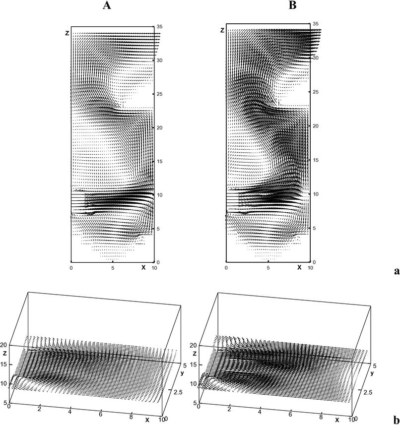
Fields of velocity vector in vertical (a) and horizontal (b) planes of the jet symmetry. A – absence of combustion; B – presence of combustion.
General picture of the velocity field vector (in planes and of the jet symmetry) of reacting gas mixture is also unchangeable, as is shown at Fig. 2B, one may observe only acceleration of the flow, significant at the combustion area.
The ignition area is well defined by the curves of the finished reaction products, i.e. dioxide carbon
(Fig. 3, in plane
). The Figure shows that in the jet symmetry plane in the area of intensive mixing of the gas mixture with the jet at some distance from the pipe section, the ignition starts having the shape peculiar to flare (Fig. 3a). In the domain below the injected jet the combustion area adjusts to the external wall (Fig. 3b–c), while in the upper part of the canal the combustion area is shifted from the wall due to the flow turning (Fig. 3d–e).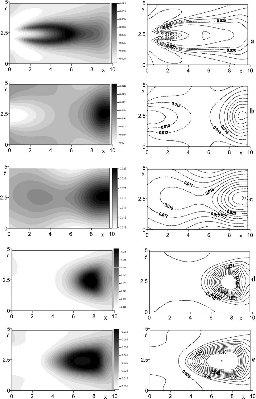
Distribution of the finished product
concentration along the horizontal sections. a)
(jet symmetry plane); b)
(below the jet); c)
(below the jet); d)
(above the jet); e)
(above the jet).
Shift of the combustion area in the vertical plane is also well seen from Fig. 4, where
contour lines are presented along the cross section areas.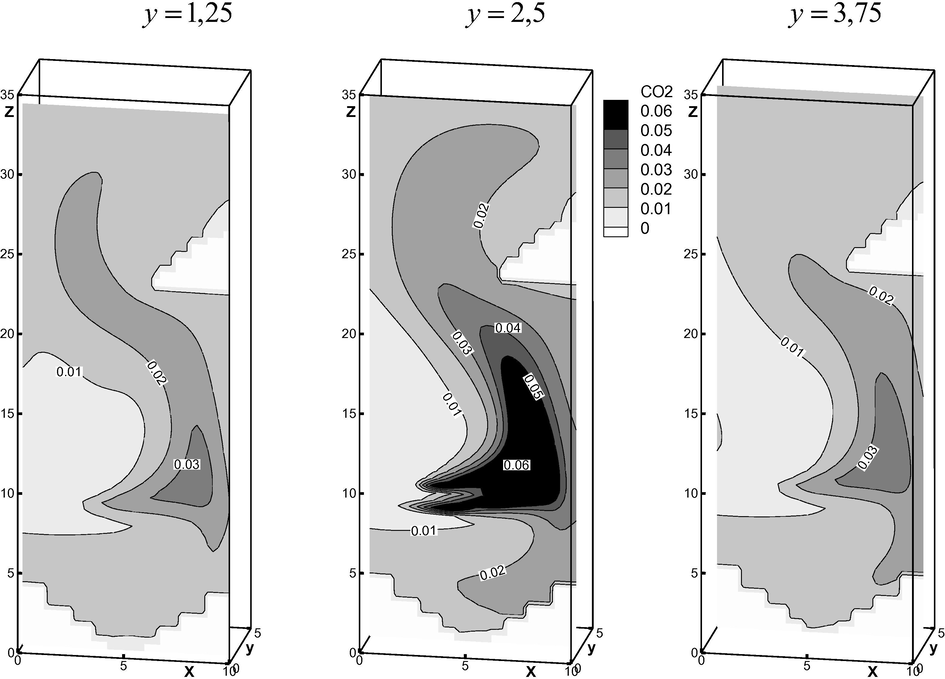
Distribution of the finished product
concentration along the vertical sections.
The results of the numerical experiment (Stankov and Toporov, 2001) are presented at Fig. 5, where
is injected, and chemical reaction between methane and the oxidizing agent is considered. As seen from the pictures, maximum value of the temperature reaches
, concentration of the finished product
is
. The agreement of the calculation results with this paper is based on the graphs. Due to the lack of some characteristic values, the numerical calculations do not allow performing quantitative comparison.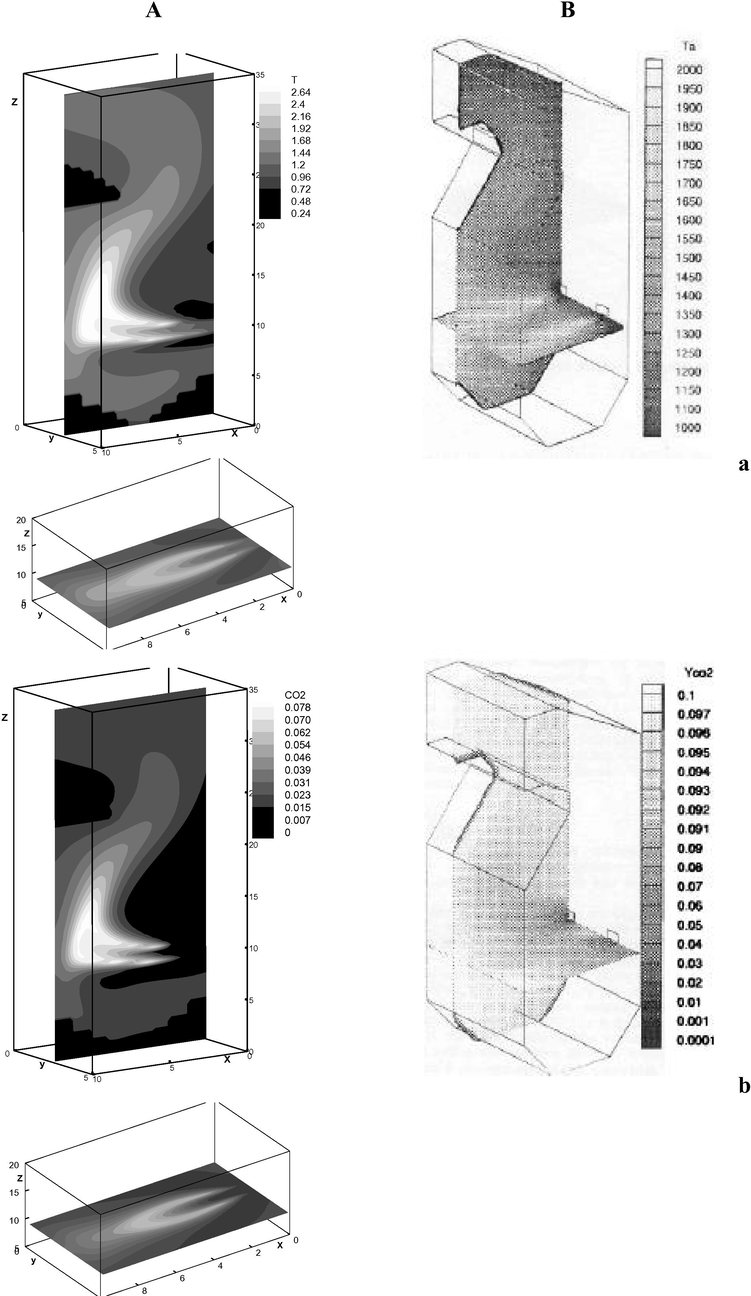
Distribution of temperature (a) and concentration
(b) in the planes of vertical and horizontal symmetry of the jet. A – author’s calculations; B – numerical calculation from paper (Stankov and Toporov, 2001).
Notably, the presented comparison is of qualitative nature, because in paper (Stankov and Toporov, 2001) the considered domain has two holes, i.e. the gas mixture is injected from two pipes and as it was already noted, there is not enough data on the main characteristic parameters. Fig. 5 shows that the combustion area is observed (Fig. 5a) as well as the formed finished product of carbon dioxide (Fig. 5b).
Influence of the outlet value of the diluent air velocity on the characteristics of ignition was studied with the velocity ratio in the range of , i.e. the oxidizing agent outflow velocity (diluent air) varied from 0 to 15 m/s.
Graphs 6a-g (in the plane of the jet symmetry) show that for the ignition zone assumes protruded U-shape, while in the range of with the increase in the velocity ratio the U-shape shortens, but becomes wider.
Thus, the
configuration evidences that for
the length of the “flare” reaches the right wall (Fig. 6b–d), while further increase in
leads to the decrease of the combustion area (Fig. 6e–g), which complies with the numerical calculations of Khodjiev (1994) and experimental data in the papers by Aliyev and Zhumayev (1987), presented for the flare in the concurrent flow.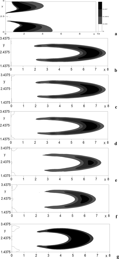
Area of intensive
emission at various parameters of velocity ratio in the horizontal plane of jet symmetry. a)
; b)
; c)
; d)
; e)
; f)
; g)
.
Influence of the diluent air velocity on the process of combustion may also be observed from the line of maximum values of the flow parameters, where at Fig. 7 there are maximums of velocity, temperature and concentration of the finished product depending on
. Increase in the velocity ratio parameter leads to the undulating changes of the longitudal velocity maximum. Influence of
on the maximum of temperatures and concentration of
is insignificant.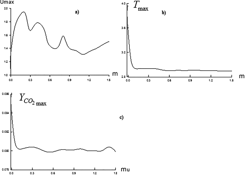
Maximum values of velocity (a), temperature (b), and concentration of the finished product
(c) at various parameters of velocity ratio
.
Numerical research of influence of the diluent air temperature inlet value on the combustion process was conducted for the range of , i.e. for .
As known, in the theory of gas flare, heating of the combustible and oxidizing agent leads to insignificant prolongation of the flare. As the calculation experiment shows (Fig. 8), at small values of parameter
the picture of the temperature field is the same as the gas flare temperature distribution. It is seen that at the increase in parameter
, the external wall retains prolongation of the combustion area, forcing it to go upwards, which leads to its significant vertical expansion (Fig. 7Bc, in the plane
of the jet symmetry). As is shown by the numerical calculations, changes in
to a lesser extent influence the dynamic characteristics.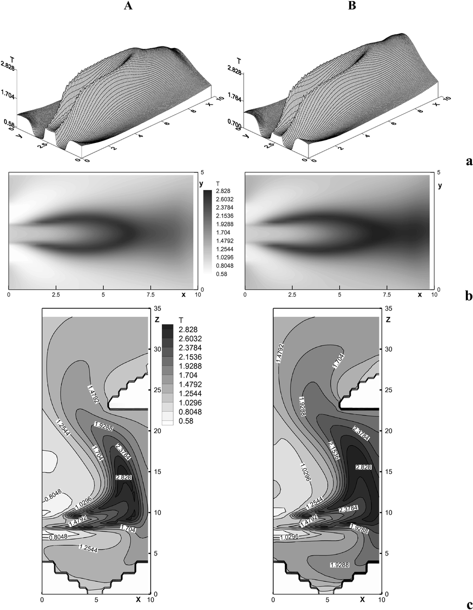
Temperature distribution at various parameters of temperature
in the horizontal (a-b) and vertical (c) planes of the jet symmetry. a)
; b)
; c)
; A)
; B)
.
The analysis of influence shows that the change in the temperature parameter to a significantly lesser extent affects the maximum values of concentration than expansion of the formation area.
Thus, at the injection of the heated diluent air into the limited space, distribution of the flare upwards significantly depends on the horizontal distance from the jet pipe section to the external wall.
Below there are the results of the calculation experiment of influence of the injected gas mixture injection on the parameters of diffusive combustion. It is supposed that the gas mixture is diluted with inactive gas
in the proportions shown in Table 4. The mass concentrations of the rest of the gases comply with the data of Table 3.
Gas Components
Variant
1
2
3
4
0.024
0.085
0.15
0.20
0.507
0.446
0.381
0.331
Dependency of the flare area on the initial concentration of the gas components is presented at Figs. 9–12. As one may observe on the graphs, the initial value of the injected
concentration influenced the thermodynamical jet parameter. So, for example, presence of large amount of methane in the injected gas mixture causes not only expansion of the intensive heat emission zone (Fig. 9a–e, in the plane
), but also nonlinear increase in the maximum temperature value, which is seen at Fig. 10, where the maximum temperature values are presented at various concentrations of the injected
. It is notable that the influence of the gas composition on the dynamical zone of the shift is not very significant.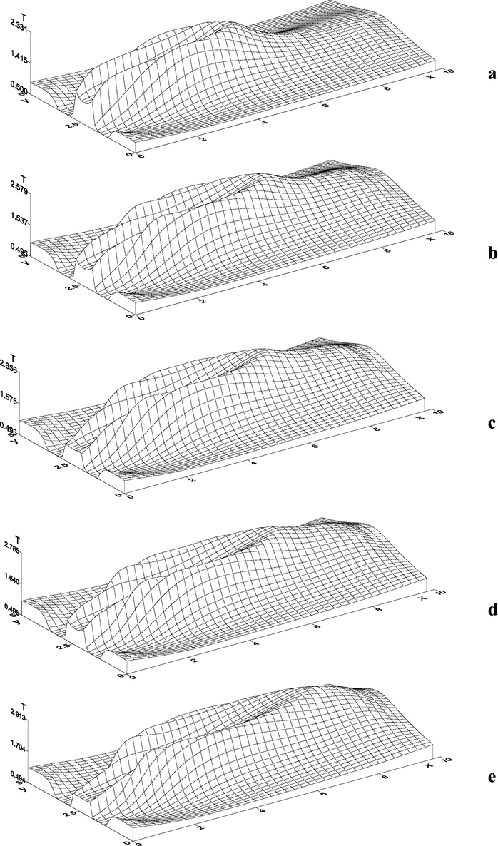
Distribution of temperature at different concentrations of injected
in the horizontal plane of the jet symmetry. a)
; b)
; c)
; d)
; e)
.
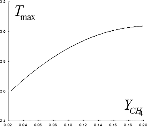
Maximum temperature values at different concentrations of the injected
.
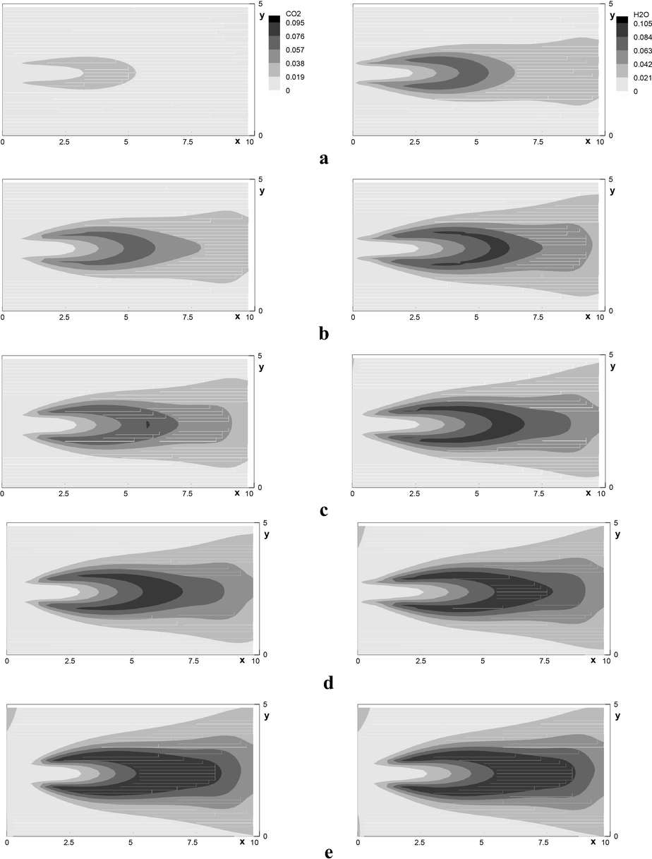
Concentration of finished products
and
at different concentrations of the injected
in the horizontal plane of the jet symmetry. a)
; b)
; c)
; d)
; e)
.
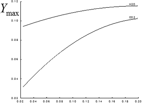
Maximum values of finished combustion products concentration at various concentrations of the injected
.
Emission of the finished combustion products and , their maximum values for various is shown at Fig. 11 (in the plane ) and 12. It is seen that the increase in the methane concentration leads to nonlinear growth of the carbon dioxide and water vapor concentration (Fig. 12).
6 Conclusion
Analysis of the conducted research shows that due to the change in the gas components concentration one may achieve regulation of the combustion configuration within a wider range compared with the change in the velocity and temperature of the diluent air. For example, at the increase in the inlet values and concentration the length of the combustion zone expands, while the maximum concentration of the finished combustion product significantly increases at greater values of the concentration.
We have defined the velocity ratio influence on the thermodynamical characteristics of the flow at the injection of the gas mixture from the internal rectangular hole and diluent air from the external jet pipe.
It has also been revealed that the diluent air, on one hand, expands like a jet in the limited space, while, on the other hand, it compresses the injected gas mixture. At small geometric parameters of the domain, the injected gas mixture collapses, which leads to the change in the combustion zone.
It is shown that due to the change in the gas components concentration one may achieve regulation of the combustion configuration in wider limits, compared to those at the change in the velocity and the diluent air temperature.
Acknowledgement
We express deep gratitude to our academic supervisor Doctor of Physical and Mathematical Sciences, Professor Altynshash Zh. Naimanova for the support and assistance.
Conflict of interest
The authors declare that they have no conflict of interests.
References
- Aliyev, F., Zhumayev, Z.Sh., 1987. Jet Flows of Reacting Gases. Fan, Tashkent.
- KIVA-II: A Computer Program for Chemically Reactive Flows with Sprays. Los Alamos: Los Alamos National Laboratory; 1989.
- Computations of turbulent lean premixed combustion using conditional moment closure. Combust. Theor. Model.. 2013;17(6):1125-1153.
- [Google Scholar]
- Effects of bluff body shape on the flame stability in premixed micro-combustion of hydrogen-air mixture. Appl. Therm. Eng.. 2014;67(1–2):266-272.
- [Google Scholar]
- Effect of bluff body shape on the blow-off limit of hydrogen/air flame in a planar micro-combustor. Appl. Therm. Eng.. 2014;62(1):13-19.
- [Google Scholar]
- Investigation of nanofluid mixed convection in a shallow cavity using a two-phase mixture model. Int. J. Therm. Sci.. 2015;75:204-220.
- [Google Scholar]
- Investigation of bluff-body micro-flameless combustion. Energy Convers. Manage.. 2014;88:120-128.
- [Google Scholar]
- Kamalova, G.A., 2009. Numerical Modelling of Gas Flow with Solid Particles in the Irregular Configuration Domain (Ph.D. Thesis), Almaty.
- Mathematical modelling of gasodynamic processes of biphasic medium in the devices of different configuration. Mathematical J.. 2005;1:52-66.
- [Google Scholar]
- Modelling of turbulent reacting flows in furnace devices. Thermophys. Aeromech.. 2008;15(1):149-161.
- [Google Scholar]
- Khodjiyev, S., 1994. Mathematical Modelling of Heat and Mass Exchange Processes of Internal and External Spatial Turbulent Jets of Reacting Gases (PhD Thesis), Tashkent.
- Assessment of dynamic closure for premixed combustion large eddy simulation. Combust. Theor. Model.. 2015;19(5):628-656.
- [Google Scholar]
- Liberman, M., 2003. Flame, detonation, explosion – when, where and how they occur. Third International Disposal Conference, Karlskoga, Sweden, pp. 5–23.
- Treatment of lubricating oil used with the use of solvents and adsorbent materials. Periódico Tchê Química.. 2018;15(30):127-139.
- [Google Scholar]
- Boundary-Layer Theory. Berlin, Heidelberg: Springer-Verlag; 2017.
- Hetero-/homogeneous combustion of hydrogen/air mixtures over platinum: Fuel-lean versus fuel-rich combustion modes. Int. J. Hydrogen Energy. 2013;38(25):10654-10670.
- [Google Scholar]
- An experimental and numerical investigation of the hetero-/homogeneous combustion of fuel-rich hydrogen/air mixtures over platinum. Proc. Combust. Inst.. 2013;34(2):2269-2277.
- [Google Scholar]
- Stankov, P., Toporov, D., 2001. Modelling of turbulence-chemical reactions interaction in industrial furnace using an advanced model. In: Sixth International Conference on Technologies and Combustion for Clean Environment, Porto, Portugal, pp. 489–494.
- Experimental and Numerical Study of Dynamics of Premixed Hydrogen-Air Flames Propagating in Ducts. Berlin, Heidelberg: Springer; 2016.
- The effects of non-uniform temperature distribution on the ignition of a lean homogeneous hydrogen–air mixture. Proc. Combust. Inst.. 2005;30(1):875-882.
- [Google Scholar]


