

Translate this page into:
Projectile motion revisited: Does the distance between the launcher and the object always increase?
⁎Corresponding author at: Applied Physics Department, Faculty of Computer Science Engineering, University of Castilla-La Mancha, Avda de España s/n, Campus Universitario, 02071 Albacete, Spain. enrique.arribas@uclm.es (Enrique Arribas)
-
Received: ,
Accepted: ,
This article was originally published by Elsevier and was migrated to Scientific Scholar after the change of Publisher.
Peer review under responsibility of King Saud University.
Abstract
In this paper, we have shown that parabolic motion from a critical launch angle has an unexpected property related to the distance between the object and the launcher. This distance decreases in a time interval that occurs between two moments: one, in which distance has a maximum and another in which it has a minimum. As it will be shown, this only happens in launch angles greater than , that is . The launch we have studied occurs from the ground and we have not taken into account air friction. We have not considered the possible variations in the acceleration of gravity, that is, we have taken it as a constant throughout the movement of the projectile. We have used dimensionless coordinates so that the focus is on the angular variable. In addition, at the end of the study, we have used polar variables to visualize what happened. This is a very didactic approach, which can be used in the first year of STEM university degrees. It will also prove useful for teachers that wish to explain parabolic motion in their classes.
Keywords
Active physics
Motion in two dimensions
Kinematics
Parabolic motion
STEM

1 Introduction
When we look at baseballs and tennis balls flying through the air, in a home run hit or a field goal kick, the balls follow a particular curved path through the air, exhibiting what we call projectile motion. Parabolic motion has been extensively studied over the years (Bajc, 1990; Bose, 1985; Lucie, 1979; Medina, 1978; Siegel, 2017; Tan and Giere, 1987). We believed that everything about its characteristics was known, but we have found a new and surprising occurrence.
When we launch a projectile, the particle appears to be constantly moving away from the launcher, both when we look at it from the perspective of the launcher and when we look at it from a position external to the launcher. In this work, we will show that this is not always the case as strange as it may sound. In fact, there are intervals in which the projectile approximates the launch point.
Our findings seem to go against students’ and teachers’ intuitions. We think that the projectile is always moving away, but there is an interval of angles in which there is a shortening of distance between the projectile and the launching point, in certain moments of the trajectory. There is a critical launch angle, above which there is an approximation. Below that critical angle, the projectile always moves away from the launcher. We will also calculate the length of the time interval in which the approximation occurs, an approximation which depends on the angle at which the projectile has been launched.
2 Parabolic motion in dimensionless coordinates
Projectile motion is two-dimensional free-fall motion under the influence of only gravity. We will neglect the influence of air resistance, leading to results that are a good approximation of reality for relatively heavy objects moving relatively slowly over relatively short distances.
Projectile motion follows a parabolic trajectory with two independent motions: uniform motion at constant velocity in the horizontal direction x, and constant acceleration, the gravity, in the vertical direction y (Freedman and Young, 2020; Halliday et al., 2014; Knight, 2016; Serway and Vuille, 2017; Tipler and Mosca, 2008; Wolfson and Pasachoff, 2017). Considering the particle is launched with speed v0 at angle θ from the origin of the Cartesian coordinate system, mathematically the motion is described by
In this paper, we want to analyze in detail the distance from an object in parabolic motion to the launching point. We are specifically interested in the behaviour of this magnitude, so launching speed is irrelevant, as we will see later. The only variable that will appear is the initial launch angle. Based on this, we will carry out the following variable change in the preceding equations
In vectorial terms, the position of the projectile each moment is given by the dimensionless position vector
We can find the dimensionless time of flight,
, from Eq. (7) by setting
3 Distance from projectile to launch point
The distance at any point between the launcher and the position of the object is the magnitude of position vector, Eq. (8), which is the square root of a fourth-degree polynomial in the new dimensionless time variable
Let us analyse this function more closely, studying its critical points. For this, we find the first derivative and we calculate its roots.
The trivial solution
will not be taken into account since it coincides with the beginning of the launch. The other two solutions correspond to the points in which Eq. (10) will have a relative maximum, tM, and minimum, tm, given by
To find out which of them correspond to a relative maximum and minimum of the
function, we have carried out a second derivative, and we have calculated the signs that result from the noughts of the first derivative, that is, the noughts of Eqs. (12) and (13), resulting in
Therefore, it is correct to say that tM corresponds to a relative maximum and tm to a relative minimum. Also, tm > tM.
Eqs. (12) and (13) only have a real solution when the radicand that appears in them is higher or equal to 0.
Taking into account the double-angle formulae
With everything we have analysed up to this point, when we carry out a launch with an angle greater than the critical angle
, that is, when
, the distance to the launching point presents a similar behaviour to the one shown in Fig. 1.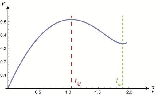
Distance from the projectile to the launch point at any moment for a launch angle of
, which is greater than the critical angle.
This behaviour indicates that in the time interval between tM and tm, the distance between the projectile and the launching point decreases, which means that the object is approaching the launcher. This is a very curious and surprising result since intuitively we would mistakenly think that the projectile always moves away from the launch point, if we looked only at the horizontal direction x of the movement. It is necessary to carry out an exhaustive analysis of the position vector to conclude that there is an interval of launch angles in which, at a certain time interval, the projectile approximates the launcher.
3.1 Evolution of critical points with launch angle
Fig. 2 shows the evolution of critical points resulting from the analysis of the magnitude of position vector,
, that determines the distance from the projectile to the launching point, depending on the launching angle, and always taking into account that we are in higher angles to the critical angle calculated in the previous section, Eq. (17). The inflection point, tip, indicates the time for which variable
changes its curvature. In this particular case, in Fig. 1 we can see that it goes from a concave downwards curvature with a maximum in tM, given by Eq. (12), to an upwards concave curvature with a minimum in tm, given by Eq. (13).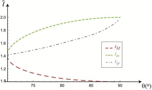
Evolution of the maximum tM, minimum tm and inflection point tip in the function that determines the distance from the projectile to the launching point with the different possible lunching angles, always greater than
.
As can be seen in Fig. 2, as the launch angle θ increases, the maximum tM decreases, asymptotically tending to 1. In other words, for larger launch angles, the point at which the projectile starts approaching the launching point occurs sooner. On the other hand, the minimum time tm increases as θ increases, asymptotically tending to 2. That is, the time at which the projectile starts to move away from the launcher gets longer. From these results, we can state that the time interval in which the object is approaching its original point increases as the launch angle also increases, as can be seen in Fig. 3.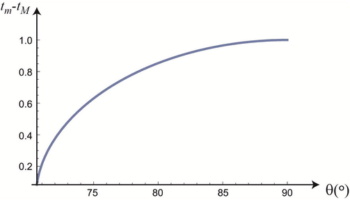
Time interval of the approximation of the projectile to the launching point depending on the launch angle, it being always bigger than.
Note that the time interval of approximation asymptotically tends to 1. Bearing in mind that for (linear motion along the y-axis), the flight time is 2, Eq. (9), it is easy to understand that, for this particular angle, the interval of approximation is half of the time of flight. In a completely vertical launch, for half of the time, the particle is going up and, therefore, moving away from the launcher. And the other half of the time, the particle goes down approximating the launch point.
Regarding the inflection point, it is always closer to the minimum of the function, that is, closer to the value of tm, see Fig. 2. In addition, it has an almost linear shift towards the right in the timeline in the first part of the graph, until the launch angle is just over 80°.
To show all these results in a more visual way, in Fig. 4 we represented the distance from the projectile to the launch point,
, indicating the times at which the maximum, the minimum and the inflection point take place. We also represented the vertical coordinate
and the time at which it reaches its maximum value,
, the point from which the projectile starts to descent vertically. This time corresponds half of the time of flight,
.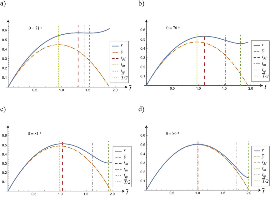
Vertical position of the projectile at each moment,
, the time at which the projectile reaches its maximum height
, the distance from the projectile to the launch point at each moment,
with its corresponding critical points tM, tm and tip for launch angles: a)
; b)
; c)
and d)
As we can see, the time interval in which the projectile is approaching the launch point always takes place when the projectile is descending, and it increases as the verticality of the launch increases. This increase is more pronounced in the angles closer to the critical angle. Note that the maximum time tM, over which the projectile stops moving away from the launcher, is closer to the time in which the projectile reaches its maximum height , until it coincides with the said point for a launch angle of .
3.2 Growth rate of the approximation interval
Analyzing in detail the time interval of approximation to the launch point, in Fig. 5 we have represented the rate,
, at which the interval increases depending on the launch angle
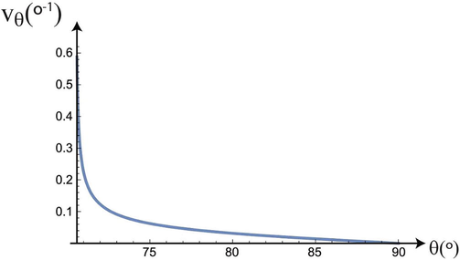
Growth rate of interval tm-tM depending on launch angle.
As we can see, the speed of separation between the critical points tM and tm decreases drastically in the interval close to the critical angle, from 70.6° to 71°. In the last part, for , the decrease of the growth rate of the interval tm-tM is practically linear, with a slope of 0.003.
4 Polar coordinates
Let us analyze the problem in terms of radial and angular coordinates in order to see the situation from another point of view.
In Fig. 6 we have represented any point of the parabolic trajectory corresponding to a parabolic motion in polar coordinates. Note that we are still working with the dimensionless variables defined in the last section, so that the radial coordinate is also non-dimensional. It is evident that this radial coordinate is the magnitude of the position vector, Eq. (10), but expressed as a function of other variables.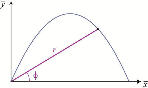
Parabolic trajectory corresponding to the parabolic motion and representation of any point in the trajectory with its polar coordinates.
The dimensionless trajectory equation is given by
Substituting this change of variables, Eqs. (19) and (20), in the trajectory equation, we find
And eliminating the trivial solution
which corresponds to the initial position, we obtain
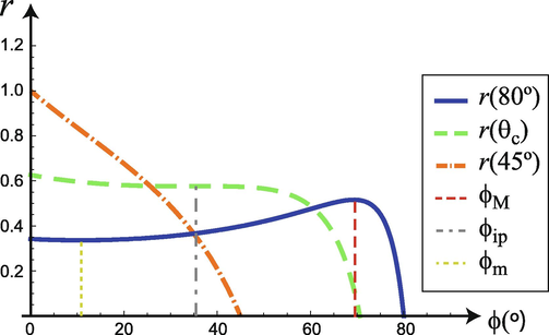
Distance as a function of the angular variable for three initial shot angles. The blue curve (──) corresponds to
, which is above the critical initial angle and, hence it has a maximum,
, and a minimum
, between which the projectile is approaching. The green curve (
 ) corresponds to the critical initial angle,
, which has an inflection point
. And the curve in orange (
) corresponds to the critical initial angle,
, which has an inflection point
. And the curve in orange (
 ) corresponds to an angle
, which is below the critical initial angle and hence the projectile is always moving away from the launcher.
) corresponds to an angle
, which is below the critical initial angle and hence the projectile is always moving away from the launcher.
Using the equality of the tangent of the sum, we obtain
And using Eq. (24),
Which will have real solutions when the discriminant that appears in them is higher or equal to 0, obtaining the same result as in Eq. (17), .
The blue curve in Fig. 7 corresponds to
, which is above the critical initial angle and, hence it has a maximum,
, and a minimum
, between which the projectile is approaching. The curve in orange corresponds to an angle
, which is below the critical initial angle and hence the projectile is always moving away from the launcher. The green curve corresponds to the critical initial angle,
, which has an inflection point
because
Which is the tangent of
, a fact that can be seen using the half-angle tangent formula
5 Conclusions
We have obtained a particularity of projectile motion when launched from the ground and without air friction. The distance between the launched object and the launcher does not always increase. Depending on the launch angle, there is a time interval in which the distance decreases and the object approximates the launcher only to move away once again, if it is possible. This happens when the angle is greater than the critical angle whose value is approximately 70.53°. The critical angle does not depend on speed. Below this angle, this effect does not occur. We can say that this is an effect that only takes place for big angles.
Acknowledgements
AB is grateful to Universidad de Alicante (Spain) for help provided throughout the project GITE-09006-UA. IE is grateful to Ministry of Economy and Competitiveness for the help provided throughout the project RTI2018-099041-B-I00.
Declaration of Competing Interest
The authors declare that they have no known competing financial interests or personal relationships that could have appeared to influence the work reported in this paper.
References
- Maximum ranges in ideal projectile motion – A generalization. Am. J. Phys.. 1990;58(4):408-409.
- [CrossRef] [Google Scholar]
- University Physics with Modern Physics in SI Units (15th ed.). New York: Pearson Education; 2020.
- Principles of Physics (10th ed.). New Jerseys: John Wiley & Sons; 2014.
- Physics for Scientists and Engineers: A Strategic Approach with Modern Physics (4th ed.). London: Pearson Education; 2016.
- Looking at projectile motion from a different angle. Am. J. Phys.. 1978;46(12):1282-1283.
- [CrossRef] [Google Scholar]
- College Physics (11th ed.). Boston: Cengage Learning; 2017.
- Using Statcast to lift the discussion of projectile motion. Am. J. Phys.. 2017;85(4):313-314.
- [CrossRef] [Google Scholar]
- Physics for Scientists and Engineers with Modern Physics (6th ed.). New York: W.H Freeman; 2008.
- Physics for Scientists and Engineers (3rd ed.). Boston: Addison Wesley; 2017.


