Translate this page into:
Modelling of a combustible ionised gas in thermal power plants using MHD conversion system in South Africa
⁎Corresponding author. 211014788@mycput.ac.za (Ayokunle O. Ayeleso), kulama2005@gmail.com (Ayokunle O. Ayeleso),
-
Received: ,
Accepted: ,
This article was originally published by Elsevier and was migrated to Scientific Scholar after the change of Publisher.
Peer review under responsibility of King Saud University.
Abstract
The generation of electric power through the conventional conversion systems may no longer be sufficient to keep pace with the increasing electricity usage and demands. Therefore, an enhancement to these systems can be made by incorporating a topping unit to the existing power plants (thermal, hydroelectric), a direct energy conversion system. Among such is the Magnetohydrodynamics (MHD) system. In an MHD conversion system, electricity is generated when heat energy is converted into electrical energy without the use of mechanical rotating parts. Additionally, the heat energy (ionised gas) required inside the MHD system usually comes from the combustion of fossil fuels. However, this system is still under development in developing countries like South Africa. The current study aims to investigate through simulations and theoretical modelling two existing Open-Cycle Gas Turbines (OCGT) in South Africa (Ankerlig and Gourikwa), which can be converted into Combined-Cycle MHD Gas-Steam Turbines (CCMGST). The processes involved by incorporating the MHD system with these conventional turbines have been further discussed. With setting up a CCMGST in South Africa, the obtained modelling results project an additional generation of electric power which will further improve the existing power generation.
Keywords
Electric power
Thermal plants
Hydroelectric plants
MHD conversion system
Heat energy
Ionised gas
Fossil fuel
CCMGST turbines
OCGT turbines
1 Introduction
In the past years, electric power has been generated using conventional systems such as thermal, hydro and nuclear plants. In these systems, most of the energy obtained during the combustion of fossil fuel is firstly converted into mechanical energy before being converted into electrical energy. The electric power generated from these plants requires huge capital costs and often raises several environmental concerns through the pollution they constantly yield. Additionally, the output efficiency that can be realised from these systems is about 40–45% (Kaushik et al., 1995; Masood et al., 2014; Ayeleso et al., 2015. For the past 50 years, many researchers have been thinking of new energy alternatives and methods that can help to improve the overall efficiency of the conventional power plants. One of such methods is to incorporate to the existing plants a topping unit such as a Magnetohydrodynamic, MHD system, which is a direct energy conversion system (Vishal and Anand, 2013). In the present study, the mode of operation and the theoretical description of an MHD conversion system are presented in Section 2. Section 3 presents the 2-dimensional CFD modelling of a fuel fluid flow through a convergent-divergent nozzle using Ansys Fluent Computational Software. Section 4 provides the theoretical modelling of MHD system and the positive outcome its integration to the Ankerlig and Gourikwa power stations could have in South Africa through means of analytical results.
2 The MHD system
2.1 Mode of operation
The MHD conversion system was initially discovered by Michael Faraday and later extended on a small scale by Ritchie in 1832 (Ritchie, 1932; Aoki et al., 2012; Parsodkar, 2015). In this system, the conductive fluid (natural gas, plasma) is injected from a combustion chamber and flow through an expansion nozzle at high velocity before entering the MHD duct. Inside the MHD duct, the fluid becomes ionised and their velocity is decelerated by a strong magnetic field, B, which creates a retarding force (Lorentz force) that is perpendicular to the direction of the fluid (Parsodkar, 2015). The resulting positive and negative ions of the ionised fluid are then collected by the electrodes placed at 90° to the induced magnetic field, thus producing an electric current (Li et al., 2007; Ayeleso et al., 2015; Mgbachi, 2015).
The configuration of MHD generators varies due to the way the electrodes are connected to the external load. These generators can be categorised as Faraday’s generator (continuous electrodes, segmented electrodes and diagonally connected electrodes), Hall generator and Disc generator (Ayeleso et al., 2015). The detailed procedure and implementation of all these types of Faraday’s generators have been discussed by Ajith and Jinshah (2013).
2.2 Types of fluid cycle in MHD system
An MHD system can be designed either as an open-cycle system or a closed-cycle system.
2.2.1 Open-cycle system
In the open-cycle system, the primary fuel (coal, oil or natural gas) is first processed and burnt in the combustion chamber at high pressure and temperature of about 2300–2700 °C (Masood et al., 2014). To achieve such high temperatures, the compressed air which is usually used to burn the fuel inside the combustor must not be less than 1000 °C. The hot gas is then seeded with the injection of a small amount of ionised potassium carbonate or caesium to increase the gas electrical conductivity. Subsequently, the high pressurised fluid leaving the combustor is expanded through a convergent-divergent nozzle and enters the MHD duct at high velocity of about 1000 m/s, as shown in Fig. 1 (Goel and Shukla, 2015). The hot exhaust gases leaving the MHD duct can be recovered using a heat recovery steam generator to produce more steam that can be used for the bottom unit steam turbine. Subsequently, the seed material is separated from sulphur, S and nitrogen, N2 and then recycled back into the combustor (Kayukawa, 2004; Islam et al., 2013; Salvatore and Alessandra, 2014; Masood et al., 2014; Goel and Shukla, 2015; Sharma and Gambhir, 2015). The achievable power capacity of this system is about 100 MW and an efficiency of about 60% can be realised with better heat recovery systems (Vishal and Anand, 2013).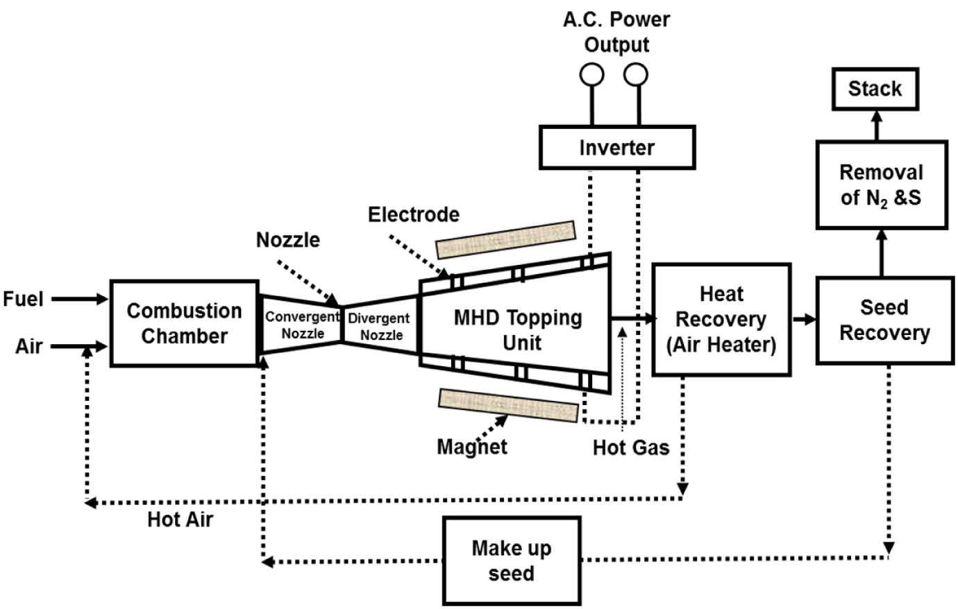
Open-cycle MHD system (Sharma and Gambhir, 2015).
An open-cycle Faraday type MHD generator such as the pulsed MHD generator “Sakhalin” was developed in the former Soviet Union. This generator consists of an MHD channel of 4.5 m long and is equipped with continuous electrodes (inlet area, 0.9 m × 1 m and outlet area, 1.6 m × 1 m). In addition, the working fluid used in the Sakhalin generator is solid propellant with a mass flow rate of about 800 kg/s. The maximum electric power output obtained from this generator is about 510 MW (Ishikwa et al., 2007), (Vishal and Anand, 2013). Other components of the Sakhalin generator are a plasma generator (combustor) with temperature of about 3800 K, an air-core magnet system consisting of two racetrack coils, a magnetic flux density of up to 2.5 T and a combustor pressure of about 4.0–5.6 MPa. In 1975, an open-cycle MHD generator was further developed by the USSR with a capacity of 25 MW and a mass flow rate of about 50 kg/s (Vishal and Anand, 2013). Subsequently, in 1979, a joint USSR effort generator was developed with a medium capacity of 10 MW and a mass flow rate of about 50 kg/s (Vishal and Anand, 2013). In another study, Avco-Everett Research Laboratory, Massachusetts successfully demonstrated a test on segmented MHD generator in 1959. The working fluid used inside this generator was arc heated argon seeded with powdered potassium carbonate with a velocity of about 240 m/s (Mach 0.7) and an operating temperature of about 2800 K. An output power of 11 kW was obtained from this generator (Kantrowitz et al., 1962; Sutton and Sherman, 1965; McClaine et al., 1989).
There have also been some computational investigations involving the optimisation of combustion chamber geometry, injection timing and duration of the ionised fluid flowing into the MHD duct. In 2015, a study led by Martinas and co-workers has modelled the finite volume and the combustion inside a direct injection natural gas engine using non-premixed combustion (Martinas et al., 2015). Another study was thereafter conducted to improve significantly the quantity of power that can be generated in coal fired plants using MHD system (Poonthamil et al., 2016).
2.2.2 Closed-cycle system
In the closed-cycle system, the inert gas is heated by a high temperature heat exchanger 1 (about 2000 °C) and seeded with caesium vapour to get ionised. The ionised gas then flows through the MHD duct to produce DC power. The exhaust hot gas from the MHD duct is recovered and recycled to produce more steam through the heat exchanger 2, as shown in Fig. 2. The combustion products are sent to the stack after removal of heat in the heat exchanger 1 (Ajith and Jinshah, 2013; Goel and Shukla, 2015). The closed-cycle MHD generator is not commonly used unlike the open-cycle MHD generator. However, the achievable power capacity of this system is about 200 MW and an efficiency of about 60% can be realised (Kayukawa, 2004; Vishal and Anand, 2013; Ajith and Jinshah, 2013; Islam et al., 2013; Goel and Shukla, 2015; Sharma and Gambhir, 2015).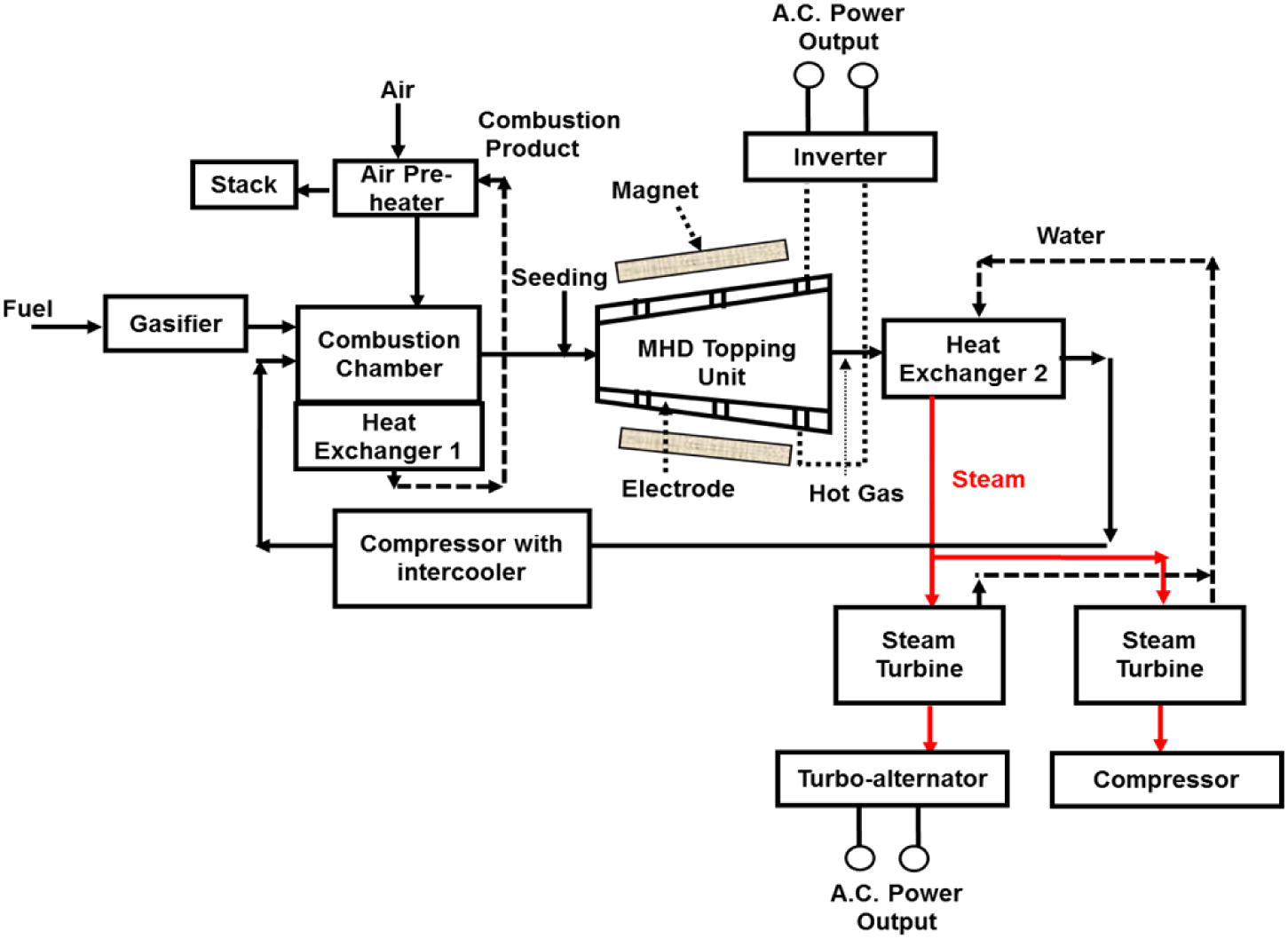
Closed-cycle MHD system (Goel and Shukla, 2015).
2.3 Possibility of MHD generation in South Africa
The two gas turbine power stations selected for this study are the South African Ankerlig and Gourikwa Open-Cycle Gas Turbines (OCGT). In the Ankerlig power station, there are nine electricity generating units grouped into two phases, comprising of 4 and 5 units, with each unit consisting of a gas turbine, GT, (148.2 or 149.2 MW). The combined nominal capacity of all the nine units is about 1338 MW (Phase-1: 149.2 MW × 4 units + Phase-2: 148.2 MW × 5 units) (Eskom, 2014; Pollet et al., 2015). While in the Gourikwa power station, there are five electricity generating units, with each unit also consisting of a gas turbine. The combined nominal capacity of all the five units is about 746 MW (149.2 MW × 5 units) (Spalding-Fecher, 2011; Pollet et al., 2015). Primary fuel like coals, natural gas (propane) and petroleum derivative (kerosene or diesel) are presently used in these stations (Eskom, 2014; Silinga and Gauché, 2014). The operation of the Ankerlig and the Gourikwa OCGT begins when the atmospheric air is compressed and mixed with the fuel inside the combustion chamber (1030–1200 °C). The resulting fuel–air mixture is then burnt to produce a high velocity gas which is used to turns the turbine shaft connected to the rotor of the generator. As the rotor turns inside the stator, electricity is generated and distributed through a high voltage transmission system (Fig. 3). An efficiency of about 35% can be realised from OCGT stations (Eskom, 2014). The Ankerlig and Gourikwa OCGT can be converted into a more efficient Combined-Cycle Gas-Steam Turbines (CCGST), as shown in Fig. 3.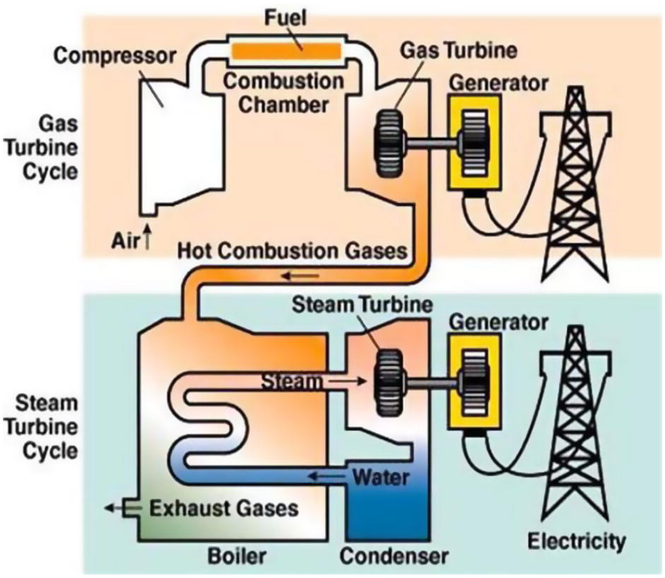
Example of a conventional system using a Combined-cycle gas-steam turbine system (Energy without Carbon, 2015).
The combination of a Brayton cycle (gas turbine) to a Rankine cycle (steam turbine) is often referred to as a combined-cycle. The idea of converting the OCGT to a CCGST is to utilise the hot exhaust gases (about 600 °C) energy exiting from the gas turbine to create steam (water vapour) in a heat recovery steam generator (HRSG) to drives the bottom unit as a steam turbine. The mechanical energy produced from the steam turbine is then converted to electrical energy using the generator. Subsequently, a condenser is used to convert the exhaust steam from the steam turbine back into the HRSG through a cooling process. The steam turbine gives another 30% efficiency making the overall generating efficiency of the CCGST to be about 65% (Eskom, 2014; Energy without Carbon, 2015). Taking Gourikwa power station as a case study, it was estimated that each converted CCGST unit will generate an additional 80 MW capacity, with a total nominal capacity of approximately 1146 MW (80 MW × 5 units + 746 MW) (Eskom, 2014). While in the Ankerlig power station, each converted CCGST unit will also generates an additional 80 MW capacity, with a total nominal capacity of approximately 2058 MW (80 MW × 9 units + 1338 MW).
In addition, with the increasing electricity usage and demands in South Africa, these total nominal capacities can be substantially improved by combining to each unit of the CCGST, an MHD system. Therefore, from now, the focus will be centred on the possibility to couple an MHD topping unit to the Ankerlig and Gourikwa CCGST. The advantage of this system is that the exhaust heat rejected by the MHD topping unit can be re-used by the CCGST, as shown in Fig. 4.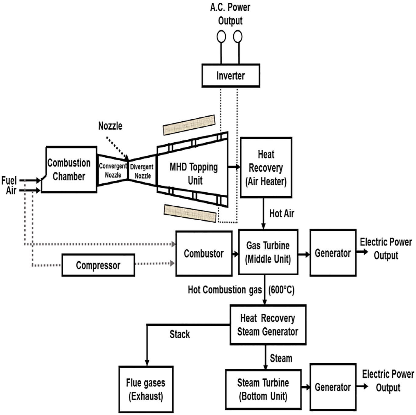
Combined-cycle MHD gas-steam turbine (CCMGST) system.
2.4 MHD system description
2.4.1 Analysis of MHD generator
The conductive fluid flowing inside an MHD generator moves with high velocity,
, through a magnetic field which slow down their motion. As the fluid cut through the magnetic force lines, an electrical energy is then generated. The force, F, and the electric field, E, acting on the fluid particles is given by Ajith and Jinshah (2013) and Islam et al. (2013),
The open circuit voltage, V, inside the MHD generator can be determined from the fluid velocity, magnetic field, B, and the distance, l, between the electrodes, as given by Ajith and Jinshah (2013) and Poonthamil et al. (2016),
The maximum flowing current inside the MHD generator is given by Ajith and Jinshah (2013) and Poonthamil et al. (2016),
The maximum voltage inside the MHD generator is given by Ajith and Jinshah (2013) and Poonthamil et al. (2016),
The output power, P, that can be extracted from the MHD generator is given by Ajith and Jinshah (2013),
In an open circuit MHD system, the maximum power, Pmax, that can be extracted from the generator electrodes is given by Ajith and Jinshah (2013) and Sivaram et al. (2015),
2.4.2 MHD equations
The MHD equations for fluid flow include the Navier–Stokes momentum equation, mass continuity equation Maxwell’s equation and ohm’s Law.
The differential form of Navier–Stokes momentum equation can be written as (Aoki et al., 2012; Ajith and Jinshah, 2013),
The mass continuity equation can be written as,
The Maxwell’s equation can be written as,
The Ohm’s laws equation can be written as,
3 Two-dimensional modelling of a fuel fluid flow through a convergent-divergent nozzle
The commonly used fuel in Ankerlig and Gourikwa thermal plants is diesel. Thus, this fuel has been selected for the present fluid flow modelling. In this model, the diesel exhaust flowing from the plants combustion chamber passes through a convergent and divergent nozzle before entering the MHD system (Fig. 5). The purpose of the nozzle is to accelerate the fluid velocity up to the required Mach number.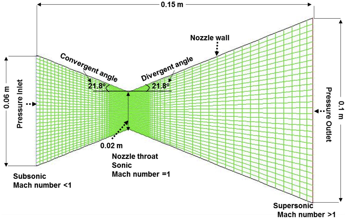
Nozzle geometry.
The supersonic propelling nozzle (Fig. 5) uses heat energy of the fuel exhaust to accelerate the fluid (gas) to a very high speed (Surya Narayana and Sadhashiva Reddy, 2016). The nozzle geometry and the compressible flow analysis were performed using Ansys Fluent 16.2 Software. The boundary conditions are also set in such a way that when the fluid pressure increases at the nozzle inlet, their velocity must be very low (Subsonic). As the fluid passes through the nozzle throat, the pressure begins to decrease (Sonic) and the velocity distribution increases towards the nozzle outlet (Supersonic).
For the simulation parameters, a quadrilateral dominant shaped mesh is used for all the calculation. The mesh sizes were carefully chosen to attain sufficient accuracy within a reasonable computational time and no critical errors were discovered. The complete mesh results consist of 2790 elements and 2912 nodes. The nozzle problem setup and boundary conditions are listed in Table 1 (Velikhov et al., 1999; Hardianto et al., 2008; Tu et al., 2008; Deshpande et al., 2014; ANSYS Inc, 2015; Butt and Arshad, 2015).
General setup
Solver type: density-based,
2D space: planar,
Time: steady
Velocity formulation: absolute
Models
Energy equation: On
Viscous model: Standard k-epsilon model, Standard wall function
Materials
Fluid: diesel-air species,
Density: ideal-gas,
viscosity = 1.72e-05 kg/m-s,
Thermal conductivity = 0.0454 W/m-K,
Mass diffusivity = 2.88e-05 m2/s
Cell zone boundary condition
Fluid domain
Boundary conditions
Inlet: pressure-inlet,
Gauge Total Pressure = 3e5 Pa = 3 bar,
Outlet: pressure-outlet,
Gauge Total Pressure = 0 Pa,
Inlet Temperature = 2000 K,
Outlet Temperature = 300 K (for initialisation purpose only)
3.1 Convergent-divergent nozzle simulation results
From the contour of velocity distribution (Fig. 6), the diesel-air exhaust is minimum at the inlet (68 m/s) and continue to increase along the nozzle throat up till the nozzle outlet (1088 m/s). The velocity magnitude is Mach 1 at the nozzle throat section. This state is also known as the choked flow condition. The Mach number at the nozzle outlet is approximately 2.35 (Fig. 6).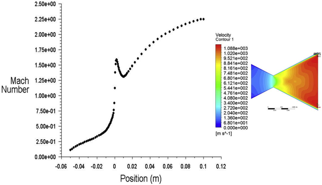
Plot of Mach number and velocity along the nozzle wall position.
From the contour of temperature distribution (Fig. 7), the temperature of the gas fluid is maximum at the inlet and continue to decrease along the nozzle throat up till the nozzle outlet. The magnitude of temperature at the outlet is 1782 K (Fig. 7).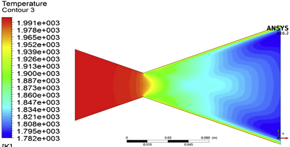
Contour of nozzle temperature.
From the contour of pressure distribution (Fig. 8), the gas fluid pressure is maximum at the inlet and continue to decrease along the nozzle throat up till the nozzle outlet. The sudden reduction of pressure after the nozzle throat is due to shock wave just after the throat section (Fig. 8).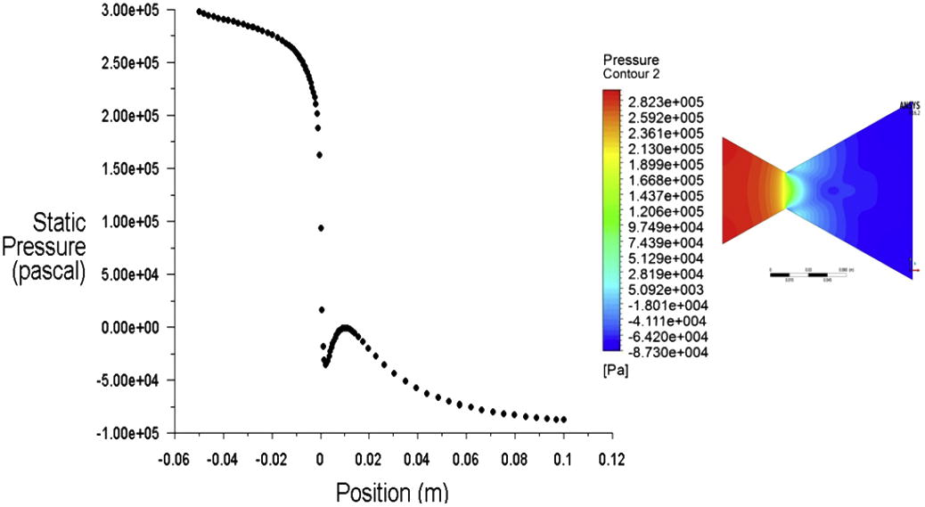
Plot and contour of pressure along the nozzle wall position.
4 Theoretical modelling of an MHD system coupled to Ankerlig and Gourikwa CCGST
The high-speed (supersonic velocity) exhaust gas fluid (Fig. 6) exiting the nozzle outlet, can be used as an input data for the modelling of MHD topping unit in Fig. 4. The MHD system can be modelled theoretically using the parameters described in Table 2 (Sawhney and Verma, 1988, 1995; Velikhov et al., 1999; Ishikwa et al., 2007; Hardianto et al., 2008).
Parameters
Model 1
Model 2
Simulated diesel exhaust velocity (v)
1088 m/s
1088 m/s
Magnetic field (B)
2 T
2.5 T
Diesel exhaust conductivity (σ)
15 mho/m
20 mho/m
Electrode surface area (A)
1 m2
1.6 m2
Distance between the electrode (l)
1 m
1.6 m
4.1 Theoretical results
The maximum voltage and power that can be obtained from the MHD topping unit are given by Eqs. (4) and (6) Ajith and Jinshah (2013) and Poonthamil et al. (2016),
Model 1:
Model 2:
For the Ankerlig and Gourikwa CCGST stations, the MHD system will produce a total power capacity of 160 MW (17.76 MW × 9 units) and 89 MW (17.76 MW × 5 units), respectively (Model 1). Similarly, a total capacity of 852.3 MW (94.7 MW × 9 units) and 473.5 MW (94.7 MW × 5 units) will be produced in the second model for both stations (Table 3). The conversion efficiency of the MHD topping unit in each model can be determined as follows (Ajith and Jinshah, 2013; Poonthamil et al., 2016):
Model 1 & 2 OCGT: a149.2 MW (Ankerlig Phase-1 gas turbine unit) × 4, b148.2 MW (Ankerlig Phase-2 gas turbine unit) × 5, c149.2 MW (Gourikwa gas turbine unit) × 5. Model 1 & 2 OCGT to CCGST increments: d80 MW (1 unit of increment) × 4, e80 MW (1 unit of increment) × 5, f80 MW (1 unit of increment) × 5. Model 1 MHD: g17.76 MW (Ankerlig Phase-1 MHD unit) × 4; h17.76 MW (Ankerlig Phase-2 MHD unit) × 5; i17.76 MW (Gourikwa MHD unit) × 5. Model 2 MHD: j94.7 MW (Ankerlig Phase-1 MHD unit) × 4; k94.7 MW (Ankerlig Phase-2 MHD unit) × 5; l94.7 MW (Gourikwa MHD unit) × 5.
Model 1 parameters
GT units
OCGT (MW)
OCGT to CCGST increments (MW)
CCGST (OCGT+ Increment), (MW)
MHD (MW)
CCMGST total capacity (MW)
Ankerlig Station
Phase-1
4
597 a
320 d
917
71 g
988
Phase-2
5
741 b
400 e
1141
89 h
1230
Gross Output Power [Phase 1 & 2]
9
1338
720
2058
160
≈2218
Gourikwa Station
Gross Output Power
5
746 c
400 f
1146
89 i
≈1235
Model 2 Parameters
GT Units
OCGT (MW)
OCGT to CCGST Increments (MW)
CCGST (OCGT + Increment), (MW)
MHD (MW)
CCMGST Total capacity (MW)
Ankerlig Station
Phase-1
4
597 a
320 d
917
378.8 j
1295.8
Phase-2
5
741b
400 e
1141
473.5 k
1614.5
Gross Output Power [Phase 1 & 2]
9
1338
720
2058
852.3
≈2910
Gourikwa Station
Gross Output Power
5
746 c
400 f
1146
473.5 l
≈1620
From the conversion of OCGT to CCGST, the power capacity of Ankerlig station was increased from 1338 MW (Phase-1: 149.2 MW × 4 units + Phase-2: 148.2 MW × 5 units) to 2058 MW (80 MW × 9 units + 1338 MW), while in the Gourikwa station, the power capacity was increased from 746 MW (149.2 MW × 5 units) to 1146 MW (80 MW × 5 units + 746 MW), as shown in Table 3. This gives an overall generating cycle efficiency of about 65%. The coupling of model 1 MHD unit to each of the 9 electricity generating units in the Ankerlig CCGST station projects a total nominal capacity of approximately 2218 MW for the CCMGST plant, as shown in Table 3. Similarly, the coupling of model 1 MHD unit to each of the 5 electricity generating units in the Gourikwa CCGST station projects a total nominal capacity of approximately 1235 MW for the CCMGST plant.
Furthermore, the coupling of model 2 MHD unit to each of the 9 generating units in the Ankerlig CCGST station projects a total nominal capacity of approximately 2910 MW for the CCMGST plant (Table 3). Similarly, the coupling of model 2 MHD unit to each of the 5 generating units in the Gourikwa CCGST station projects a total nominal capacity of approximately 1620 MW for the CCMGST plant. Hence, the overall generating efficiency of these power plants has increased. To achieve these gross output capacities, the ionised hot gas at the MHD exhaust is passed into an air heater, where the gas is recovered and re-used in the gas turbine unit (Fig.4). Similarly, the gas turbine exhaust is also recovered by a steam recovery system with supplementary firing.
5 Conclusions
This study has investigated the possibility of coupling an MHD system to South African power stations, namely Ankerlig and Gourikwa. Based on the proposed theoretical models, a significant observation was that an increment in fluid electrical conductivity, magnetic field, electrode surface area and the distance between the electrode may positively influenced the total capacity of the MHD coupling. From this investigation, the additional power capacity obtained when incorporating the MHD generator with these power plants can be used to improve electricity generation in South Africa. Aside of using the MHD generator for commercial and industrial purposes only, it could also be used to increase the speed and efficiency of railway engines. Additionally, the MHD can be of great benefit in many other fields such as plasma physics, bio-engineering and aerodynamics.
Acknowledgements
The Authors would like to thank the Department of Electrical, Electronics & Computer Engineering, Cape Peninsula University of Technology (CPUT), South Africa for providing financial support and the software used for the realization of this work.
References
- ANSYS Inc, 2015. ANSYS FLUENT 16.2. Theory Guide, USA.
- A Magnetohydrodynamics study of behavior in an electrolyte fluid using numerical and experimental solutions. Therm. Eng (Engenharia Termica). 2012;11(1–2):53-60.
- [Google Scholar]
- Ayeleso, A.O., Kahn, M.T.E., Raji, A.K., 2015. Plasma energy conversion system for electric power generation. In: 12th International Conference on the Industrial and Commercial Use of Energy, Cape Town, South Africa, pp. 1–6.
- Design and analysis of a clustered nozzle configuration and comparison of its thrust. Student Res. Paper Conf.. 2015;2(19):105-109.
- [Google Scholar]
- Eskom, 2014. Fact sheet Ankerlig and Gourikwa Gas Turbine Power Stations.
- Three-dimensional flow analysis in a faraday-type MHD generator. IEEE Trans. Ind. Appl.. 2008;44(4):1116-1123.
- [Google Scholar]
- Three dimensional computational of Magnetohydrodynamics in a weekly ionized plasma with strong MHD interaction. J. Mater. Process. Technol.. 2007;181:254-259.
- [Google Scholar]
- The Magnetohydrodynamics power generator-basic principles, state of the art, and areas of application. IRE Trans. Mil. Electron.. 1962;6(1):78-83.
- [Google Scholar]
- Solar-assisted liquid metal mhd power generation: a state of the art study. Heat. Recov. Syst. Chp.. 1995;15(7):675-689.
- [Google Scholar]
- Open-cycle Magnetohydrodynamics electrical power generation: a review and future perspectives. Prog. Energ. Combust. Sci.. 2004;30:33-60.
- [Google Scholar]
- Li, P., Barry, G., Castellanos, S., Chan, C., Do, K., Gamez, C., Kuhn, J.A., 2007. Leon, Power Generation Using Magnetohydrodynamic Generator with a Circulation Flow Driven by Solar-Heat-Induced Natural Convection. <http://cfpub.epa.gov/ncer_abstracts/index.cfm/fuseaction/display.highlight/abstract/8630/report/F>.
- Martinas, G., Cupsa, O.S., Buzbuchi, N., Arsenie, A., 2015. Modelling with finite volume the combustion in direct injection natural gas engine using non-premixed combustion model. In: 5th International Conference on Innovative Computing Technology (INTECH), Galicia, Spain, May 20–22, pp. 72–77.
- Integration of magnetohydrodynamics (MHD) power generating technology with thermal power plants for efficiency improvement. World. Appl. Sci. J.. 2014;32(7):1356-1363.
- [Google Scholar]
- McClaine, A., Pinsley, J., Pote, B., 1989. Experimental investigation on the effects of the TRW two stage coal combustor on the performance of the AVCO Mk VI MHD generator. In: Proceedings of the 24th Intersociety Energy Conversion Engineering Conference. Washington, DC, USA, 6–11 Aug.
- Design analysis of Magnetohydrodynamic (MHD) electrical power generation technology. IJOART. 2015;4(10):103-108.
- [Google Scholar]
- Current energy landscape in the Republic of South Africa. IJHE. 2015;40:16685-16701.
- [Google Scholar]
- Enhancement of power generation in thermal power plant using MHD System. IOSR-JMCE. 2016;1(5):142-146.
- [Google Scholar]
- Experimental researches in a voltaic electricity and electromagnetism. Philos. Trans. R. Soc. Lond.. 1932;122:279-298.
- [Google Scholar]
- Performance analysis of integrated systems Based on MHD Generators. 68th Conference of the Italian Thermal Machines Engineering Association, ATI2013. Energy Procedia. 2014;45:1305-1314.
- [Google Scholar]
- Optimum liquid fuel mixture for MHD power generators. Energ. Convers. Manage.. 1988;28(2):137-141.
- [Google Scholar]
- Optimum power generation characteristics of an MHD generator with kerosene oil-heavy fuel oil mixture as working fluid. Energ. Convers. Manage.. 1995;36(5):343-353.
- [Google Scholar]
- Scenarios for a South African CSP peaking system in the short term. Energy Procedia. 2014;49:1543-1552.
- [Google Scholar]
- Performance investigation of a closed cycle magneto hydrodynamics power plant with liquid metal as heat source. INDJST. 2015;8(21):1-6.
- [Google Scholar]
- What is the carbon emission factor for the South African electricity grid? Poor management is consulting. JESA. 2011;22(4):8-12.
- [Google Scholar]
- Simulation of convergent divergent rocket nozzle using CFD analysis. IOSR-JMCE. 2016;13(4):58-65.
- [Google Scholar]
- Engineering Magnetohydrodynamics. New York: McGraw-Hill; 1965.
- Computational Fluid Dynamics: A Practical Approach (first ed.). Butterworth-Heinemman; 2008.
- Velikhov, E.P., et al., 1999. Pulsed MHD power system SAKHALIN-the World largest solid propellant fueled MHD generator of 500 MWe electric power output. In: Proceedings of 13th International Conference on MHD Power Generation and High Temperature. 12, pp. 387–398.
- The future power generation with MHD generators magneto hydrodynamics generation. Int. J. Adv. Electr. Electron. Eng.. 2013;2(6):2278-8948.
- [Google Scholar]
Appendix A
Supplementary data
Supplementary data associated with this article can be found, in the online version, at http://dx.doi.org/10.1016/j.jksus.2017.01.007.
Appendix A
Supplementary data


