

Ferroelectric sensor BaxSr1-xTiO3 integrated with android smartphone for controlling and monitoring smart street lighting
⁎Corresponding author. irzaman@apps.ipb.ac.id (Irzaman)
-
Received: ,
Accepted: ,
This article was originally published by Elsevier and was migrated to Scientific Scholar after the change of Publisher.
Peer review under responsibility of King Saud University.
Abstract
In this report, we demonstrated an application of a thin film Barium Strontium Titanate (BST) as a light sensor integrated with an Android smartphone as a model of smart street lighting. BST thin films were fabricated using chemical solution deposition methods followed by spin coating with a variety of mole fractions. We assumed that changes in the lattice parameters of its tetragonal crystal structure caused by variations in the mole fraction result in different ions displacement characteristics that induce charges polarization in the crystal structure. We have confirmed that the BST thin film with mole fraction x = 0.500 was the best thin film for the light sensor in this prototype. Furthermore, it has been found that the smart street lighting gives ∼69.23 % power saving and lower power usage than a conventional street lighting. Additionally, this developed system has successfully reported the lamp status that is to be maintained to an Android phone of the maintainer by using a short message system. This self-reporting makes it easy for maintainer to identify broken lamps and to do repairs. Moreover, implementation of such features to the street lighting can reduce the operating cost.
Keywords
BST thin film
Controlling and monitoring
Integrated android smartphone
Internet of things
Light sensor

1 Introduction
A light sensor research field has been attracted researchers because it is an important part that has to install on the lighting control system to optimize energy usage for lighting (Bachanek et al., 2021; Chiang, 2014; Kurniawan et al., 2020; Matta & Mahmud, 2010; Warmerdam et al., 2016). Energy consumption for lighting is around 15–19 % of the world's total energy demand (Bachanek et al., 2021); in contrast, almost 90 % of building parts do not require too much light.
The thin-film ferroelectric BaxSr1-xTiO3 (BST) has been widely reported as the light sensor and is relatively stable in the atmosphere environment (Batalov et al., 2020; Pavlov et al., 2021; Satheeskanth et al., 2022)., The performance stability of sensors applied in an open environment is essential to ensure that the detection function is guaranteed, such as the light sensor in a street lamp. It has been reported that the BST thin film was utilized as a passivation layer for chemical sensors because it has excellent stability against environmental conditions (Huck et al., 2014a, Huck et al., 2014b). Besides, it is facile to adjust the curie temperature by varying Sr atom to obtain a high dielectric constant and low leaked current (Kuzmina et al., 2009; Lee & Rhee, 1999). Addition, BST has a perovskite structure where Ba/Sr (2 + ) ions are in the eight corners of the tetragonal, Ti (4 + ) ions are at the diagonal point of space, then O (2-) ions are at six plane diagonal points. Therefore, controlling the shift of Ti (4 + ) to the z-axis direction depends on Ba/Sr (2 + ) contain that can adjust the dipole moment and polarization value. Moreover, the BST thin films are facile to prepare under atmosphere environment and solution-processable (Chunli Diao et al., 2016; Irzaman et al., 2011; Kim & Gaponenko, 2009; Misbakhusshudur et al., 2016; Panomsuwan & Manuspiya, 2020; Teh et al., 2017; Tyunina et al., 2008).
Our group has reported that several ferroelectric materials such as BaxSr1-xTiO3, LiTaO3, LiNbO3, PbxZr1-xTiO3 are able to implement as the light sensor, a thermal sensor, an infrared sensor, and a photovoltaic (Irzaman et al., 2003, 2016,2018,2019; Misbakhusshudur et al., 2016; Syafutra et al., 2013). Interestingly, all ferroelectric thin films were fabricated using a chemical solution deposition (CSD) method followed by spin coating. This method is known as simple and low cost in preparing thin films. A perovskite structure of the ferroelectric material provides a spontaneous polarization to a central atom in the perovskite structure when it interacts with an external electric field, so that gives a promise for the light sensor (Chunarrom & Manuspiya, 2021; Liu et al., 2020).
Several methods have been reported for preparing BST thin films; metal–organic chemical vapor deposition, chemical vapor deposition, sol–gel, atomic layer deposition, pulsed laser ablation deposition, RF sputtering, hydrothermal and CSD (Diao et al., 2016; Gao et al., 2000; Irzaman et al., 2011; Kim & Gaponenko, 2009; Li et al., 2016; LIU et al., 2006; Teh et al., 2017; Yogaraksa et al., 2004; Zhu et al., 2005). However, preparing BST thin films using CSD follow spin coating provides advantages; easy to control stoichiometry, processed under ambient temperature and atmosphere, and low cost. Controlling the stoichiometry to vary the mole fraction of BST thin film give the advantage to shift the Currie temperature (Henaish et al., 2021; Lv et al., 2020). Another advantage of controlling the mole fraction is controlling the dielectric constant and dielectric loss, a case study in nanoceramics of Ba1-xCaxZrO3 (Satheeskanth et al., 2022).
Street lighting is one of the most important facilities of a city to provide safer for road users. Therefore, almost 40 % of a city's budget is allocated to support the street lighting system (Cacciatore et al., 2017). One of the attempts to reduce operating costs is integrating the street lights with solar cells systems. However, if the battery is not fully charged during the day, the lights will not operate optimally at night. Usually, the street lights are not equipped with automatic control to save electrical energy sources, so they tend to use maximum electrical energy. In addition, directly checking is needed to ensure the street lights are operating normally. These kinds of problems will undoubtedly increase operating costs. Therefore, the smart street lighting system is one solution to reduce operational costs, reduce the use of electrical energy, and reduce carbon emissions. In this system, besides being able to turn on and off the lights automatically, it can also adjust the intensity of the lights based on time, and send the report regarding broken lamps to the maintainer.
2 Methods
2.1 Devices fabrication
Precursor solutions of BST were prepared by dissolving barium acetate/Ba(CH3COO)2, strontium acetate/Sr(CH3COO)2, and titanium isopropoxide/Ti(OCH(CH3)2)4 into a solvent of 2-Methoxyethanol/C3H8O2 with concentration one molar. To obtain precursor solutions with mole fraction (x = 0.125; 0.250; 0.375; 0.500; 0.625; 0.750; 0.875; 1.000), weights of reactants were determined following a chemical reaction below:
xBa(CH3COO)2 + (1-x) Sr(CH3COO)2 + Ti (OCH(CH3)2)4 + y O2 → BaxSr1-xTiO3 + z H2O + v CO2.
The precursor solution of BaxSr1-xTiO3 with particular mole fraction was deposited on clean substrates of p-type Si (1 0 0) (Irzaman et al., 2016; Syafutra et al., 2013). The deposition technique was spin coating with parameters 3000 rpm for 30 s, and there were three repetitions with a delay of 60 s for each repetition. Formed films, then annealed at 850 °C for 15 h in a furnace of VulcanTM-3-130. The temperature increment inside the furnace was kept constant at 1.67 °C/minute till reaching the temperature of 850 °C, while a cooling process followed a normal cooling. Metal contact (Al) as electrodes were deposited on both surfaces of the silicon substrate and the BST thin film using the thermal vaporization technique resulting in a thickness of 100 nm and an area of 2 × 2 mm2 (Irzaman et al., 2003). After the copper wires were attached to electrodes and placed inside a transparent container, it was called a sensor device. Fig. 1 show an illustration of this sensor device.
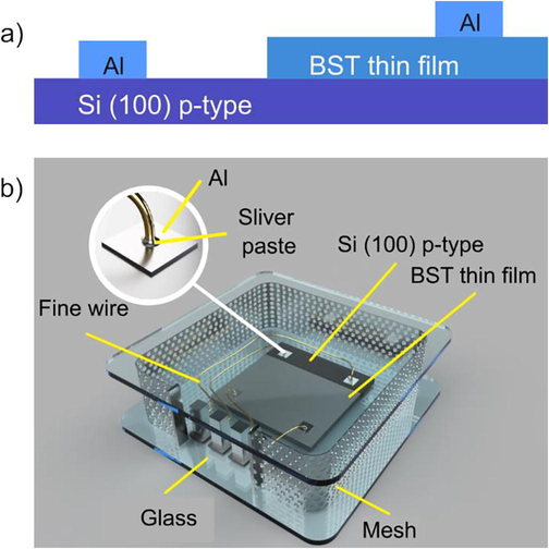
- Schematic illustration of (a) cross section of the BST thin film and (b) the BST thin film in the transparent storage.
2.2 Devices characterization
A Wheatstone bridge (Fig. 2) is an electronic circuit to characterize the sensitivity and hysteresis characteristics of the sensor device (Castro et al., 2018; Quynh et al., 2016). The term of sensitivity (S) of the sensor device in this characterization was defined as a ratio of a change in a voltage (ΔV) to the change in light intensity (ΔI), which falls on the sensor (S = ΔV/ΔI). The change in light intensity in the sensitivity examination was a difference between dark (±2 lm/m2) and bright (±470 lm/m2) conditions. In addition, the voltage bias condition to the sensor device during sensitivity examination was conducted in two conditions: forward bias and reverse bias conditions (Mohammadmoradi et al., 2018). Meanwhile, for examination of hysteresis characteristics was conducted by exposing the sensor device with varying light intensities (Benhouria et al., 2016). The changes in output voltage for each cycle of increasing and decreasing light intensity will be recorded. The hysteresis index then calculated with a following equation: [output voltage with increasing in light intensity - output voltage with decreasing in light intensity]/output voltage with increasing in light intensity × 100 %.
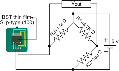
- Schematic illustration of BST thin film is loaded to the Wheatstone Bridge circuit to amplify a small change in the BST thin film resistance as the result of the light exposure. The BST thin film in this figure is biased as forward bias. While in reverse bias, the Al contact on the Si p-type is connected with the resistor 100 Ω; meanwhile, the Al contact on the BST thin film is connected with the resistor 1 MΩ.
2.3 Design of smart street lighting systems
A prototype of the smart street lighting system consisted of four basic modules: thin-films BST as a light sensor, Global System for Mobile Communications (GSM) as a communication protocol, smartphone, and automation module (Irzaman et al., 2018). In general, the prototype has features; 1) automatically adjusting the intensity of street lamps following the time-status-based dimming, 2) remotely controlling street lamps to turn on and off via the Android smartphone, and 3) automatically detecting street lamps that must be repaired, then automatically sending a report to the smartphone of the maintainer. The report will send through the GSM protocol to prevent any possibility of interference with the internet network (Felix & Jacob Raglend, 2011; Rahman et al., 2015). Please see Fig. 3 for a schematic illustration.
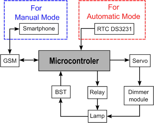
- Blok diagram of smart street lighting system for automatic and manual controlling.
2.4 Design of electronic circuits and Android App for controlling via smartphone
The electronic circuit is built from input and output modules processed using the NodeMcu V3 microprocessor module. The input module consists of a real-time clock (RTC), GSM, and light sensor using BST. While the output module consists of: module of a relay, a servo motor, pulse width modulation 2000 automatic current (PWM 2000 AC), and 16x2 liquid crystal display (LCD). The function of the RCT module is to provide timing input to the NodeMcu V3 microprocessor to adjust the intensity of the street light based on the set time. The GSM module functions to send messages to the Android smartphone of the maintainer regarding the status of the street light after it is detected as damaged by the BST sensor. The relay module functions as a switch to open and close the current flow for turning on/off street lights. The servo motor module will be utilized to turn the PWM 2000 AC module knob to adjust the street light's intensity (Bodur et al., n.d.; Porkia et al., 2022). Finally, the 16x2 LCD module functions to display the IP address of the street light on each pole. Schematic illustration of electronic circuits can be shown in Fig. 4.
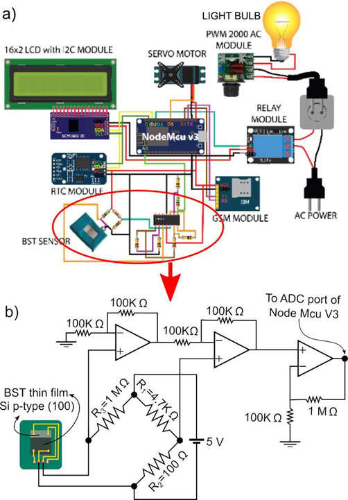
- Illustration of (a) connection of electronic modules in the smart street lighting, and (b) amplifier circuit based on Op-Amp to amplified the signal from the BST thin film. We call Op-Amp devices from left to the right Op-Amp1, Op-Amp2, and Op-Amp3.
We utilized the Operational Amplifier (Op-Amp) circuit as signal processing before sending it to the NodeMcu V3 microprocessor, shown in Fig. 4(b). The voltage across the BST thin film was amplified two times by Op-Amp1, then the result will become an input of Op-Amp2 in its inverting input. In Op-Amp2, the voltage across the R2 (100 Ω) (non-inverting input) was amplified two times before subtracted by its inverting input. Then, the output voltage of Op-Amp2 was amplified eleven-time by Op-Amp3. The output voltage from Op-Amp3 will be sent to the analog to digital converter (ADC) port of NodeMcu V3 that has the 10-bit resolution (Khwanrit et al., 2018; Satheeskanth et al., 2022). These Op-Amp circuits will result in output voltages of Op-Amp3 being 1.738 V if the BST sensor receives the light and 0.088 V if there is no light from the streetlamp. The microcontroller will identify whether the streetlamp is damaged or not, based on both voltage values. If the microcontroller senses the voltage of 0.088 V, where it should be 1.738 V (condition when the streetlamps should be in turn on).
The Android App. for the smartphone was made using “MIT App Inventor,” which provides complete features for developing Android-based applications. In this case, the Android App for this system has settings menus that function to monitor and control smart street lights, as shown in Fig. 5. The App has three button and one slider-button witch that have particular functions. The four buttons, each of which functions to turn off, turn on, adjust the intensity of the light, and selecting the street lamps. These three buttons will only be active if the slider-button switch is in the ON position.
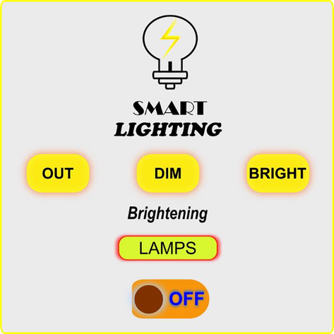
- The interface of the Android App. for controlling the smart street lighting.
3 Results and discussion
Ferroelectric materials show a hysteresis loop at their polarization curve when the external electric field change in direction or magnitude. This hysteresis because previous polarization contributes to present polarization. Our group has reported using the solution process to prepare thin-film BST, which was adopted in this report; the fabricated thin film showed the hysteresis loop characteristics (Hamdani et al., 2019). Those results prove that preparing the thin film of the ferroelectric material can be done using unsophisticated equipment and at a low cost; that is required in the mass production process.
As mentioned in literatures, ferroelectric materials possess high bandgap energy at blue to ultraviolet spectrum regions. This fact causes the electrons in the valence band is not possible to jump to the conduction band when illuminated by light with an energy lower than the blue color spectrum. However, researchers have proposed several explanations to explain the phenomenon of the ferroelectric thin film sensitivity to visible light (Borkar et al., 2017; Glass et al., 1974; T. Li et al., 2018; Y. Liu et al., 2017). The polarization phenomenon inside the ferroelectric material attributes to the improvement of the light sensitivity of ferroelectric-based devices. Other approaches have proposed are pores, orientation of domain walls, and impurities in the ferroelectric thin film enables the visible light absorbed to generate electron-hole pair (Bai, 2021; Han et al., 2021; Yang et al., 2010).
Growing the BST thin film on p-type Si will increase light sensitivity attributed to the polarization phenomenon. In addition, applying a bias voltage to the BST thin film for operation can force polarization and lead to fast separating electron holes to electrodes. P-type Si with a narrow band gap (∼1.12 eV) provides the electron-hole pair under visible light illumination. Later on, these generated electron-hole pairs will be separated by polarization in the BST and then move to the Al electrode. Moreover, the visible light illumination on the BST may change the electronic weight of the oxygen 2p orbital and then move oppositely to the Ti (4 + ). As a result, Ionics polarization will be created in the tetragonal crystal structures resulting in net charges. That is why varying mole fractions will obtain different relative displacements of ions in the tetragonal crystal structure.
Exposing the light to the surface of the BST thin film sensor causes a change in its resistance; it is because the electric field of the incident light induces relative ions displacement to create net charges. These net charges contribute to the charge transport mechanism in the BST thin film, therefore increasing the current. As a result of increasing the current, the resistance of BST thin film is decreasing.
The BST thin film resistance will get a slight change due to variations in receiving the light intensity, so a signal conditioning circuit is needed to observe the small-changing in the resistance of the BST thin film. The Wheatstone bridge is one of the circuits to detect the small changes in the resistance, as shown in Fig. 2. In this circuit, the voltage across the resistor R1 is slightly bigger (a few mV) than the voltage across the BST sensor when the light does not fall on the surface of the BST sensor. Using this setting will provide the voltage difference between the voltage across R1, and BST thin film is bigger when the light exposes the surface of the BST sensor. It is because of decreasing the voltage across the BST sensor due to dropping its resistance.
Sensitivity to light is an important characteristic of the light sensor that indicates how big the sensor responds to light. The more significant the sensor output change in response to changes in the intensity of light received indicates the sensor has high sensitivity and vice versa. The BST light sensor connected to the Wheatstone bridge circuit has the output in voltage. Changes in light intensity received by the BST sensor cause changes in the output voltage of the Wheatstone bridge. The comparison of changes in voltage to changes in light intensity of BST thin films with different mole fractions is shown in Fig. 6. The figure shows that the BST film with mole fraction × = 0.5 has the highest sensitivity of all the BST thin films made (Irzaman et al., 2016). It is also seen that the voltage bias condition to the BST thin film determines its sensitivity to light. Forward-biased BST thin film produces greater sensitivity to light than backward-biased condition (Mohammadmoradi et al., 2018). We suggested relatively low sensitivity in backward-biased due to expanding the space charge region or increasing the built-in electric field, hindering charge transport.
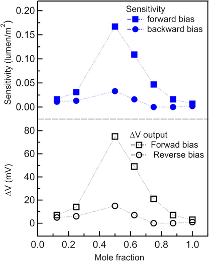
- Sensitivity and voltage difference as the response to light intensity changing from 2 lm/m2 to 450 lm/m2 for each BST thin film with varying mole fraction. The voltage in forwarding bias and reversing bias applied the BST thin film in the examination.
Another essential characteristic of the light sensor is the hysteresis characteristic. It ensures the sensor's output voltage is the similar when the sensor receives the same intensity even though the intensity changes from low to high or vice versa. BST thin film with mole fraction × = 0.5 exhibits the low hysteresis curve. The hysteresis index for BST thin-film with mole fraction × = 0.5 is 1.36 %, while for others BST thin-films with mole fraction x = 0.125; 0.250; 0.375; 0.625; 0.750; 0.875; 1.000 are 5.57 %, 0.52 %, 8.77 %, 39.92 %, 55.20 %, and 5.68 %, respectively. We assumed the low hysteresis originated from the thin-film paraelectric phase at room temperature. Where this phase observes at temperatures above the Curie temperature. As has been reported that the mole fraction close to 0.7 cause the Curie temperature around room temperature. (Lv et al., 2020).
As shown in Fig. 6, the change in the output voltage of the Wheatstone bridge circuit is 75 mV in response to changes in light intensity of 450 lm/m2. The magnitude of the voltage difference is the difference in the output voltage (79 mV) under conditions of maximum light intensity (452 lm/m2) and the output voltage (4 mV) under conditions of minimum light intensity (2 lm/m2). Using the OP-AMP amplifier circuit, the output voltage of the Wheatstone bridge circuit will be amplified before it is read by the 10-bit ADC port of the NodeMcu V3 microprocessor.
Having the small hysteresis index, that BST thin-film will guarantee the output voltage will similar at the particular light intensity and independent of changes in the light intensity from low to high or vice versa. The hysteresis curve of BST thin-film with mole fraction × = 0.5 and hysteresis index of each BST thin-film can be seen in Fig. 7.
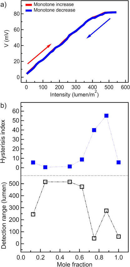
- (a) Output voltage of the BST thin film with mole fraction x = 0.5 vs light intensities, (b) hysteresis index and detection range of BST thin film with various mole fraction. Measurement output voltage in (a) conducted in two conditions; when the light intensity monotone increase (red-line) and monotone decrease (blue-line). Graph (a) shows the hysteresis characteristic of the BST thin film with mole fraction x = 0.5.
The range was determined based on the saturation condition of output voltage, either when the light intensity increases or decreases. The lowest intensity that causes saturation is the maximum intensity that the BST sensor can detect. That intensity is called the detection range of the BST sensor. Fig. 7 shows the detection range of each BST thin-films. It found that BST thin-films with mole fraction × = 0.25 and × = 0.5 had the highest detection range compared to other BST thin-films. Despite having the same detection range, BST film with × = 0.5 has sensing sensitivity-five times greater than BST film with × = 0.25. Therefore, for all the advantages possessed by the BST thin film with × = 0.5, this thin film is more appropriate to be utilized as a light sensor in the smart street lighting prototype.
We presume that the sensitivity and detection range of the BST thin films depends on their crystal structure which corresponds to the lattice constant. Meanwhile, the lattice constant is influenced by the atoms which occupy at corners of the tetragonal crystal structure-type structure. These atoms affect the facile and relative displacement of the titanium atom located at the center of the tetragonal crystal structure. Considering that reason, it can explain the BST thin film with mole fraction x = 0.5 has the best sensitivity and detection range compared to others.
The smart street light system has successfully implemented BST thin film with the mole fraction of x = 0.5 as a light sensor. The sensor provides an effortless for the maintainer to know the status of the lamp, whether on or off. If the light is detected to be off when it should be on, this system will send a report via SMS to the HP Android maintainer. The report contains information regarding the status of the damaged lamp and its IP address as an identity. This auto-reporting will help the maintainers determine the street-light that needs reparation and its position. Adding self-detecting and -reporting to the street lighting will significantly facilitate maintenance and, of course, reduce operational costs for routine checking of the street lights.
Time-status-based dimming is the main feature contributing to the energy efficiency of the smart street lighting system. The dimming of the lamps utilized the PWM 2000 AC module, which offers the ability to lower applied voltage to the lamps. The PWM 2000 AC module has a knob that can be rotated and has the functions to adjust the output voltage. The knob attaches to the arm of the servo motor module; so that the servo motor can rotate the knob (S2). In this smart street lighting system, the rules of the turning ON/OFF and dimming the lamp is 1) at 05:01 – 18:00, the lamps is turn OFF, 2) at 18:01 – 23:00, the lamps is turn ON at maximum intensity, 3) at 23:01 – 05:00, the lamps is turn ON in dim intensity. As shown in Table 1, the developed system could implement the rules to control the lamps for turning ON/OFF and dimming in automatically.
| Time (hour) | Condition lamp | Applied voltage to lamp (V) | Lamp power (watt) |
|---|---|---|---|
| 18:56 | ON / max. intensity | 205 | 22.30 |
| 00:02 | ON / dim intensity | 70 | 9.72 |
| 08:39 | OFF | 0 | 0 |
The smart street lighting system has a dimming feature that activates at certain times. Based on the comparison test of electrical energy consumption between lamps with dimming rules and lamps no dimming rules, lamps with dimming rules could save electrical energy by 69.23 %. Lamps equipped with dimming rules can save electrical energy consumption because during operation in 11 h, lamp power varies: at 18:01 – 23:00 (5 h) the lamp turns on with maximum intensity (22.30 W), while at 23:01 – 05:00 (6 h) the light is on with low intensity (9.72 W). In contrast to lamps with no dimming rules, these lamps are on in maximum intensity (22.30 W) in all operating time for 11 h. So that at the same length of the operation time, the electrical energy consumption by lamps with no dimming rules was more than lamps equipped with dimming rules (Matta & Mahmud, 2010; Shishegar & Boubekri, 2017).
Another feature of this smart street lighting system is that the maintainer can turn off or turn on certain street lights remotely via the Android application (Fig. 5). This remotely manual control can be activated by sliding the slider-button switch to the OFF position, then the three buttons: OUT, DIM, BRIGHT, LAMPS will be active. The OUT, DIM, BRIGHT, and LAMPS buttons have functions to turn off, turn on (dim intensity), turn on (maximum intensity), and selecting the street lamps, respectively, of street lamps. Meanwhile, to disable this manual control, the slider-button switch slide to the ON position, then the three lights setting buttons will be inactive. Then, the smart street lighting system will control the street lamps according to the dimming rules following dimming rules.
4 Conclusion
The ferroelectric sensor of the thin film BaxSr1-xTiO3 with mole fraction × = 0.500 has highly advantageous characteristics to be applied as a light sensor in smart street lighting systems. This thin film has the highest sensitivity, the smallest hysteresis, and the high detection range compared to other BST thin films. As a result, the BST light sensor has successfully assisted the prototype of the smart street lighting system to detect street lamps that need to be repaired and send the report to the maintainer. Furthermore, the developed prototype has saved energy usage by 69.23 % compared to conventional street lamps due to its ability to adjust the street-light intensity following the time-status-based dimming assigned to the microcontroller.
Acknowledgement
This work was financially supported by Hibah Program Riset Klaster Keilmuan - WCU LPPM IPB Univeristy, Indonesia grant number 9021/IT3.L1/PT.01.02/M/T/2021.
Declaration of Competing Interest
The authors declare that they have no known competing financial interests or personal relationships that could have appeared to influence the work reported in this paper.
References
- Intelligent street lighting in a smart city concepts—A direction to energy saving in cities: an overview and case study. Energies. 2021;14(11):3018.
- [CrossRef] [Google Scholar]
- Counterfeit band gaps caused by microstructural voids in photo-ferroelectric ceramics. Open Ceramics. 2021;5:100079
- [CrossRef] [Google Scholar]
- Properties of the barium strontium titanate film on the silicon substrate. Ferroelectrics. 2020;559(1):30-35.
- [CrossRef] [Google Scholar]
- Hysteresis loops and dielectric properties of compositionally graded (Ba, Sr)TiO 3 thin films described by the transverse Ising model. Chin. J. Phys.. 2016;54(4):533-544.
- [CrossRef] [Google Scholar]
- Bodur, H., Bakan, A. F., & Sarul, M. H. (n.d.). Universal motor speed control with current controlled PWM AC chopper by using a microcontroller. Proceedings of IEEE International Conference on Industrial Technology 2000 (IEEE Cat. No.00TH8482), 2, 394–398. https://doi.org/10.1109/ICIT.2000.854154.
- Optically controlled polarization in highly oriented ferroelectric thin films. Mater. Res. Express. 2017;4(8):086402
- [CrossRef] [Google Scholar]
- Cost analysis of smart lighting solutions for smart cities. IEEE Internat. Conf. Commun. (ICC). 2017;2017:1-6.
- [CrossRef] [Google Scholar]
- Printed Wheatstone bridge with embedded polymer based piezoresistive sensors for strain sensing applications. Addit. Manuf.. 2018;20:119-125.
- [CrossRef] [Google Scholar]
- Design of a CMOS monolithic digitized light detector with noise insensitivity for light monitoring applications. IEEE Sens. J.. 2014;14(8):2537-2545.
- [CrossRef] [Google Scholar]
- Influence of the polarization enhanced by barium strontium titanate and their surface modified fillers in the organic-inorganic composites of polyurethane based polycarbonate diol. Ferroelectrics. 2021;573(1):116-131.
- [CrossRef] [Google Scholar]
- Structure, dielectric properties and energy storage performance of barium strontium titanate thin films prepared by spin-coating technique. In: 2016 Joint IEEE International Symposium on the Applications of Ferroelectrics, European Conference on Application of Polar Dielectrics, and Piezoelectric Force Microscopy Workshop (ISAF/ECAPD/PFM). 2016. p. :1-4.
- [CrossRef] [Google Scholar]
- Home automation using GSM. In: 2011 International Conference on Signal Processing, Communication, Computing and Networking Technologies. 2011. p. :15-19.
- [CrossRef] [Google Scholar]
- Mechanistic study of metalorganic chemical vapor deposition of (Ba, Sr)TiO3 thin films. J. Appl. Phys.. 2000;87(10):7430-7437.
- [CrossRef] [Google Scholar]
- High-voltage bulk photovoltaic effect and the photorefractive process in LiNbO 3. Appl. Phys. Lett.. 1974;25(4):233-235.
- [CrossRef] [Google Scholar]
- A synthesis of BaXSr1-xTiO3 film and characterization of ferroelectric properties and its extension as random access memory. Mater. Phys. Mech.. 2019;42(1):131-140.
- [CrossRef] [Google Scholar]
- Tailoring of a visible-light-absorbing biaxial ferroelectric towards broadband self-driven photodetection. Nat. Commun.. 2021;12(1):284.
- [CrossRef] [Google Scholar]
- Ferroelectric and dielectric properties of strontium titanate doped with barium. Magnetism. 2021;1(1):22-36.
- [CrossRef] [Google Scholar]
- Chemical sensors based on a high-k perovskite oxide of barium strontium titanate. Procedia Eng.. 2014;87:28-31.
- [CrossRef] [Google Scholar]
- Multiparameter sensor chip with barium strontium titanate as multipurpose material. Electroanalysis. 2014;26(5):980-987.
- [CrossRef] [Google Scholar]
- Physical and pyroelectric properties of tantalum-oxide-doped lead zirconium titanate [Pb0.9950(Zr0.525Ti0.465Ta0.010)O3] thin films and their application for IR sensors. Physica Status Solidi (A). 2003;199(3):416-424.
- [Google Scholar]
- Electrical properties of photodiode Ba0.25Sr0.75TiO3 (BST) thin film doped with ferric oxide on p-type Si (100) substrate using chemical solution deposition method. Atom. Indonesia. 2011;37(3):133.
- [CrossRef] [Google Scholar]
- Characterization of Ba 0.55 Sr 0.45 TiO 3 films as light and temperature sensors and its implementation on automatic drying system model. Integr. Ferroelectr.. 2016;168(1):130-150.
- [Google Scholar]
- Application of lithium tantalate (LiTaO 3) films as light sensor to monitor the light status in the Arduino Uno based energy-saving automatic light prototype and passive infrared sensor. Ferroelectrics. 2018;524(1):44-55.
- [Google Scholar]
- Surface morphology properties doped RuO 2 (0, 2, 4, 6%) of thin film LiNbO 3. J. Phys. Conf. Ser.. 2019;1282(1)
- [CrossRef] [Google Scholar]
- Khwanrit, R., Kittipiyakul, S., Kudtonagngam, J., & Fujita, H. (2018). Accuracy Comparison of Present Low-cost Current Sensors for Building Energy Monitoring. 2018 International Conference on Embedded Systems and Intelligent Technology & International Conference on Information and Communication Technology for Embedded Systems (ICESIT-ICICTES), 1–6. https://doi.org/10.1109/ICESIT-ICICTES.2018.8442066
- Sol-gel synthesis of barium-strontium titanate in porous anodic alumina for uncooled IR detector. In: 2009 International Workshop Terahertz and Mid Infrared Radiation: Basic Research and Practical Applications. 2009. p. :25-26. 10.1109/TERAMIR.2009.5379647
- [Google Scholar]
- Application of barium strontium titanate (BST) as a light sensor on led lights. Ferroelectrics. 2020;554(1):160-171.
- [Google Scholar]
- Novel Low Melting Point Barium and Strontium Precursors for the MOCVD Growth of Barium-Strontium-Titanate Films. Chem. Vap. Deposition. 2009;15(10‒12):342-349.
- [CrossRef] [Google Scholar]
- Chemical Vapor Deposition of Barium Strontium Titanate Films with Direct Liquid Injection of Single-Mixture Solution. J. Electrochem. Soc.. 1999;146(10):3783-3787.
- [CrossRef] [Google Scholar]
- Optical control of polarization in ferroelectric heterostructures. Nat. Commun.. 2018;9(1):3344.
- [CrossRef] [Google Scholar]
- Synthesis of barium strontium titanate quasi photonic crystals with nanopore arrays by sol–gel technique. Integr. Ferroelectr.. 2016;176(1):202-209.
- [CrossRef] [Google Scholar]
- Structure and properties of barium strontium titanate nanoparticles synthesized by a hydrothermal method. Integr. Ferroelectr.. 2006;78(1):289-297.
- [CrossRef] [Google Scholar]
- Relaxation dielectric enhancement of barium strontium titanate ceramics by trace doping sodium niobate. Mater. Technol.. 2020;1–7
- [CrossRef] [Google Scholar]
- Ferroelectric polarization-assisted sensitive and high-power photodetector in broad ultraviolet-to-visible range. Adv. Opt. Mater.. 2017;5(12):1700158.
- [CrossRef] [Google Scholar]
- Manipulation of Curie temperature and ferroelectric polarization for large electrocaloric strength in BaTiO3-based ceramics. Ceram. Int.. 2020;46(10):14978-14984.
- [CrossRef] [Google Scholar]
- An intelligent light control system for power saving. In: IECoN 2010–36th Annual Conference on IEEE Industrial Electronics Society. 2010. p. :3316-3321.
- [CrossRef] [Google Scholar]
- Phasor Diagrams of Thin Film of LiTaO3 as Applied Infrared Sensors on Satellite of LAPAN-IPB. Procedia Environ. Sci.. 2016;33:615-619.
- [CrossRef] [Google Scholar]
- Strong composition dependence of resistive switching in Ba1-xSrxTiO3 thin films on semiconducting substrates and its thermodynamic analysis. Acta Mater.. 2018;148:419-431.
- [CrossRef] [Google Scholar]
- Morphological and structural properties of barium strontium titanate nanopowders synthesized via a sol-gel method. Ferroelectrics. 2020;554(1):30-37.
- [CrossRef] [Google Scholar]
- Investigation of the barium strontium titanate films on the silicon substrate. Ferroelectrics. 2021;575(1):117-122.
- [CrossRef] [Google Scholar]
- Elimination of circulating current in a parallel PWM rectifier using an interface circuit. IEEE Trans. Power Electron.. 2022;37(1):264-273.
- [CrossRef] [Google Scholar]
- Detection of magnetic nanoparticles using simple AMR sensors in Wheatstone bridge. J. Sci.: Adv. Mater. Devices. 2016;1(1):98-102.
- [CrossRef] [Google Scholar]
- Arduino and GSM based smart energy meter for advanced metering and billing system. In: 2015 International Conference on Electrical Engineering and Information Communication Technology (ICEEICT). 2015. p. :1-6.
- [CrossRef] [Google Scholar]
- IoT-based integrated smart home automation system. IEEE Trans. Power Electron.. 2022;37(1):341-355.
- [CrossRef] [Google Scholar]
- Quantifying electrical energy savings in offices through installing daylight responsive control systems in hot climates. Energy Build.. 2017;153:87-98.
- [CrossRef] [Google Scholar]
- Syafutra, H., Irzaman, Indro, M. N., Subrata, I. D. M., Khairurrijal, Abdullah, M., Srigutomo, W., Viridi, S., & Novitrian. (2013). Development of Luxmeter Based on Ba[sub 0,25]Sr[sub 0,75]TiO[sub 3] Ferroelectric Material. AIP Conference Proceedings, 1325, 75–78. https://doi.org/10.1063/1.4757193
- Teh, Y. C., Ong, N. R., Sauli, Z., Alcain, J. B., & Retnasamy, V. (2017). Barium strontium titanate (BST) thin film analysis on different layer and annealing temperature. 020290. https://doi.org/10.1063/1.5002484.
- Dielectric properties of atomic layer deposited thin-film barium strontium titanate. Integr. Ferroelectr.. 2008;102(1):29-36.
- [CrossRef] [Google Scholar]
- Visible light communications for sensing and lighting control. IEEE Sens. J.. 2016;16(17):6718-6726.
- [CrossRef] [Google Scholar]
- Above-bandgap voltages from ferroelectric photovoltaic devices. Nat. Nanotechnol.. 2010;5(2):143-147.
- [CrossRef] [Google Scholar]
- Rietveld analysis of ferroelectric PbZr0.525Ti0.475O3 thin films. Ceram. Int.. 2004;30(7):1483-1485.
- [CrossRef] [Google Scholar]
- Pulsed laser deposited ZrAlON films for high-k gate dielectric applications. Appl. Phys. A. 2005;81(6):1167-1171.
- [CrossRef] [Google Scholar]
Appendix A
Supplementary data
Supplementary data to this article can be found online at https://doi.org/10.1016/j.jksus.2022.102180.
Appendix A
Supplementary data
The following are the Supplementary data to this article:


