

Translate this page into:
Design of MEMS capacitive comb accelerometer with perforated proof mass for seismic applications
⁎Corresponding authors. suganthi.s@rajalakshmi.edu.in (S. Suganthi), mramamoorthy@ksu.edu.sa (Muthumareeswaran Muthuramamoorthy)
-
Received: ,
Accepted: ,
This article was originally published by Elsevier and was migrated to Scientific Scholar after the change of Publisher.
Abstract
Micro Electro Mechanical System (MEMS) sensors are characterized by their small size, but their performances exceed that of their macro-scale counterparts. The small size of MEMS devices and their integration with microelectronics proves a major advantage. In this paper, a design of MEMS capacitive comb accelerometer for seismology application using COMSOL Multiphysics platform is presented. A seismometer (also known as a seismograph) is a device that is used to measure and record the behavior of seismic waves. With this data, the location and measure of earthquakes can be detected. This seismic device has a large frequency band, compared to traditional geophones and seismographs. In this paper, a study to measure amplitudes and frequencies of vibrations is presented, and the results are analyzed and compared for perforated mass and solid proof mass. The effect of the size of etch hole for perforation is also studied. The displacement sensitivity and capacitive sensitivity of accelerometer are found to be 1.188 × 10⁻⁹m/g and 1.093 × 10⁻²¹F, respectively.
Keywords
Environmental quantity
MEMS
Sensors
Accelerometer
Seismology
Perforated mass
Etch hole
Proof mass

1 Introduction
Micro-Electro-Mechanical Systems (MEMS) sensors encompass a wide range of applications in all domains. The MEMS devices or systems are able to control, actuate and sense on the micro scale, and produce responses on the macro scale. The use of MEMS devices for various applications has seen an increase over the last decades. Over the traditional methods, the MEMS sensors are preferred because of their reduced dimension and weight, better long-term endurance, and their ease of handling. An accelerometer is a sensor that measures the acceleration or simply the vibration of a structure (Kavitha et al., 2016). Accelerometers can be used to determine the position and monitor the movement of the earth. It is done by converting a mechanical strain into an electrical signal (Xu et al., 2017). In addition, accelerometers accurately sense the change in inertia of automobiles and deploy the airbag within a fraction of a second. Other applications of the accelerometer are in aircraft and aviation industry for enhanced aerodynamic performance of turbines, compressors (Raaja-Bhaskaran et al., 2017). In military applications, micro accelerometers are used indistributed battlefield sensor net (DBSN) for accurate detection of targets. The integration of mechanical elements and electronic components reduces interference noise and avoids parasitic capacitances.
Accelerometers can be majorly classified as i) Piezoelectric ii) Piezoresistive and iii) Capacitive. Among these, the capacitive type is employed for seismology applications because of its high sensitivity, lower temperature coefficients, low power consumption, and excellent stability (Xu et al., 2017; Utz et al., 2018). Capacitive accelerometers with comb-drives i.e., interdigitated electrodes are used in a variety of MEMS sensors for inertial applications (Scudero et al., 2018).
MEMS accelerometers do not need a fixed reference for the measurement, they are used for the measurement of linear motion, and vibration (Varanis et al., 2018). The measurement of seismic motion is important for a wide range of applications in geology, civil structure monitoring, etc (Qu et al., 2008; Zhang et al., 2019). Replacement of the conventional seismometers that require vacuum sealing and hence are relatively very bulky, COMSOL Multiphysics®, a powerful simulation platform is used in this paper. From modelling the geometry, adding materials, defining physics, studying, all these can be done, and the results produced are accurate and trustworthy.
The MEMS comb-drive capacitive accelerometer was developed by researcher for use in SHM and seismic monitoring (Kavitha et al., 2016). The IntelliSuite MEMS modelling tool was used to simulate a surface micromachined capacitance comb drive accelerometer model. This was designed specifically for Structural Health Monitoring (SHM) applications in which low-frequency accelerations with high resolution are necessary.A piezoelectric accelerometer was developed specifically for SHM applications. (Raaja-Bhaskaran et al., 2017). A simple analytical model for MEMS cantilever beampiezoelectric accelerometer and high sensitivity design for SHM is discussed. The accelerometers must work at a lower frequency spectrum while still having a high sensitivity and a low noise floor. The drawback in this design is that the stability and sensitivity of the sensor when compared to the capacitive accelerometer the performance is lower.
Authors also designed a MEMS capacitive accelerometer with high precision and bandwidth (Utz et al., 2018). A low noise readout-IC and a high-precision bulk micro-machined sensing element are used in this accelerometer. The comparisons of various systems literature as well as commercial products are provided by the authors. Researchers developed a MEMS seismometer and geophones (Hou et al., 2021). As opposed to conventional instruments, the design is based on a small-scale seismometer, which would achieve greater sensitivity with a wider frequency range (Chen et al., 2013; Sabato et al., 2016; Tilli et al., 2020). The major drawback of this design is the limited proof mass for sensing, which has resulted in thermodynamic self-noise, which may impair the sensitivity (Mougenot and Thorburn, 2004; van Bakel, 2013; Laine and Mougenot, 2014; Peng et al., 2017).
2 Working principle
This comb-type capacitive accelerometer used in this work senses the change in capacitance with respect to acceleration. When vibration is being experienced, the proof mass anchored by the spring displaces and can move the combs attached to it with the same rate equal to the vibrations it sensed (Gupta and Mukherjee, 2000; Zhang et al., 2019). As a result of this, the distance between the plates (d) decreases. The capacitance (C) is inversely proportional to the distance between the plates (d) as seen in equation (1).
Where ε is the relativity permittivity. This change in capacitance is measured in volts as per the equation (2).
2.1 Design
2.1.1 Analytical design
The general analytical mass spring damper model of the accelerometer is as shown in (supplementary file) fig. S1:
The differential equation for the mechanical model is as follows:
Where, D is the damping coefficient, K is the spring constant, M is the proof mass, and ‘a’ is the acceleration applied externally. To obtain the second order transfer function, we use the Laplace transformation (Lynch et al., 2003):
For damped mass spring system, the quality factor Q is given by
Where ωr is the resonant frequency which is given by:
At low frequency (ω≪ωr) we have
Thus, the sensitivity is inversely proportional to square of resonant frequency. Lower ωr, higher the sensitivity. But it is limited by various factors (Trapani et al., 2012; Benmessaoud and Nasreddine, 2013) like mechanical shock resistance, Low spring constant, etc.
For the system, the inertial force is given as
From Hooke’s law
Equating the two forces we find that the displacement is given as:
From the Fig. 1, the capacitance when no acceleration is applied is given by:
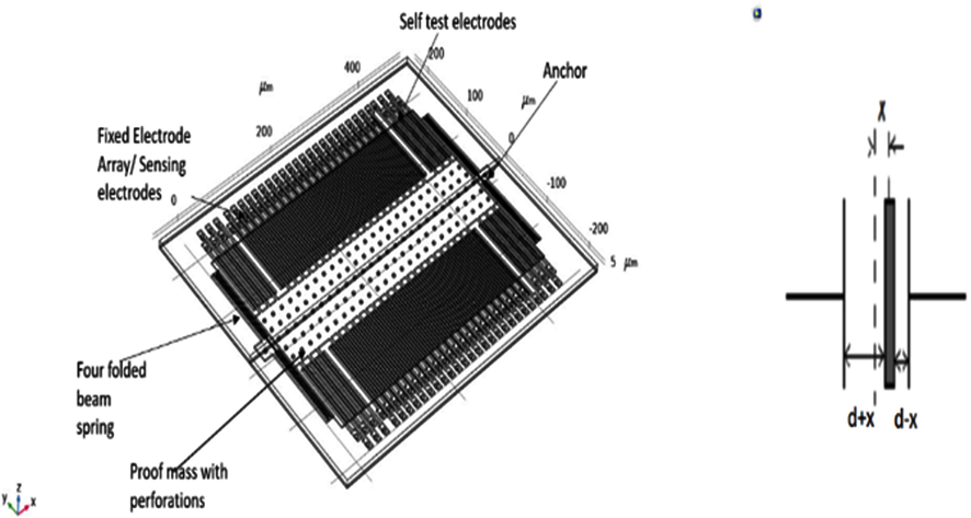
Structure of the accelerometer.
When acceleration is applied, the movement of fingers is opposite to that of the direction of acceleration applied, the capacitance changes. The left and right capacitances with respect to the plate are given as follows:
where, x is the displacement of the proof mass, A is the overlap area between all the electrodes in sensing area, ε is permittivity of air, d is the capacitance gap.
The differential capacitance of the accelerometer is as
From equations (14) and (17) we get
It is observed that the change in capacitance is directly proportional to acceleration ( .
2.1.2 Mathematical analysis
The spring constant of the structure is given by
Where E is the young’s modulus of polysilicon, h is the beam thickness, Wb is the beam-width, Lbis the length of the beam.For the proposed model it is calculated as 0.1567 N/m.
Due to the gap between the comb and the fingers, there occurs damping. The coefficient of damping can be given as follows:
Nf is total sensing finger number, neff is the effective viscosity of air, and do is capacitance gap.
2.1.3 Material used
Polysilicon is used for the proof mass, anchor, spring, and fingers in the proposed model. An air-box surrounds the entire polysilicon structure. The physics function called body load domain is used to apply an acceleration to this. The proof mass and its attached electrodes are at a floating potential whose value is determined by the position-dependent capacitance and the applied voltages on the fixed sense electrodes (Gonenli et al., 2011).
2.1.4 Geometry
The geometry is designed to the following specifications:
-
The dimensions of proof mass (L × W) are 448 × 200 μm.
-
There are 12 Self-test fingers and 42 Sense fingers on each side.
-
Each finger has a width of 4 μm and length of 114 μm.
-
The gap between the fingers is 1 μm.
-
For providing the perforations in the proof mass, it is etched to 4 μm size at a period of 18 μm.
-
The spring has (length × width × gap) of (280 × 2 × 1) μm.
-
The spring is connected with the anchor of 17 × 17 μm in size with radius of base 3 μm.
-
Short electrode has a length of 120 μm and long electrode has length of 140 μm.
-
The electrodes are attached with the pad of dimension 16 μm × 8 μm.
-
The finger overlap length is 104 μm. The total length is given by (length of proof mass+(2 × Length of spring assembly)).
2.1.5 Comparison with existing model
The geometrical parameters of the existing system (Kalaiselvi et al., 2020) and the proposed system is compared as shown in the (supplementary file) table s1.
Seismic applications require a high sensitivity accelerometer. Therefore, we need to increase sensitivity. As sensitivity is inversely proportional to the spring constant, it needs to be reduced. This can be done by making use of the folded beam structure (Xiong, 2005; Mistry et al., 2010; Zou et al., 2014).
2.1.6 Performance parameters
The following Table 1 shows the required parameter values for the design of seismic applications. z
Parameter
Optimum value
Model value
Noise spectral density
below 1 µg/√Hz
14.97 ng/√Hz
Resolution
Below 10-6 ms -2
10-9 ms -2
Sensor linearity
Linear at low power
The output is linear
Resonant frequency
Between 10-5 and 103 Hz
3 Results
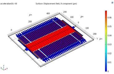
3.1 Study i: With perforated mass 4[μm] Etching & 18 [μm] period
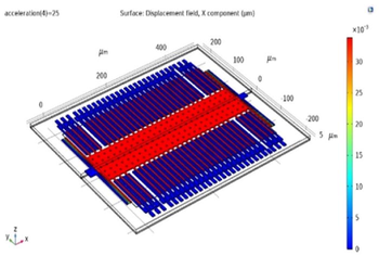
By applying acceleration in the range −50 g to + 50 g with 25 as step increment size, the change in the displacement occurring in the proof mass is analysed; the Fig. 2 depict the results.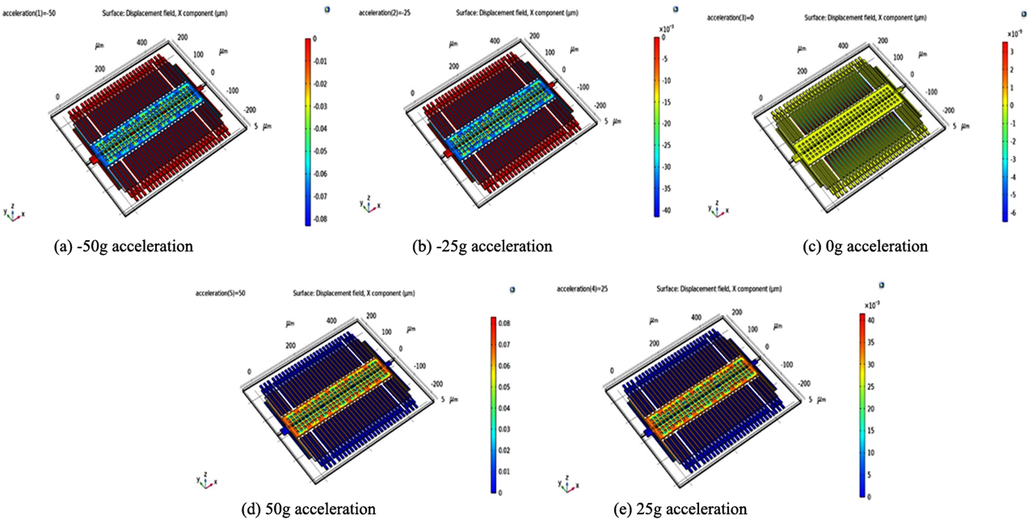
Simulation result with perforated mass: Displacement field for X component for −50 g (fig. a); −25 g (fig. b); 0 g (fig. c)25 g (fig. e) 50 g (fig. d) acceleration.
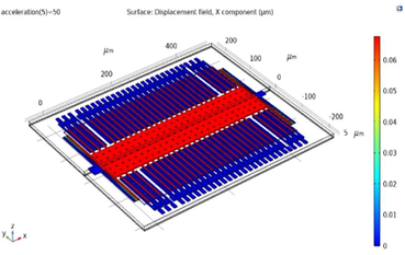
3.2 Study II:Without perforated mass
By applying acceleration in the range −50 g to + 50 g with 25 as step increment size, the result of the displacement occurring in the proof mass is analysed and the results depicts in Fig. 3.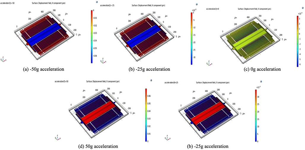
Simulation resultwithout perforated mass: Displacement field for X component for −50 g (fig. a); −25 g (fig. b); 0 g (fig. c)25 g (fig. e) 50 g (fig. d) acceleration.
As shown in Fig. 4, the set electrodes and the anchored spring bases shift very little. As anticipated, the springs have varying displacements along their length. In the actual unit, the potential at the fixed electrode is generated due to high frequency square wave that has opposite phase to that of the movable electrodes. These movable electrodes have a potential approximately equal to 50 % of supply voltage.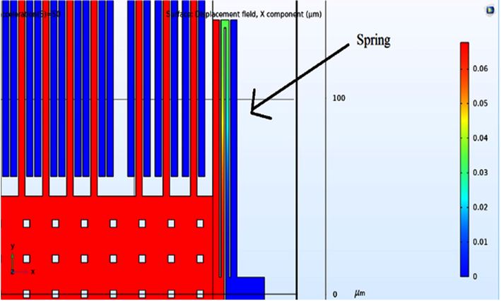
Varying displacement in spring along its length.
The fixed self-test electrodes are applied with a potential which is equal to half of supply voltage. Due to the applied acceleration, the proof mass displaces, this induces a capacitive coupling between the electrodes attached to proof mass and the set electrodes. As a consequence, an alternating voltage is caused. The above configuration eliminates the electrostatic force between the electrodes, thereby allowing the attached circuitry to process signals more efficiently.
The stationary component of the square wave is modelled in this case using a stationary analysis, which enables the problem to be solved easily. To electrostatic force between electrodes as mentioned earlier, is minimized by setting the bias to 0. It can also be done by dividing a factor of 1000 in the square wave amplitude. This factor is compensated by multiplying it back in the further processing.
The graph between displacement and the acceleration applied is illustrated in Fig. 5. From the graph we can see a linear relationship between the two parameters.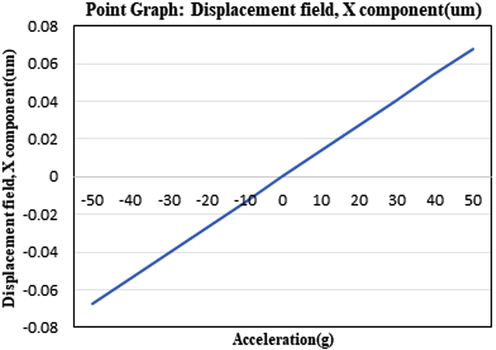
Point graph displacement field for × component.
3.3 Sense voltage vs acceleration
The sense voltage and acceleration have a linear relationship. This signal is fed into an amplifier, which was designed on the same substrate as the mechanical system in the actual unit. When the amplitude of the ac signal is changed, the bias is set at −40 to + 40 dc (Fig. 6).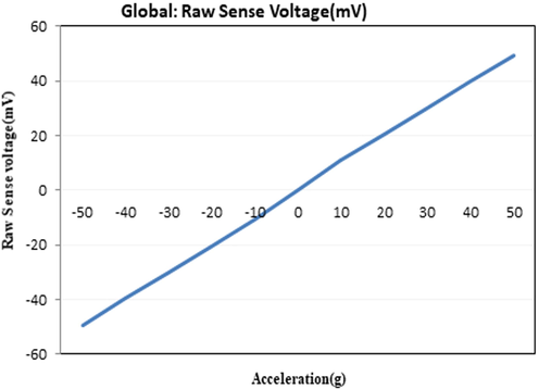
Raw sense voltage vs Acceleration.
The accelerometer’s self-test electrodes is designed for the self- testing purpose in factories. In the next study, a bias of 2 V is applied to the fixed self-test electrodes for the demonstration of self-testing applications.
The electrostatic force generated by the electric field between the fixed and moving electrodes allows the proof mass to shift. As voltage is applied, the displacement of the polysilicon domain is as seen in Fig. 6. It can be seen that the proof mass shifts by around 0.02 μm. In normal cases we see about 0.06 μm displacement. Hence it is optimum for self-testing purposes.
3.4 Comparison and analysis of simulation results
By changing the etch hole size and period in perforated proof mass, the observations are tabulated as follows in Table 2 and Table 3:
Property
Without perforated mass
With perforated mass
Property
Damping effect
Undesired as it affects the dynamic performanceHigh
Lower
Lowest
Mass
Ms Sensing massHighest
Reduces
Further reduces
Sensitivity
Sensitivity can be defined as the derivative of the output voltage or current with respect to the accelerationHigh
Optimal
Low
Study 1: With Perforated Mass 4 [µm] Etching and 8 [µm] Period
Study 1: With Perforated Mass 8 [µm] Etching and 16 [µm] Period
For 50 g acceleration, Proof mass displacement is 0.06 µm
For 50 g acceleration, Proof mass displacement is 0.08 µm
For 25 g acceleration, Proof mass displacement is 0.03 µm

For 25 g acceleration, Proof mass displacement is 0.06 µm
3.5 Effect of perforation of proof mass
In this system, the damping properties of air in the narrow gap greatly affects the dynamic performance of the system.The flow of air in the device is necessary. Otherwise, the particles move randomly causing Brownian noise (Due to Brownian motion). In order to reduce this air damping the perforations in proof mass is made.
However, we see that the Displacement sensitivity . So, as we use perforations, the mass of the structure is reduced, thereby decreasing the sensitivity. For seismology applications, sensitivity, should be in the order of 102 to mV m−1s 2 and bandwidth in range between 10−2 and 102 Hz.
Hence there is a need to maintain an optimum balance between these two parameters (sensitivity and damping) for this application. Therefore, the first study model has better performance, as none of the parameters needs to have a trade-off.
3.5.1 Significant outcome
MEMS accelerometer structures have a large surface area in comparison to their thickness. The efficiency of the system is affected by the damping properties of air in the narrow gap in these squeeze films. Brownian noise is the term for this kind of noise. This is calculated with the below equation.
Where,
µ is the Air viscosity (1.81 × 10⁻⁵Pa.s); L is the Finger overlap (104 μm); h is the Finger thickness (2 μm) and d is capacitance Gap (1 μm). Substituting we find that the noise is about B = 14.97 ng/√Hz.
Noise is also significantly diminished. This is because the proof mass has been perforated that reduces the air damping between the moving mass and the fixed electrodes.The sensitivity factor is also improved from the existing model which is as shown in Table 4.
Parameter/Model
Existing model
Proposed model
Displacement sensitivity
1.54x10⁻¹⁰ m/g
1.188 × 10⁻⁹ m/g
Capacitive sensitivity
7.85x10⁻¹⁸F
1.093 × 10⁻²¹F
4 Conclusion
This paper provides a system architecture modelling and sensitivity analysis of comb-type MEMS accelerometer for seismic applications. During an earthquake, the a point on the ground keeps changing in terms of its position and experienced forces. Under-water earthquakes are very small and originate at a distant location. So accelerometers with perforated proof-mass are capable of measuring and monitoring small acceleration signals generated by such earthquakes. Also detecting and continuous monitoring of “pre-seismic” on the ground can be enhanced by this technique. The obtained results indicate that the geometry of structure, such as the width and length of the movable fingers, and that of the spring has significantly improved the acceleration sensitivity. These results suggest that this accelerometer structure may be a good fit for low-frequency applications like seismology. With the help of the studies conducted, the optimized design has been achieved. The developed design can be developed into an integrated system for seismic studies.
Data availability
The raw/processed data required to reproduce these findings cannot be shared at this time as the data also forms part of an ongoing study.
Acknowledgment
The authors extend their appreciation to the Deputyship for Research & Innovation, Ministry of Education in Saudi Arabia for funding this research work through the project no. (IFKSURG-2-173).
Availability of data and material
Not applicable.
Code availability
Not provided.
Authors' contributions
The first author had explained the problem, helped in execution of the work and framed the manuscript. The second author was responsible for analysis of results, proof reading the manuscript. The contribution of third, fourth and fifth authors was in modelling and simulation of the proposed accelerometer.
Declaration of Competing Interest
The authors declare that they have no known competing financial interests or personal relationships that could have appeared to influence the work reported in this paper.
References
- Optimization of MEMS capacitive accelerometer. Microsys. Technol.. 2013;19(5):713-720.
- [Google Scholar]
- A micro electrochemical seismic sensor based on MEMS technologies. Sensor. Actuator A: Physical.. 2013;202:85-89.
- [Google Scholar]
- Surface micromachined MEMS accelerometers on flexible polyimide substrate. IEEE Sensors J.. 2011;11(10):2318-2326.
- [Google Scholar]
- MEMS based geophones and seismometers. Sensor. Actuat. A: Physical.. 2021;318:112498
- [Google Scholar]
- Analysis of damping optimization through perforations in proof-mass of SOI capacitive accelerometer. Analog Integr. Circ. S.. 2020;102(3):605-615.
- [Google Scholar]
- Design and analysis of MEMS comb drive capacitive accelerometer for SHM and seismic applications. Measurement. 2016;93:327-339.
- [Google Scholar]
- A high-sensitivity MEMS-based accelerometer. The Leading Edge.. 2014;33(11):1234-1242.
- [Google Scholar]
- Design of piezoresistive MEMS-based accelerometer for integration with wireless sensing unit for structural monitoring. J. Aerospace Eng.. 2003;16(3):108-114.
- [Google Scholar]
- Design of an SOI-MEMS high resolution capacitive type single axis accelerometer. Microsys. Technol.. 2010;16(12):2057-2066.
- [Google Scholar]
- MEMS-based 3D accelerometers for land seismic acquisition: Is it time? The Leading Edge.. 2004;23(3):246-250.
- [Google Scholar]
- A new type of tri-axial accelerometers with high dynamic range MEMS for earthquake early warning. Comput. Geosci.. 2017;100:179-187.
- [Google Scholar]
- A monolithic CMOS-MEMS 3-axis accelerometer with a low-noise, low-power dual-chopper amplifier. IEEE Sensor. J.. 2008;8(9):1511-1518.
- [Google Scholar]
- A Simple Analytical Model for MEMS Cantilever Beam Piezoelectric Accelerometer and High Sensitivity Design for SHM (structural health monitoring) Applications. Transact. Electric. Electron. Mat.. 2017;18(2):78-88.
- [Google Scholar]
- Wireless MEMS-based accelerometer sensor boards for structural vibration monitoring: a review. IEEE Sensor. J.. 2016;17(2):226-235.
- [Google Scholar]
- MEMS technology in seismology: A short review. In: 2018 Int. Conference Environ. Eng. IEEE; 2018. p. :1-5.
- [Google Scholar]
- Handbook of silicon based MEMS Materials and Technologies. Elsevier; 2020.
- Trapani, D., Biasi, N., De Cecco, M. Zonta, D., 2012. Validation of MEMS acceleration measurements for seismic monitoring with LVDT and vision system. 2012 IEEE Workshop on Environmental Energy and Structural Monitoring Systems (EESMS), IEEE, (pp. 104-109).
- A high-precision and high-bandwidth MEMS-based capacitive accelerometer. IEEE Sensor. J.. 2018;18(16):6533-6539.
- [Google Scholar]
- van Bakel, N., 2013. Silent sensors for stellar echo’s and seismic surveys, June.
- MEMS accelerometers for mechanical vibrations analysis: A comprehensive review with applications. J. Braz. Soc. Mech. Sci. Eng.. 2018;40(11):1-18.
- [Google Scholar]
- Built-in self-test and self-repair for capacitive MEMS devices. University of Cincinnati; 2005.
- Design and fabrication of a slanted-beam MEMS accelerometer. Micromachines.. 2017;8(3):77.
- [Google Scholar]
- A low noise capacitive MEMS accelerometer with anti-spring structure. Sensor. Actuator. A: Physical.. 2019;296:79-86.
- [Google Scholar]
- A seismic-grade resonant MEMS accelerometer. J. Microelectromech. Sys.. 2014;23(4):768-770.
- [Google Scholar]
Appendix A
Supplementary data
Supplementary data to this article can be found online at https://doi.org/10.1016/j.jksus.2023.102560.
Appendix A
Supplementary data
The following are the Supplementary data to this article:


