

Translate this page into:
Application of non-destructive geophysical methods for testing concrete structures
-
Received: ,
Accepted: ,
This article was originally published by Elsevier and was migrated to Scientific Scholar after the change of Publisher.
Peer review under responsibility of King Saud University.
Abstract
Non-destructive testing of reinforced concrete structures is of utmost importance in construction and civil engineering, where many factors can cause internal and external deterioration of reinforced concrete structures: the environment, nuclear radiation, and structural defects, among others. Geophysical non-destructive testing methods such as ultrasonic and radar have been increasingly used in civil engineering in recent years. Improvements in the ultrasonic testing of concrete have produced detailed images of the interiors of even the most complex structures and allowed for the earliest possible detection of deterioration. In this study, three geophysical methods were applied to inspect concrete structures: parallel seismic, sonic echo, and ultra-seismic. These three testing methods are applied to concrete foundations of two depths, namely 5, and 7 m; the deep foundation has a fracture at a depth of 4.5 m. The collected data are processed using a low-pass filter to remove the higher frequencies. These results of parallel seismic tests accurately predict foundation depths of 5.0 and 6.6 m and P-wave velocities of 2551 and 1097 m/s, respectively. Sonic echo tests yield depth predictions of 5.07 and 7.01 m for the tested foundations and 4.44 m for the depth of the crack. Meanwhile, ultra-seismic tests give depth predictions of 7.1 and 4.6 m for the foundation and fracture, respectively, while clarifying the P-wave velocities of the corresponding reflections: 3447 m/s exiting the 7-m foundation and 2668 m/s exiting the embedded fracture. Depth estimates based on each method show strong agreement with true depths. In conclusion, these three geophysical methods have great potential to provide quantitative data to drive quality assurance and remediation for concrete structures.
Keywords
Non-destructive testing
Parallel seismic
Sonic echo
Ultra-seismic
Concrete structures

1 Introduction
Heterogeneity in concrete is a major problem, whether in the form of fractures, cracks, aggregates, or other degradation features. Long-term exposure to severe weather conditions necessitates an assessment of the structural soundness and dependability of concrete. The type and strength of the degradation mechanism acting on the concrete structure determine the durability of the concrete structure, as do the structure’s resistance to degradation physical factors such as rheological processes, corrosion, crystallization, leaching, overload, fatigue, temperature, and humidity variation (Tosti et al., 2020; Catapano et al., 2020). Underlying factors include chemical mechanisms (carbonization, corrosion, corrosive environmental influence, material component reactions) and biological mechanisms (activities of plants, microbes, and animals in concrete structures) (Kim et al., 2003; Holä et al., 2015; Tosti and Ferrante, 2019). In practice, the combination of diverse mechanisms usually manifests as a complex degradation process that harms the structure and eventually defines its service life (Solla et al., 2019).
Corrosion of reinforcing steel is one of the key problems impacting the service life of reinforced concrete (RC). Such corrosion is caused by the damaging oxidation of the steel when exposed to harsh conditions, particularly chloride ions and/or carbon dioxide (Hasan and Yazdani, 2016, Teši et al., 2021). Due to the pressures exerted by the expansive oxide and the reduction or exhaustion of the adhesion between the reinforcement and the concrete, the consequences of the destructive action of oxidation present as a decrease in the steel cross-section, cracks in the concrete, and even lamination of the concrete (Prego et al., 2016). Internal flaws include voids and corrosion, while external defects include honeycombing, delamination, and rough surfaces. Numerous catastrophic outcomes can result from concrete defects, such as decreased load capacity and ductility, crack propagation, structural member failure, and collapse (Richart et al., 1928).
For these reasons, structural quality assessment is crucial. One of the most prevalent approaches to inspecting RC structures is non-destructive testing (NDT; Álvarez et al., 2023). In recent years, NDT methods have been used in a variety of engineering and geoscience fields (Almalki, 2015). Advancements in the application of electrical, electromagnetic, optical, and acoustic NDT methods have led to the establishment of their standalone use in many sectors. Many of these methodologies have now been thoroughly studied and evaluated (Wong et al., 2019). New theoretical advancements, improvements to hardware and software components, and the discovery of new surveying and data processing methods and interpretations have been the primary foci of research. Therefore, the quality of NDT results is now very high, and data can be captured quite precisely with current technology. The next scientific challenge on the horizon is to integrate sensing methodologies to significantly improve the capabilities of existing NDT technology in the face of new and complex scenarios. The need for more efficient methods to probe unusual situations is driving this development.
In the case of Italy, for example, every structure must conform to the Structure Act's basic standards for structures and other requirements, such as those pertaining to its intended use, throughout its lifetime (Vecchio and Bucci, 1999). Unfortunately, many concrete structures begin to show serious signs of degradation after only 20 to 30 years due to the combined action of mechanical and environmental influences. Such degradation occurs predominantly as a result of corrosion, and corrosion-related maintenance expenditures thus account for more than 3% of worldwide gross domestic product (GDP) annually.
In areas prone to earthquakes, rock falls, and soil deformation, a thorough geometric evaluation of the foundation can help ensure the safety of the structure. However, older structures’ architectural blueprints may not be readily available, casting doubt on claims regarding the depth of the foundation, the geometry of the structure, or the structure’s ability to withstand natural disasters. As a result, a reliable strategy must be implemented for evaluating the geometries of existing foundations. Ultrasonic measurements are used in fields as diverse as digital rock physics, well inspection, military and industrial equipment, and medicine (Meyers et al. 1960; Fry et al. 1962), among others. Recent years have seen significant advances in a number of ultrasonic techniques, making them increasingly essential for many problems in civil engineering involving the assessment of the condition of reinforced concrete (RC) structures. Some examples of this technology's many uses are flow detection (Bohs and Trahey, 1991), mapping internal objects or flaws (Schickert, 2005), and length assessment of concrete shafts following devastating earthquakes (Richard et al., 1998).
Alani and Lantini (2020), provide a summary of the literature that has been published on the topic of evaluating and tracking tree roots' interactions with the soil. The evaluation of the primary destructive and NDT methodologies points out a dearth of research-based outputs in the areas of soil interaction and tree-root interconnection. The application of non-invasive electromagnetic sensing technologies and civil engineering investigation techniques in tandem for the structural health monitoring of historical and cultural assets is covered by Ludeno et al. (2020). The capacity of GPR and linear variable displacement transducers (LVDT) to monitor the structural stability of historic buildings is the main topic of discussion. The use of these two methods to monitor cracking at the iconic Consoli Palace in Gubbio, Italy, is the subject of a case study. The findings show consistency between the LVDT and GPR methods' outputs as well as their ability to track the expansion and contraction cycles of cracking in masonry structures caused by seasonal temperature variations and, respectively, the geometry of the inner walls. Catapano et al. (2020) provide an overview of various electromagnetic imaging methods for applications in the field of cultural heritage, ranging from microwave to ultraviolet range of frequencies. Hoła and Sadowski (2022) are devoted to the identification of cracks in concrete Three different lenses and two digital cameras were used to record line images with a thickness of 0.1 to 0.5 mm. While other recent studies (Jeong et al., 2021; Javed et al., 2023; Dolati et al., 2023; Malla et al. 2023; Ortiz et al., 2023) examine the effectiveness of two of the most popular NDT techniques, phased array ultrasonic (PAU) and ground penetrating radar (GPR), in finding Fiber Reinforced Polymer FRP bars and strands embedded in concrete components.
The effectiveness of several ultrasonic techniques for estimating the lengths of undamaged or defective piles has been the subject of extensive field experiments. Drilled shafts were evaluated by Finno and Gassman (1998) using the impulse response technique. They showed that three factors all affect the method’s accuracy: the ratio of the shaft’s length to its depth, the ratio of the shear wave velocity of the surrounding soil to the propagation velocity of the concrete, and the soil stratigraphy. The reflection response of embedded flaws under the impact echo method was demonstrated in finite element research by Lin et al. (1997). They brought attention to the impact echo approach’s capacity to identify the presence of cracks, voids, and layers of low-quality concrete in concrete shafts. Lo et al. (2009) detailed an experimental technique for applying the parallel seismic (PS) method in estimating the depth of a foundation of unknown depth. The PS approach can non-destructively provide information regarding pile geometry and depth at a low cost (Olson et al., 1996; Ni et al., 2011). For the determination of unknown bridge foundation depths, Olson (2003) showed that the PS and ultra-seismic (US) methods were generally applicable to both borehole and surface methods.
Through the current study, three global and worldwide geophysical methods; PS, US, and sonic echo (SE) of non-destructive testing (NDT) have been applied to concrete structures in the King Abdulaziz City of Science and Technology (KACST) testing site (Fig. 1a) in order to; i) identify internal concrete fractures/cracks and ii) determine the actual depths of the tested foundations.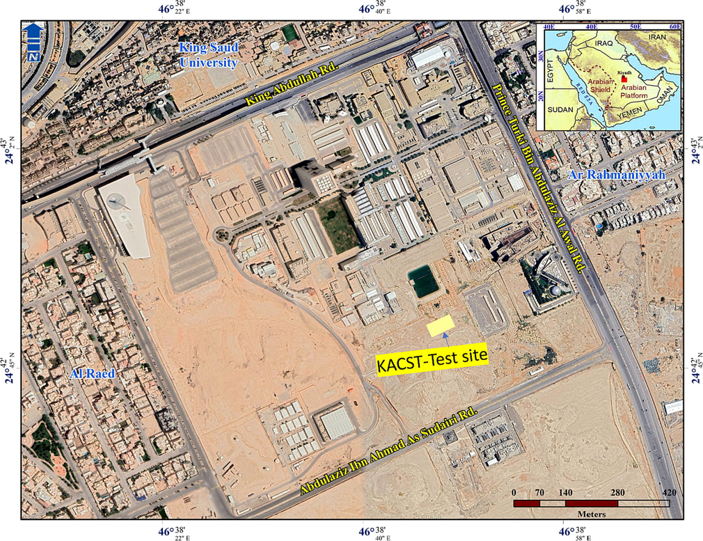
GIS-based map of KACST test site.
2 Material and methods
The fundamentals of the used methods PS, US, and SE are outlined in Fig. 1b following the American Concrete Institute recommendations (ACI.228.2R-98, 2004). The principle of each method is discussed and the typical instrumentation is described. The testing procedures are summarized and the data analysis methods are explained. The advantages and limitations of the methods are highlighted in ACI 228.2R-98 (2004). The methods used in this study are non-destructive testing methods that have been used recently in the quality control of concrete structures such as columns and sidewalks. These methods have been selected based on recommendations from civil and geotechnical engineering experts due to an urgent need to evaluate the conditions of structures and rehabilitation studies, and due to the increased demand for assessing and determining the quality of large engineering projects and prefabricated structures.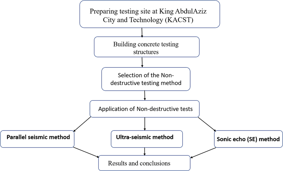
Flowchart methodology of the current study.
2.1 Parallel seismic method
Borehole seismic methods such as the PS technique are utilized to determine the depths of foundations of unknown depths. Researchers at the Center for Experimental Research and Studies of Building and Construction developed the PS method in the mid-1970s (Lo et al., 2009). Several publications, including Olson (2003) and Olson et al. (2006), have provided exhaustive descriptions of this testing technique. The PS method necessitates the installation of a 2.32-inch slanted cased borehole (i.e., ASTM D 4428/D 4428 M) adjacent to the foundation in order to conduct the necessary tests. The borehole is subsequently filled with water (or left empty when employing a 3-component (3C) geophone) in order to detect the radiated waves with a hydrophone. The stress waves are generated by an external force delivered by an instrumented hammer to the top or any accessible area of the foundation; these waves then travel down the foundation and are picked up by a hydrophone in the borehole. Hydrophones are placed at regular intervals along the borehole in order to collect data at various depths. Repeating the source (here, an impact hammer) at multiple measurement sites and stacking the resulting data can increase the signal-to-noise ratio. The collected information is used to create a signal-versus-depth diagram (Fig. 2). In most cases, the depth of a structure’s foundation can be estimated based on the intersection point, on a travel-time plot, of the foundation velocity line and the soil velocity line (Liao et al., 2006).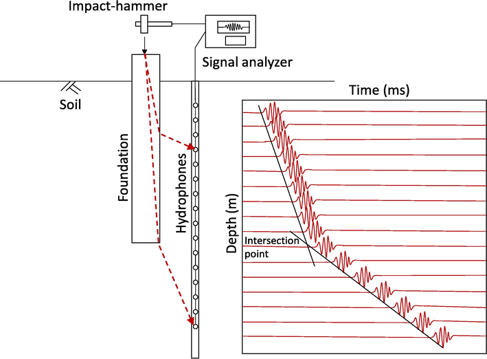
A schematic of Parallel Seismic test procedure. The travel time-depth plot (right) shows the intersection point where the depth of the foundation may occur.
2.2 Ultra-seismic method
The data generation and acquisition processes of the US method require a relatively tall exposure of the foundation: 1.5–2 m. US measurements are taken using a 3-component accelerometer and an impulse hammer. The data can be collected from the accelerometer by inserting it on any side of the base. As can be seen in Fig. 3, the impact hammer is always sited at the topmost part of the column, and the time–depth profile is constructed by repeating the test at various accelerometer positions along the accessible vertical profile. The existence of internal defects is determined by demonstrating an intersection point between the first arrivals (also known as wave velocity within the foundation) and reflected energy from the bottom or any portion of the foundation. Conventional methods for analyzing geophysical borehole data are adapted for use with the US approach (Jalinoos and Olson, 1996). Processing steps include an automatic gain control, a band-pass filter operating from 0 to 0.5 and from 3 to 4 kHz, and the elimination of DC shift.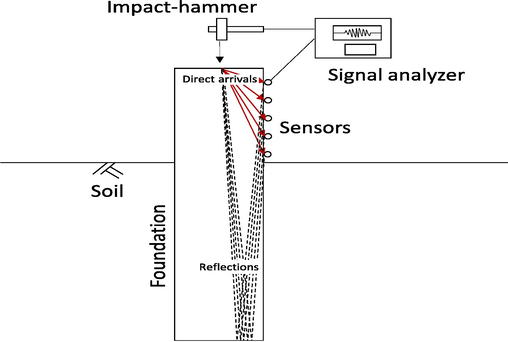
A schematic of Ultra- Seismic test geometry. Direct and reflected waves are recorded using three-component accelerometers mounted at regular intervals on the accessible side of the foundation. The source (impulse hammer) is located at the top of the foundation.
2.3 Sonic echo (SE) method
SE, one of the earliest approaches to use reflected stress waves to practically estimate the depths of foundations, identifies stress wave parameters, namely wave velocity, and reflection duration. The impact hammer’s strike on the top of the foundation generates compressional waves (Fig. 3), which travel the length of the foundation and reflect back from any discontinuity. Such discontinuities may represent the bottom of the foundation or locations with anomalous acoustic impedance. A velocity transducer (geophone) attached to the foundation head measures vibrations (Fig. 4).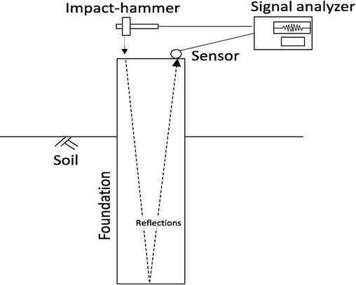
The source and receiver location for the sonic echo method for accessible foundation top.
Then the following equation is used to estimate the foundation depth D based on the speed of compressional waves Vp traveling through the foundation and the time difference (t) between the first arrival waves and the reflected waves from the discontinuity.
For concrete structures, Vp can range from 3,500 to 4,500 m/s depending on factors including age, quality, and composition (Popovics, 1994). In practice, sound propagates through high-quality concrete at ∼ 4000 m/s, but the propagation velocity in low-quality concrete is only ∼ 2000–3000 m/s. In this way, engineering geophysical approaches allow for the straightforward detection of defects in concrete.
3 Results and discussion
The NDT test site at King Abdulaziz City for Science and Technology was used for the experimental study of non-destructive geophysical methods. For down-hole seismic testing, the site features a poly (vinyl chloride) inclined cased borehole built in accordance with ASTM requirements (D 4428/D 4428 M) (Figs. 5 and 6). Two concrete foundations with effective depths of 5 and 7 m were poured to finish the site. A crack volume of 25 × 25 × 5 cm, representing 30% of the total volume of the foundation, was prepared at a depth of 4.5 m within the foundation desgined deeper with 7m depth.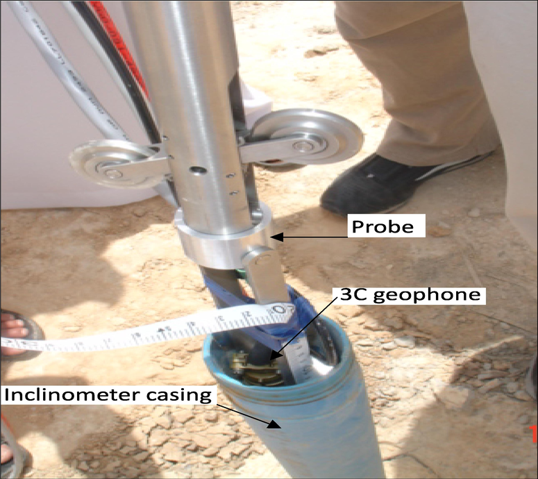
Inclinometer PVC pipe used for preparing the borehole set for Parallel Seismic test. The insertion of a 3C geophone probe through the PVC pipe is illustrated.
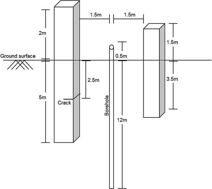
Schematic plan for the tested structures at the test site.
A field test is conducted to determine the viability of the PS approach by verifying the depth of the shallower of the two foundations. Seismographic data from a 5-m-deep PS test are displayed in Fig. 7. A 3C geophone shown in Fig. 6 is installed in a borehole with uniform geophone spacing of 0.5 m from ground level to a depth of 8 m below ground level. The foundation depth was interpreted using the straight-line fitting methods previously discussed. The fitting approach predicted velocities of 2551 and 1097 m/s and a foundation depth of 5.02 m, which closely matched the actual depth of the foundation.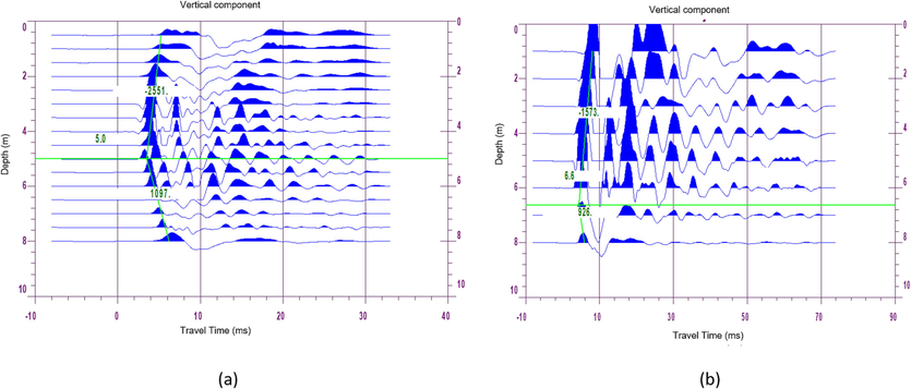
Time-depth profile for Parallel Seismic PS test acquired for a pre-designed foundation with 5 and 7 m depth. (a) The intersection point associated with the foundation depth is illustrated at 5.0 m depth. (b) The intersection point associated with the foundation depth is illustrated at 6.6 m depth. Each trace represents the wavefield acquired from different borehole depths.
The features of the wave field received from the bottom of the foundation and the embedded fracture were analyzed using the US method. Fig. 2 depicts the foundation from the accessible side, while Fig. 8 displays a multi-channel recording of the downward and upward wave fields.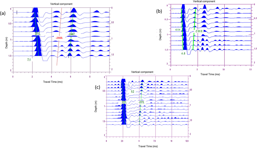
Ultra-Seismic profile was acquired using the vertical component of the 3C accelerometer. The data were recorded over ten positions along an exposed foundation surface at regular accelerometer spacing of 10 cm. (a) The cross-section of two straight lines of direct and reflected waves (green lines) indicates the foundation depth at 7.1 m. (b) The reflections associated with the foundation fracture were observed at a depth of 4.5 m. (c) Two straight lines of direct and reflected waves (green lines) indicate the foundation depth at 5.2 m.
A 3C accelerometer was utilized to collect the information along a 15-cm vertical profile. Signals from the vertical component are shown in Fig. 7, with each trace representing a unique foundation measurement. The reflections from the bottom of the foundation and the embedded fracture, traveling at 3447 and 2668 m/s, respectively, were able to be distinguished and identified as coming from different locations due to the different amount of time it took for each reflection to arrive. Straight-line fitting methods for down-going waves (direct arrivals) and up-going waves (reflections from the foundation bottom and the embedded fracture) yielded predicted depths of 7.1 m for the 7-m-deep foundation and 4.6 m for the fracture zone at an actual depth of 4.5 m.
Predicting reflections from embedded imperfections is difficult without the US approach’s precise measurement. This research shows that the quality of the data collected depends heavily on how securely the accelerometer is coupled to the test surface. Therefore, grease was used to attach the accelerometer to the basement wall, providing a flat surface for testing and ensuring proper coupling.
Next, SE tests were performed on the tops of two foundations with depths of 5 and 7 m to determine their true depths (Figs. 9 and 10). The data, processed using a low-pass filter to remove the higher frequencies, yielded predicted foundation depths of 5.07 and 7.01 m deep, respectively, based on Eq. (1). These predicted depths agree strongly with the true depths.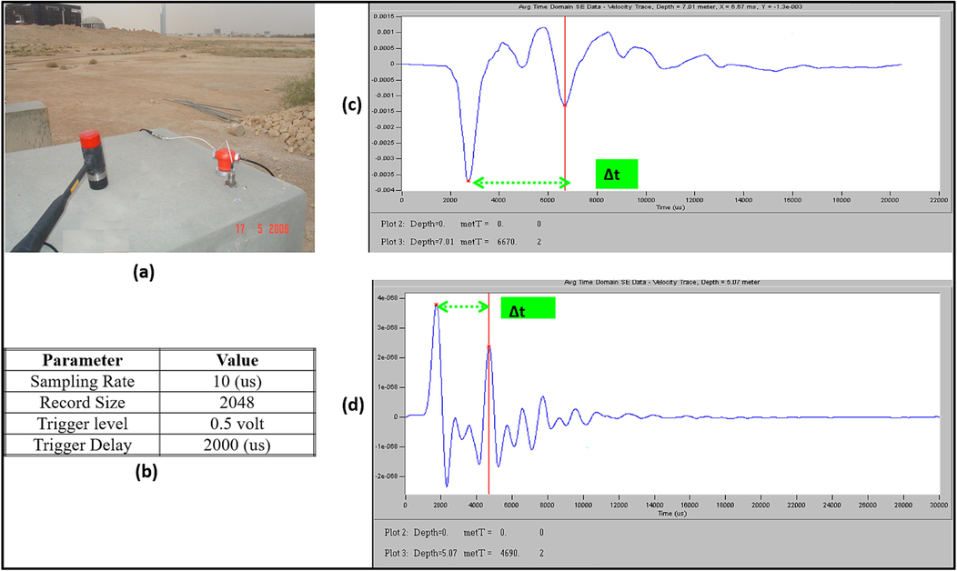
The sonic echo data from the reinforced foundation with; a) field data acquisition, (b) the acquisition parameters, (c)and is data with a nominal depth of 5 m, and (d) data with a nominal depth of 7 m.
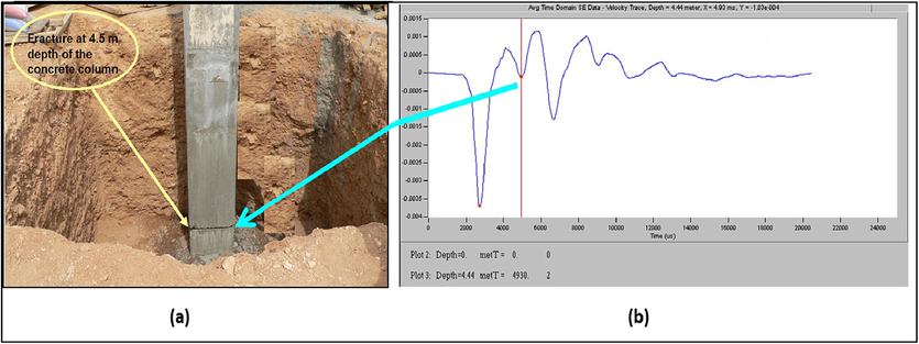
The sonic echo data from the fracture at a depth of 4.4 m, where it is detected at 4.44 m depth.
4 Conclusions
Three NDT techniques were applied to concrete foundations of two different depths: 5.0 and 7.0 m; the deep foundation had a fracture at a depth of 4.5 m. The higher frequencies were eliminated from the gathered data by applying a low-pass filter during processing. PS testing results predicted velocities of 2551 and 1097 m/s for the foundation depth and the surrounding soil and foundation depths of 5.0 and 6.6 m, respectively. SE testing predicted foundation depths of 5.07 and 7.01 m, respectively, for these same two foundations. Furthermore, SE testing predicted a depth of 4.44 m for the fracture zone was in depth. The US testing approach estimated that reflections left the 7-m foundation at a P-wave velocity of 3447 m/s but left the embedded crack at a velocity of 2668 m/s. US testing predicted depths of 7.1 and 4.6 m, respectively, for the 7-m-deep foundation, and the fracture zone at a depth of 4.5 m. According to these results, the predictions of all three approaches show significant agreement with the actual depths of foundations and fracture zones. These three geophysical methods thus show great potential for providing quantitative data about concrete structures to drive quality assurance and remediation efforts. Based on the results obtained, it is recommended that use these methods in the evaluation and remediation of concrete structures where they are more operative and useful due to their cost-effectiveness. Activating these methods will help to localize modern technologies and provide confidence to both engineers and facility owners.
Acknowledgments
This work was supported by the King Abdulaziz City for Science and Technology (KACST). The author thanks Dr Khaled Almutairi and Hashem Almalki from KACST for their assesstance during test site preparation, and Dr Larry Olson from Olson Engineering Co., for his support during data acquisition.
Declaration of competing interest
The authors declare that they have no known competing financial interests or personal relationships that could have appeared to influence the work reported in this paper.
References
- Recent advances in tree root mapping and assessment using non-destructive testing methods: a focus on ground penetrating radar. Surv. Geophys. 2020
- [CrossRef] [Google Scholar]
- Experimental Study of Nondestructive Geophysical Methods for Evaluating the Condition of Concrete Structures. ASEG Extended Abstracts. 2015;2015(1):1-4.
- [CrossRef] [Google Scholar]
- A novel method for angle independent ultrasonic imaging of blood flow and tissue motion. Biomedical Engineering, IEEE Transactions on. 1991;38(3):280-286.
- [Google Scholar]
- Noninvasive analytical and diagnostic technologies for studying early renaissance wall paintings. Surv. Geophys. 2020
- [CrossRef] [Google Scholar]
- Evaluating the Effects of Loading Protocol on the Strength and Deformation Capacity of Flexure-Shear Critical Concrete Columns. Eng. Struct.. 2023;2023(279):115592
- [Google Scholar]
- Impulse response evaluation of drilled shafts. Journal of Geotechnical and Environmental Engineering, ASCE. 1998;124(10):965-975.
- [Google Scholar]
- Tissue interface detector for ventriculography and other applications. J. Neurosurg.. 1962;19(9):793-798.
- [Google Scholar]
- An Experimental Study for Quantitative Estimation of Rebar Corrosion in Concrete Using Ground Penetrating Radar. Hindawi Publishing Corporation.. 2016;2016:8.
- [Google Scholar]
- Non-destructive and Semi-destructive Diagnostic of Concrete Structures in Assessment of Their Durability. Bull. Acad. Pol. Sci.. 2015;63:87-96.
- [Google Scholar]
- Non-Destructive Testing in Civil Engineering. Appl. Sci.. 2022;2022(12):7187.
- [CrossRef] [Google Scholar]
- Jalinoos, F., and Olson, L. D., 1996, Determination of unknown depth of bridge foundation using nondestructive testing methods, In Proceeding, The Structural Materials Technology- An NDT conference, San Diego, CA.
- Micro-Scale Experimental Approach for the Seismic Performance Evaluation of RC Frames with Improper Lap Splices. Infrastructures. 2023;2023(8):56.
- [Google Scholar]
- Analysis of Fine Crack Images Using Image Processing Technique and High-Resolution Camera. Appl. Sci.. 2021;2021(11):9714.
- [Google Scholar]
- Kim, W., Ismail, A.. Anderson, N.L., Atekwana, E.A., Buccellato. 2003. A. Non-destructive Testing (NDT) for Corrosion in Bridge Decks Using GPR. In Proceedings of the 3rd International Conference on the Application of Geophysical Methodologies and NDT to Transportation Facilities and Infrastructure, Geophysics 2003, Orlando, FL, USA.
- Measurement of unknown bridge foundation depth by parallel seismic method. Exp. Tech.. 2009;33(1):23-27.
- [Google Scholar]
- Ludeno G, Cavalagli N, Ubertini F, Soldovieri F, Catapano I (2020) On the combined use of ground penetrating radar and crack meter sensors for structural monitoring: application to the historical Consoli Palace in Gubbio, Italy. Surv Geophys. https://doi.org/10.1007/s10712-019-09526-y.
- Feasibility of Conventional Non-Destructive Testing Methods in Detecting Embedded FRP Reinforcements. Appl. Sci.. 2023;2023(13):4399.
- [CrossRef] [Google Scholar]
- Determinations of topologic human brain representations and modifications of signs and symptoms of some neurologic disorders by the use of high-level ultrasound. Neurology. 1960;10:271.
- [Google Scholar]
- Inclination correction of the parallel seismic test for pile length detection. Comput. Geotech.. 2011;38(2):127-132.
- [Google Scholar]
- Borehole NDT techniques for unknown subsurface bridge foundation testing. In: Nondestructive evaluation of bridges and highways. AZ, United States: Scottsdale; 1996. p. :10-16.
- [Google Scholar]
- Olson, L. D., 2003, Determination of unknown bridge foundation depths with NDT methods, proceeding of 82nd annual TRB meeting, paper no.03-4039.
- FRP-Reinforced/Strengthened Concrete: State-of-the-Art Review on Durability and Mechanical Effects. Materials. 2023;2023(16):1990.
- [Google Scholar]
- A Survey of Developments in Ultrasonic NDE of Concrete. IEEE Transactions of Ultrasonics, Ferroelectrics, and Frequency. Control.. 1994;Vol. 41, No. 1:January.
- [Google Scholar]
- Assessing the Applicability of Ground-penetrating Radar to Quality Control in Tunneling Construction. ASCE. 2016
- [Google Scholar]
- Impulse Response Evaluation of Drilled Shafts, Journal of Geotechnical Geoenvironmental. Engineering. 1998;124(10):965-975.
- [Google Scholar]
- Richart, F.E., A. Brandtzaeg, and R.L. Brown, A study of the failure of concrete under combined compressive stresses. 1928, University of Illinois at Urbana Champaign, College of Engineering.
- Assessing Rebar Corrosion Through the Combination of Non-destructive GPR and IRT Methodologies. Remote Sens. (Basel). 2019;11
- [Google Scholar]
- Non-Destructive Corrosion Inspection of Reinforced Concrete Using Ground-Penetrating Radar: A Review. Materials. 2021;2021(14):975.
- [CrossRef] [Google Scholar]
- Using Ground Penetrating Radar Methods to Investigate Reinforced Concrete Structures. Surv. Geophys. 2019 Springer
- [CrossRef] [Google Scholar]
- Analysis of Repaired Reinforced Concrete Structures. J. Struct. Eng.. 1999;125:644-652.
- [Google Scholar]
- Wong, T. W., Lai, W. W., Sham, J. F., Poon, C. 2019. Hybrid Non-destructive Evaluation Methods for Characterizing Chloride-induced Corrosion in Concrete. NDT and E International 107 (2019) 102123. https://doi.org /10.1016/j.ndteint.2019.05.008.
Appendix A
Supplementary data
Supplementary data to this article can be found online at https://doi.org/10.1016/j.jksus.2023.102916.
Appendix A
Supplementary data
The following are the Supplementary data to this article:


