

Translate this page into:
Advanced thermal management system of Lithium-Ion Batteries: Integrating thermoelectric modules with phase change materials
-
Received: ,
Accepted: ,
This article was originally published by Elsevier and was migrated to Scientific Scholar after the change of Publisher.
Abstract
This study investigates an innovative approach to lithium-ion battery thermal management using thermoelectric (TEC) modules and phase change materials (PCMs). The system incorporates battery enclosures filled with PCMs to stabilize temperature fluctuations. These enclosures are immersed in a water reservoir where the heat from the batteries is absorbed by the PCMs, which subsequently transfer heat to the surrounding water. A TEC cooling system then cools the water, completing the heat dissipation cycle. Experimental results show that this integrated system effectively reduces battery temperatures, achieving temperature reductions of approximately 12% for 50-watt, 9% for 30-watt, and 14% for 10-watt battery modes compared to natural convection methods. This approach not only enhances battery performance but also proves suitable for applications requiring compact and efficient thermal management solutions, such as electric vehicles.
Keywords
Battery thermal management
Lithium-ion battery
Thermoelectric
Electric vehicles

Data availability
Data will be made available on request.
1 Introduction
The process of cooling lithium-ion batteries (LIBs) holds significant importance due to the inverse relationship between battery temperature and its lifespan, where an increase in temperature leads to decreased longevity and accelerated failure. Elevated battery temperatures can adversely affect operational efficiency and safety, potentially leading to battery explosions. Optimal performance of LIBs is observed between 20 and 40 degrees Celsius, making it critical to maintain proper battery temperature (Y. Zhang et al., 2020). Performance diminishes once the battery's temperature exceeds 40 °C, and substantial lifespan reduction occurs above 60 °C (Thawkar & Dhoble, 2023).
Extensive research has been conducted on LIB cooling for electric vehicles (Dilbaz et al., 2024; Mokashi et al., 2022; Oyewola et al., 2023). Studies by Akinlabi and Solyali (2020) demonstrated that while natural convection for cooling LIBs is straightforward, it is not viable. They proposed forced convection through active air circulation, though it reduces cooling efficiency due to energy expenditure. Behi et al. (2020) introduced a hybrid model combining air cooling and heat pipes, achieving a 42.7 % reduction in battery temperature compared to natural convection.
However, air cooling is generally considered less effective for battery thermal management (Sikarwar et al., 2023; Zhao et al., 2022). Youssef et al. (2022) presented a passive cooling system using phase change materials (PCM) to cool electric vehicle batteries, achieving a temperature reduction of up to 35 °C. WafirulHadi et al. (2021) integrated heat pipes and PCM, significantly lowering battery temperatures. Liquid cooling has been widely investigated, demonstrating superior thermal efficiency (Garud et al., 2023; Khan et al., 2022).
Rao and Wang (2011) reviewed environmentally friendly automobile advancements and high-capacity energy storage batteries, focusing on PCM-based battery thermal management systems (BTMS). Challenges such as low thermal conductivity, increased weight, and leakage issues were noted. Wang et al. (2016) compared air cooling, liquid cooling, PCM, and heat pipe cooling methods, suggesting the selection of BTMS technology based on specific cooling demands. Liquid cooling is ideal for large-scale battery applications with high temperature and charging/discharging rates. Kim et al. (2019) explored additional cooling methods, including PCM-based, refrigerant two-phase, and thermoelectric (TEC) element cooling. Liu et al. (2017) emphasized enhancing BTMS systems for improved Li-ion battery performance and safety.
Mostafavi and Jain (2020) investigated the use of TECs for cooling Li-ion batteries, demonstrating significant reductions in core and surface temperatures. Their experimental results showed a temperature drop of 10 °C for a 0.75A TEC current, highlighting the potential for TECs in battery thermal management.
C. Zhang et al. (2020) conducted discharging experiments using TAFEL-LAE895 100Ah ternary Li-ion batteries and found that combining heat pipes with TEC coolers effectively reduces surface temperature. Their findings show that the combined system can maintain desired temperature ranges even at high discharge rates.
The novel model introduced in this study integrates liquid cooling, TEC modules, and PCM to form a hybrid approach. This model offers reduced weight and volume compared to alternative methods, making it suitable for applications with space constraints, such as electric vehicles. The proposed system demonstrates significant temperature reductions, improving battery efficiency and longevity. Unlike previous models, this study highlights the synergistic effect of combining these three cooling technologies, addressing the limitations of each method and presenting a more efficient and compact solution for battery thermal management.
2 Laboratory model
This study introduces two battery thermal management system models that incorporate the utilization of TEC modules for the purpose of battery cooling. To assess the proposed models and facilitate their comparative analysis, a representative sample has been generated. The initial design incorporates battery cells housed within a cylindrical aluminum casing. The gap between the shell and the battery body is filled with PCM, which enhances heat transfer and helps maintain a uniform temperature for the battery body. The hermetically sealed shell assembly is positioned within the water tank (Fig. 1-a). All the thermophysical properties of the materials used in this study are given in Table 1. In accordance with the research conducted by Lyu et al. (2019), the construction of these models involves the utilization of cylindrical structures resembling batteries rather than actual batteries. These cylinders are equipped with an electric heater, enabling the simulation of the heat generated by the battery. The TEC module is positioned within the upper region of the tank, with its cold side situated internally. In order to enhance the thermal conductivity between the water and the TEC, a heatsink featuring rectangular fins has been employed, and the connection between the heatsink and the TEC module has been established using silicone paste. Furthermore, the TEC module's hot side is effectively linked to a heatsink, while the entire arrangement is subjected to cooling through the utilization of a fan.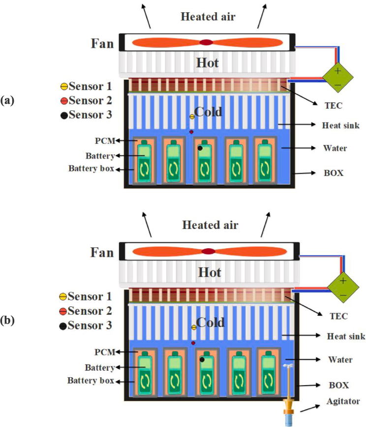
(a) Battery cooling system with natural convection (model 1), (b) Battery cooling system with forced convection (model 2).
Material
Property
Value
PCM (Paraffin)
Latent Heat
180 kJ/kg
Phase Change Temperature
28 °C
Thermal Conductivity
0.2 W/m·K
Heat Sink (Aluminum)
Thermal Conductivity
205 W/m·K
Water
Specific Heat Capacity
4.18 kJ/kg·K
Thermal Conductivity
0.6 W/m·K
Battery Shell (Aluminum)
Thermal Conductivity
205 W/m·K
During its operational state, this system facilitates the transfer of thermal energy generated by the battery to the surrounding water. As the surrounding water temperature of the battery rises, it induces the occurrence of unrestricted fluid motion, leading to the upward movement of the heated fluid into the TEC heatsink. During this particular phase, the thermal energy of the fluid is effectively transferred to the TEC module (natural convection), resulting in a subsequent decrease in its temperature. Subsequently, the cooled fluid is conveyed in a downward direction. The phenomenon of displacement within a fluid can transpire without the requirement of electrical energy consumption.
Similar to the first model, the second model has a similar structure. However, this model has a fundamental distinction. In the first model, the heat from the battery to the TEC was accomplished through the natural convection of the fluid (hot water), whereas in the second model, the fluid is in forced convection. In this novel mode, the fluid inside the batteries is circulated using an electric stirrer. Continuously moving within the battery compartment, this agitator transports fluid to the TEC module. This model's configuration and fluid movement are depicted in Fig. 1-b.
During all experiments, the ambient temperature was maintained at approximately 25 °C. The agitator operated at a power of 5 W and a speed of 1500 RPM, while the fan used for cooling the TEC module operated at a power of 2 W and a speed of 2000 RPM. The constructed model employs TEC1-12709 TEC modules (Rezaei Rad et al., 2023). This module's dimensions are 40 × 40 mm with a thickness of 3.5 mm. This module's maximum cooling capacity is 80 w, and it requires a DC power supply with a voltage of 12 V and a current of 9 amps to produce this cooling.
2.1 Battery model
During these experiments, a cartridge heater is employed as a means to replicate the heat generation mechanism exhibited by the battery. The rationale behind employing this approach lies in the presence of unpredictable variables and the potential for thermal runaway in actual battery systems during testing. The generation of heat can be achieved conveniently and without compromising safety by employing a heater in conjunction with a power supply. In order to replicate the thermal characteristics of the actual battery, a cylindrical aluminum structure is fabricated to match the geometric dimensions of the 18,650 lithium-ion battery. The electric heater is positioned within the aluminum cylinder, precisely at its center, while the region between the heater and the cylinder is filled with silicone paste. The selection of heater power is contingent upon the dimensions and capacity of the battery. The estimation of power is derived from the findings presented in previously published articles (Gadsden et al., 2011; Giuliano et al., 2011). The heater used in the study by Lyu et al. (2019) was the CSH-02120 model, which had a 20 W power rating. The current investigation utilized a heater possessing a maximum power output of 50 w, attainable through the manipulation of its voltage to achieve lower levels of heating power. The battery model is depicted in Fig. 2.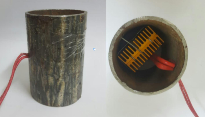
A battery model made instead of a real battery.
3 Experimental process
The battery cooling system was assessed using TEC technology during the experimental testing phase. The trials were classified into two categories: “water under forced convection” and “water under free convection”. Each experiment consisted of three tests with power levels of 10, 30, and 50 W. The duration of each test was 60 min. During each test, the temperature was recorded at four specific locations (battery surface, inside PCM, water, and TEC heating) at regular intervals of 5 min. Fig. 3 depicts the procedure of the experimental test.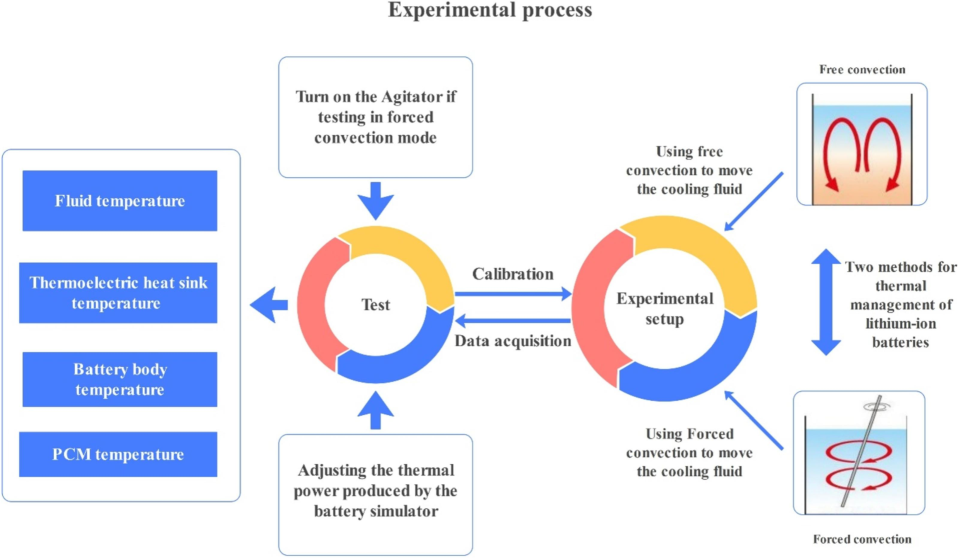
Experimental process flowchart.
3.1 Uncertainties in the Experiment
In any experimental setup, several sources of uncertainty can impact the accuracy and reliability of the results. For this study, the main uncertainties include:
Measurement Uncertainty: The precision of temperature sensors and data logging equipment can introduce errors. Calibration of sensors was performed to minimize these uncertainties, but slight deviations are still possible. The uncertainty in temperature measurements is estimated to be ± 0.2 °C, which corresponds to approximately ± 1 %.
Environmental Variability: Fluctuations in ambient conditions such as room temperature and humidity can affect the thermal performance of the system. Efforts were made to maintain consistent ambient conditions, but minor variations (±1.5 °C in ambient temperature) could not be entirely eliminated. This corresponds to an uncertainty of approximately ± 6 %.
Heat Transfer Assumptions: Assumptions made in the heat transfer models, such as uniform distribution of temperature and ideal contact between components, can also contribute to uncertainty. Real-world conditions may differ from these assumptions, resulting in an estimated uncertainty of ± 2 %.
Combining these uncertainties, the overall uncertainty in the experiment is estimated to be approximately ± 4.67 %, calculated by taking the square root of the sum of the squares of individual uncertainties.
4 Results and Discussion
Prior to investigating the effect of heat transfer between various components, it is necessary to examine the changes in battery temperature over time for different battery power states. Fig. 4 illustrates the changes in battery temperature over time for various battery heat power conditions. According to this graph, which takes into account three types of batteries with heat powers of 10, 30, and 50 w, it can be seen that as the heat power of the batteries increases, the process of attaining independence is delayed. In addition, this graph demonstrates that the battery temperature increases with increasing capacity.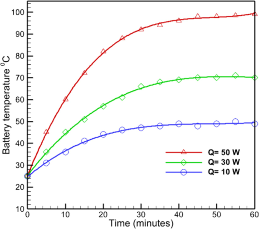
The temperature of the battery body without cooling system.
4.1 Natural convection
Fig. 5-a illustrates the variations in water temperature as a function of time for three battery modes of 10, 30, and 50 w using natural convection heat transfer. It can be seen from this graph that, when a 50-w battery is used, the water temperature hardly fluctuates over time and remains nearly constant. Consequently, it is possible to express the temperature behavior of the water flow independent of time using the natural convection heat transfer for this state. For other circumstances, however, it can be observed that the rate of water temperature decrease increases as battery heat capacity decreases, and for a 10-w battery, this temperature reaches its lowest value, which is consistent with the stated content. For the 30-w battery mode, it can be observed that the current began to decrease at a slower rate than it did for the 10-w battery mode, that this temperature decrease ceased after a while, and that the temperature of the water flow remained constant.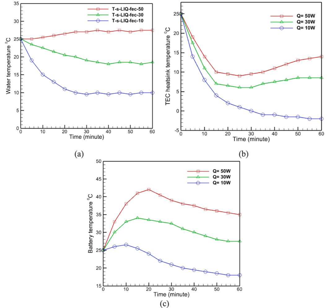
(a)Water temperature inside the battery cooling, (b) Heat sink temperature, (c) Battery temperature.
In the integrated system, the battery generates heat while the TEC produces cooling. Initially, the heat generated by the battery is absorbed by the PCM, stabilizing the temperature due to the phase change. Meanwhile, the cooling effect of the TEC causes the temperature of the water to drop until a thermal balance is achieved between the generated heat and the cooling capacity.
In addition, Fig. 5-b depicts the change in heat sink temperature as a result of heat transfer using the natural convection method for three battery modes. This graph demonstrates that, in the case of a 10-w battery, the heat sink experienced a suitable temperature decrease and a temperature decrease process with a relatively steep slope (relative to other states) due to the lower temperature increase that was initially created for it.
After evaluating the temperature changes of the water flow and heat sink in the presence of batteries with differing heat powers, the natural convection method is used to evaluate the temperature changes of the battery in heat transfer mode. Fig. 5-c is employed for this purpose. It is evident from this graph that the temperature of the battery increases in various conditions. In these modes, the battery temperature begins to rise from the ambient temperature (25 °C) and reaches a maximum of approximately 42 °C in the 50-w battery mode. According to the heat transfer mechanism examined in the problem's physics section, each battery's temperature begins to decrease with the passage of time after attaining its maximum temperature in its various states. According to the slope of the graphs for each of these batteries, it can be seen that as battery power increases, the rate of temperature decreases, with the 10-w battery exhibiting the greatest rate of decrease due to its power-dependent temperature changes. Its output is lower than that of other batteries.
The temperature curve increases after 30 min when the power is 50 W in Fig. 5-b can be attributed to the limitations of the natural convection cooling method. As the power increases, the heat generated by the battery also increases, leading to a higher thermal load on the system. Initially, the natural convection cooling is able to dissipate the heat effectively. However, as the thermal load continues to increase, the cooling efficiency of the system decreases, causing a gradual rise in temperature. This is particularly noticeable in the 50 W power condition, where the system reaches its maximum cooling capacity, and the heat dissipation rate becomes insufficient to counterbalance the heat generation, resulting in an increase in temperature.
4.2 Forced convection
Fig. 6-a depicts the variations in fluid temperature over time as a result of forced convection heat transfer in the presence of batteries with differing thermal powers. Using forced circulation, the water temperature in the 50-w battery mode is observed to be nearly constant at 25 degrees. Furthermore, the water temperature in this instance is independent of time. By observing the temperature variations in this state using natural convection, it was determined that the temperature will reach a maximum of approximately 27 degrees Celsius after approximately 60 min. Consequently, convection reduces the temperature by about 8 % in 60 min. Considering the 5 w of power required to rotate the propeller, it appears that using forced convection to alter the water temperature is not cost-effective. Using forced convection to reduce water fluid temperature for 30-w and 10-w batteries has resulted in a 14 percent and 20 percent increase, respectively, in water fluid temperature reduction. According to the stated issues, it is possible to conclude that the use of forced convection to reduce the temperature of the water fluid in the presence of batteries with lesser power has a more appropriate effect, whereas for batteries with high power, this method does not appear to be appropriate.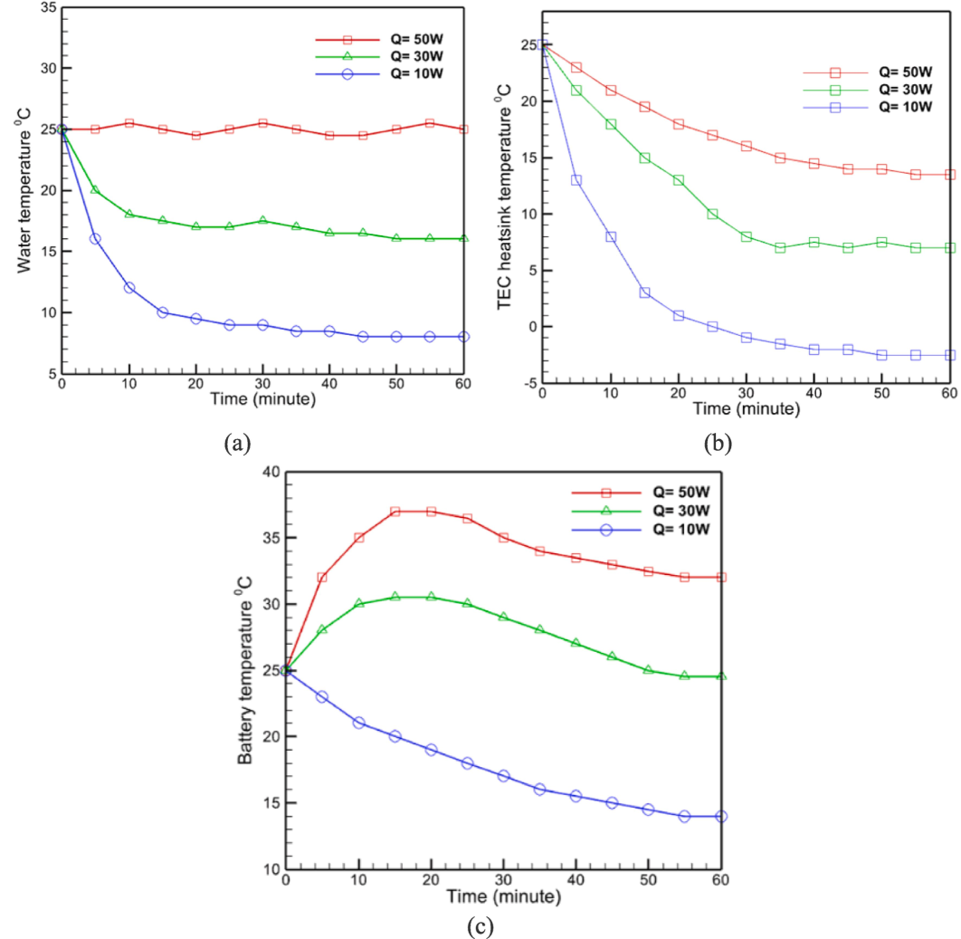
(a) Water temperature inside the battery cooling tank, (b) Heat sink temperature, (c) Battery temperature (Forced convection case).
Using forced convection heat transfer, the temperature variations of the heat sink are analyzed and the effect of this heat transfer method on the temperature reduction of the heat sink is determined. In this case, Fig. 6-b depicts the temperature variations of the heat sink. According to this figure, for the two modes of 50 and 30 w batteries, the increase in temperature that occurred for the battery after a certain amount of time in natural convection mode has been compensated, and the temperature of the heat sink is nearly constant after a certain amount of time. Notable in this case, however, is that the final temperature of the heat sink at the end of the state of reaching a constant temperature for these two battery modes is nearly equal to the maximum temperature specified for them at the end of the 60-minute period when natural convection heat transfer is used for it. In light of the negligible difference between forced convection and natural convection for these two battery modes, the use of forced convection for these two modes can be deemed inappropriate. The same trend is also observed for the 10 W battery mode, and in general, the use of forced convection to reduce the heat sink temperature is inappropriate due to the associated costs and limitations (relative to natural convection) that this method creates.
Fig. 6-c depicts the variations in battery temperature over time for batteries utilizing forced convection heat transfer. After reaching their utmost value, the 30 and 50 w batteries experience a gradual decrease in temperature, reaching 34 and 25 degrees, respectively, after approximately 50 min. The 10-w mode reaches a minimum temperature of approximately 14 degrees. Based on the slope of the temperature change in this graph, it can be seen that, similar to the natural convection heat transfer mode, the 10-w battery mode has a faster rate of temperature decrease.
The temperature curve in Fig. 6-C rises first and then decreases due to the initial heat generation exceeding the cooling capacity of the system. As the experiment starts and power is applied, the battery's temperature rises rapidly because the heat generated exceeds the system's initial heat dissipation capability. Over time, the system becomes more effective at dissipating the heat as it reaches its maximum cooling efficiency, causing the temperature to peak and then gradually decrease as the heat dissipation balances the heat generation.
The heat sink can reach temperatures below 0 degrees Celsius due to the performance of TECs in deep cooling (See Fig. 6-b). TEC create significant temperature differences across their plates. When activated, electricity flows through the TEC, cooling one side significantly while heating the other. The cooled side can reach sub-zero temperatures until thermal equilibrium is achieved between cooling and heating.
4.3 Comparison of natural and forced convection
The greatest temperature for the 50-w battery mode in natural and forced convection is 42 degrees Celsius and 37 degrees Celsius, respectively, indicating a decrease of approximately 12 % for forced convection (Fig. 7). Also, for the 30-w battery mode, these figures are 34 and 31, respectively, indicating a 9 % decrease in maximum temperature in forced convection mode compared to natural convection mode. It is equal to 26 and 23, respectively, for battery mode with 10 w, indicating a 14 % decrease in maximal temperature between forced convection and natural convection. According to the stated content, it can be concluded that the use of forced convection heat transfer method has little effect on reducing the temperature of different parts of the test geometry and reduces the maximum temperature of the batteries under different conditions by no more than 14 %. Due to the need for specialized apparatus and the limitations it imposes, this method of heat transfer is inapplicable, and its implementation will necessitate additional research, which may include technical and economic analyses.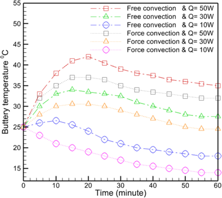
Comparison of natural convection and forced convection methods for battery cooling.
Fig. 8-a illustrates the maximum temperature of the battery body during various experiments. As anticipated, when natural convection is utilized, the battery body temperature is greater than when forced convection is implemented. The primary factor contributing to this phenomenon is that heat transmission occurs with reduced intensity and a lower heat transfer coefficient in natural convection mode. Additionally, it was noted that when the thermal power is elevated, the battery body experiences an increase in temperature. Under ideal conditions, forced convection results in a temperature of 37 degrees Celsius, while natural convection reaches 42 degrees Celsius.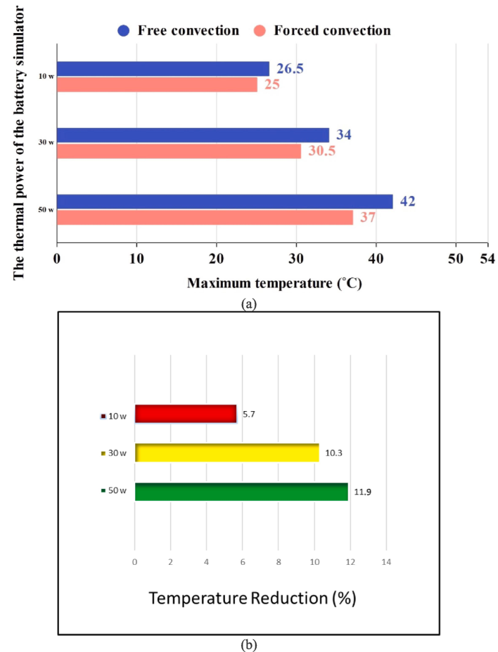
(a) The maximum temperature of the battery body in different tests; (b) Battery temperature reduction percentage when forced convection is used.
The comparison of success rates between forced convection and natural convection is illustrated in Fig. 8-b. Evidently, the implementation of forced convection yielded significant results when operating at 30 and 50 W, decreasing the battery's maximal temperature by 10.3 and 11.9 %, respectively. However, when subjected to a thermal power of 10 W, the intended outcome of reducing the maximal temperature of the battery was only a 5.7 % decrease. The reason for this is that at high power, the heat transfer coefficient increases through the creation of forced convection, which increases the heat transfer rate and consequently affects the temperature of the battery to a greater extent. At lower capacities, natural convection has effectively managed the heat transfer. Therefore, it can be concluded that natural convection is preferable to forced convection for energy conservation, provided that the heat generated by the battery does not surpass a specific threshold.
4.4 Cyclic thermal management capability
Cyclic thermal management capability refers to the ability of a system to effectively manage and regulate temperature fluctuations over time. This involves both heating and cooling mechanisms that respond dynamically to changes in thermal conditions, ensuring optimal performance. In this study, we evaluated the cyclic thermal management capability of the battery thermal management system using a battery simulator to test different heat generation capacities. The system was tested over 20 cycles with varying heat generation capacities to evaluate its performance. Throughout the 20 cycles, the system maintained the simulated battery temperature within the optimal range of 20–40 °C. No significant degradation in cooling efficiency was observed over the 20 cycles, indicating robust thermal management capability.
5 Conclusion
This study assessed the effectiveness of natural and forced convection heat transfer methods in managing battery temperatures. It was found that natural convection consistently led to higher maximum battery temperatures compared to forced convection due to its lower heat transfer coefficient and intensity. Specifically, forced convection reduced the maximum temperature of a 50-watt battery by approximately 12 %, from 42 °C with natural convection to 37 °C. Similar reductions of 9 % and 14 % were observed for 30-watt and 10-watt batteries, respectively.
Forced convection demonstrated varying degrees of success depending on the battery's thermal power. It achieved significant temperature decreases of 10.3 % and 11.9 % for 30-watt and 50-watt batteries, respectively, while only a 5.7 % decrease was noted for the 10-watt battery. This highlights its effectiveness in higher power scenarios and underscores the limitations in lower power applications.
Overall, the findings underscore the critical role of forced convection in enhancing the thermal management of batteries, especially in higher power settings, and emphasize the need for optimized cooling strategies tailored to specific thermal loads.
CRediT authorship contribution statement
Mohammed A. Alghassab: Writing – review & editing, Writing – original draft, Visualization, Validation, Resources, Methodology, Investigation, Formal analysis, Conceptualization.
Acknowledgment
The author would like to thank the Deanship of Scientific Research at Shaqra University for supporting this work.
Declaration of competing interest
The authors declare that they have no known competing financial interests or personal relationships that could have appeared to influence the work reported in this paper.
References
- Configuration, design, and optimization of air-cooled battery thermal management system for electric vehicles: A review. Renew. Sustain. Energy Rev.. 2020;125:109815
- [Google Scholar]
- A new concept of thermal management system in Li-ion battery using air cooling and heat pipe for electric vehicles. Appl. Therm. Eng.. 2020;174:115280
- [Google Scholar]
- Comparisons of different cooling systems for thermal management of lithium-ion battery packs: Phase change material, nano-enhanced channel cooling and hybrid method. J. Storage Mater.. 2024;90:111865
- [Google Scholar]
- Gadsden, S., Al-Shabi, M., & Habibi, S. (2011). Estimation strategies for the condition monitoring of a battery system in a hybrid electric vehicle. International Scholarly Research Notices, 2011.
- A Review of Advanced Cooling Strategies for Battery Thermal Management Systems in Electric Vehicles. Symmetry. 2023;15(7):1322.
- [Google Scholar]
- Thermal analysis and management of lithium–titanate batteries. J. Power Sources. 2011;196(15):6517-6524.
- [Google Scholar]
- Design of a new optimized U-shaped lightweight liquid-cooled battery thermal management system for electric vehicles: A machine learning approach. Int. Commun. Heat Mass Transfer. 2022;136:106209
- [Google Scholar]
- Review on battery thermal management system for electric vehicles. Appl. Therm. Eng.. 2019;149:192-212.
- [Google Scholar]
- Thermal issues about Li-ion batteries and recent progress in battery thermal management systems: A review. Energ. Conver. Manage.. 2017;150:304-330.
- [Google Scholar]
- Electric vehicle battery thermal management system with thermoelectric cooling. Energy Rep.. 2019;5:822-827.
- [Google Scholar]
- Effect of non-conjugate and conjugate condition on heat transfer from battery pack. Alex. Eng. J.. 2022;61(4):3131-3145.
- [Google Scholar]
- Mostafavi, A., & Jain, A. (2020). Modeling and Analysis of a Thermal Management System With Thermoelectric Cooling for the Application in Li-Ion Batteries. ASME Power Conference.
- Design optimization of Air-Cooled Li-ion battery thermal management system with Step-like divergence plenum for electric vehicles. Alex. Eng. J.. 2023;71:631-644.
- [Google Scholar]
- A review of power battery thermal energy management. Renew. Sustain. Energy Rev.. 2011;15(9):4554-4571.
- [Google Scholar]
- An experimental study to evaluate the performance of an HDH water desalination system with a thermoelectric condenser. Renewable Energy Research and 2023 Applications
- [Google Scholar]
- Battery thermal management system for the cooling of Li-Ion batteries, used in electric vehicles. Mater. Today Proc. 2023
- [Google Scholar]
- A review of thermal management methods for electric vehicle batteries based on heat pipes and PCM. J. Braz. Soc. Mech. Sci. Eng.. 2023;45(2):90.
- [Google Scholar]
- Thermal management system based on phase change material (PCM) and heat pipe in Lithium-ion electric vehicle batteries. J. Adv. Res. Experim. Fluid Mech. Heat Transfer. 2021;3(1):26-35.
- [Google Scholar]
- A critical review of thermal management models and solutions of lithium-ion batteries for the development of pure electric vehicles. Renew. Sustain. Energy Rev.. 2016;64:106-128.
- [Google Scholar]
- Novel design optimization for passive cooling PCM assisted battery thermal management system in electric vehicles. Case Stud. Therm. Eng.. 2022;32:101896
- [Google Scholar]
- An up-to-date review on the design improvement and optimization of the liquid-cooling battery thermal management system for electric vehicles. Appl. Therm. Eng.. 2022;119626
- [Google Scholar]


