

Translate this page into:
Validation of a 10 MV photon beam Elekta Synergy linear accelerator using the BEAMnrc MC code
-
Received: ,
Accepted: ,
This article was originally published by Elsevier and was migrated to Scientific Scholar after the change of Publisher.
Peer review under responsibility of King Saud University.
Abstract
Objective: The Monte Carlo (MC) technique can accurately model any linear accelerator where accurate details about the treatment head and the incident electron beam have been provided. However, manufacturers generally do not provide such details as the energy, radial intensity (spot size), or the angular spread of the incident electron beam. The aim of this study is to predict these details and validate a MC Linac model with the measurements.
Methodology: A 10 MV photon beam from an Elekta Synergy Linac was modelled using the BEAMnrc code. The percentage depth dose of the MC model was generated using different electron energies and compared with the measurements using a Gamma index ( ) with two different criteria sets. The dose profiles of the fine-tuned electron energy were generated using different spot sizes and compared with appropriate measurements. In addition, the fine-tuned electron energy and spot size dose profiles were generated using different angular spreads to minimise any differences. Finally, the output factors for different field sizes, with and without a wedge, and also the quality index, were compared.
Results: The fine-tuned electron energy of the MC model was found to be 9.8 MeV, where 94.12% of the calculation points pass the test. For the spot size, a circular radial intensity of 0.35 cm best described the 10 MV photon beam. Furthermore, a mean angular spread of 0.05° minimised the cross-field profile differences between calculation and measurement. The largest differences between the output factors from the MC model and measurements were -0.8% and 4.7% for an open and wedged field, respectively. Ultimately, a difference of 0.82% in the quality index was achieved.
Conclusion: A reliable MC model of a 10 MV photon beam Elekta Synergy Linac can be achieved as presented in this study using the BEAMnrc code. This model can be reliably used to calculate dose distributions.
Keywords
Elekta Synergy Linac
MC validation
Monte Carlo simulation
BEAMnrc

1 Introduction
Monte Carlo (MC) simulations are considered to be amongst the most accurate dose calculation algorithms currently available and are considered to represent the gold standard by which to benchmark other dose calculation algorithms (Chetty et al., 2007; Seco and Verhaegen, 2013). This is due to the fact that MC method takes into account all aspects of electron and photon transport, even in non-homogeneous media. The MC technique is a reliable tool by which to model any linear accelerator (Linac) if its geometry, components and material compositions are known in detail. This Linac information is provided by the manufacturer and may, on occasion, need to be updated or corrected (Chibani and Ma, 2007). An accurate MC model of the Linac improves the accuracy of the dosimetry calculation for radiotherapy treatment planning, reducing dosimetric uncertainty and thus improving patient quality of life.
Many studies have investigated different Linacs using different MC codes for different beam energies. Such codes include BEAMnrc (Rogers et al., 2009), GEANT4 (Agostinelli et al., 2003), MCNP (Forster et al., 2004), FLUKA (Ferrari et al., 2005) and PENELOPE (Salvat et al., 2006). Of these, BEAMnrc is the most widely used for Linac simulation, as it is considered a major improvement in this field (Seco and Verhaegen, 2013). The BEAMnrc MC code has been used to model Varian (Bergman et al., 2014; Mohammed et al., 2018a), Elekta (Almberg et al., 2011; Oderinde and du Plessis, 2016; Gholampourkashi et al., 2018) and Siemens (Joosten et al., 2011; Tuğrul and Eroğul, 2019) Linac. However, the main challenge to any MC model is the determination of the energy, the radial intensity (spot size), and the mean angular spread of the electron beam that produces the bremsstrahlung radiation from the Linac. This is due to the fact that this information is not provided by the manufacturer; it can, however, be predicted by performing trial-and-error procedures.
Sheikh-Bagheri and Rogers (2002) used the BEAM MC code to simulate nine photon beams from different manufacturers and found that the MC models are highly sensitive to the energy and the radial intensity. In addition, Almberg et al. (2011) found that the MC simulations are also sensitive to the mean angular spread when the BEAMnrc MC code was used to model a 6 and a 15 MV photon beam from an Elekta Synergy Linac. The results showed that the best match was achieved when using electron energies of 6.45 and 13.35 MeV, respectively. In addition, the radial intensity distribution was found to be elliptical, at 0.25 mm (in-plane) and 1 mm (cross-plane) with a 0.7 mean angular spread for the 6 MV beam and a 0.5 mm spot size with 0.5 mean angular spread for the 15 MV beam. Gholampourkashi et al. (2018) modelled a 6 MV photon beam from an Elekta Infinity Linac with Agility head and found that the electron energy was 6.6 0.1 MeV and the spot size was 1 mm (in-plane) and 2.1 mm (cross-plane) with a 1.35 mean angular spread. Based on general research observations, the percentage depth dose (PDD) or depth dose matching between the MC model and measurements can determine the electron energy, and dose profiles can determine the spot size and the mean angular spread (Sheikh-Bagheri and Rogers, 2002; Verhaegen and Seuntjens, 2003; Chibani et al., 2010; Almberg et al., 2011; Gholampourkashi et al. 2018; Mohammed et al., 2018b).
This study validates an MC model of a 10 MV photon beam from an Elekta Synergy Linac (with a standard MLCi2 head), which is demonstrated for the first time. Previous work has modelled different energies from the same Linac, or different energies from the same Linac with different heads. The Elekta Linac is modelled using the BEAMnrc MC code and the validation of the model with actual measurements is investigated. Firstly, the PDDs are compared between the MC model and measurements to determine the best match electron energy. The photon dose profiles for the fine-tuned electron energy are then compared with the measurements to determine the spot size, and different angular spreads care considered to minimise the deviations between the MC model and the measurements. Finally, the output factors for different field sizes and the quality index of the fine-tuned model are compared with the measurements.
2 Method and materials
2.1 Linear accelerator
The 10 MV beam from the Elekta Synergy linear accelerator at Singleton Hospital, Swansea, UK (version 4.5, ElektaTM, Crawley, West Sussex, UK) was modelled using the BEAMnrc MC code. The Linac, with a standard MLCi2 head, consists of the target, primary collimator, two flattening filters, chamber, backscatter plate, multi-leaf collimator (MLC), backup jaws, secondary collimator and Mylar sheet, and applicator, as shown in Fig. 1. Using relevant component modules (CMs), each of the head components was built based on manufacturer information, including aspects developed by a previous PhD student (Alsaleh, 2014). The Linac produces two beam energies, 6 MV and 10 MV. If the 10 MV beam is used, the Linac uses an additional steeper flattening filter located within the bore of the primary collimator, thus making it more complicated to accurately simulate.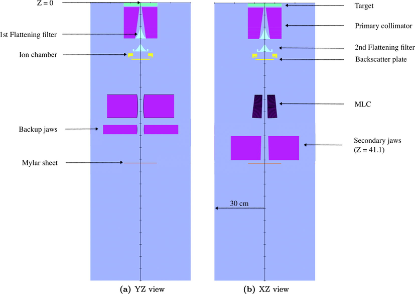
Components of the MC model of the Linac head from two different viewpoints.
The MC Linac model was validated and tuned with the commissioning measurement data. This includes the PDD, dose profiles, output factors and quality index. This measurement was obtained using a water tank (PTW, Freiburg, Germany), with a PTW semiflex ionisation chamber 0.125 cc volume.
2.2 BEAMnrc user code
The BEAMnrc code was used to simulate a 10 10 cm2 field size defined at 100 cm to tune the Linac model (Rogers et al., 2009). The source used in this study was source number 19, an elliptical beam with a gaussian distribution. The field size of the beam field is defined using MLC (cross-plane profile/y-profile), backup jaws (in-plane profile/x-profile) and secondary collimator components.
Most of the simulation parameters used in the BEAMnrc code were left at the recommended (default) values. The energy cutoffs for electrons and photons (ECUT and PCUT) were set to 700 keV and 10 keV, respectively. For all the MC simulations, different variance reduction techniques were used in order to increase the simulation efficiency. These included directional bremsstrahlung splitting (DBS), bremsstrahlung cross-section enhancement (BCSE), and range rejection. The DBS had a splitting number of 10,000 (NBRSPL), and various splitting field radii depending on which field size was used, whilst the source to surface distance (SSD) at which the field was defined was 100 cm. The BCSE was used where 20 and 0 were used for the enhancement constant (BCSE_FACTOR_C) and the enhancement power (BCSE_FACTOR), respectively, and the range rejection for 1 MeV was used.
2.3 DOSXYZnrc user code
A water tank phantom was modelled using the DOSXYZnrc user code (Walters et al., 2005). The phantom size was 21.25 21.25 36 cm with a voxel size of 0.5 0.5 0.5 cm. Source number 9 (BEAM treatment head simulation) was used. Most of the simulation parameters used in the DOSXYZnrc codes were left at their recommended (default) values. To maximize the DOSXYZnrc calculation efficiency, the photon splitting number (n_split) technique was used and set to 35, and fat photons from DBS were excluded. In addition, the PRESTA-I algorithm was used as the boundary crossing algorithm for efficiency reasons. For the same reasons, the Evaluated Photon Data Library (EPDL) cross-section was used to represent the photon cross-section (Zeghari et al., 2019).
2.4 Tuning Linac model
2.4.1 Determination of electron kinetic energy
In order to predict the exact electron energy, the PDD curves of the MC model were investigated using different electron energies, as the PDD curve is mainly affected by the latter. For the PDD comparison, the dose distributions were calculated and plotted along the central axis using different monoenergetic energies, from 9.5 MeV to 10.5 MeV in increments of 0.1 MeV. A constant SSD of 90 cm was set up and PDD curves were generated and normalised to the maximum dose, which is located at a depth of 2.3 cm. In addition, a one-dimensional global Gamma Index (
) was performed (Low et al., 1998). This uses two separate criteria, the dose difference (DD) at a certain point and the distance-to-agreement (DTA) value, to determine the acceptability of the dose calculation. The
index was calculated using Eq. (1):
For this part of the study, the full width half-maximum (FWHM) of the gaussian intensity distributions of the circular beam (spot size) was fixed and set to 0.1 cm in both the X and Y directions. The mean angular spread was set to 0 . This means that the beam was parallel to the Z-axis. Therefore, any observed effect on the PDD curves would be only due to the change in electron energy.
2.4.2 Determination of radial distribution and angular spread
Based on the PDD comparison, the electron energy that best matches the measurements was used with different FWHM (spot size) values, ranging from 0.1 cm to 0.5 cm in increments of 0.05 cm (in both the X- and Y-directions). In this part of the study, the lateral dose profiles for a 10 10 cm2 field size and 90 cm SSD using different spot sizes were compared with the measurements, as dose profiles are mainly affected by the spot size. The test was performed with two acceptance criteria, as in the previous stage, to provide accurate quantitative comparison.
Consequently, the best spot size value that matches the measurements was used with different mean angular spread values, ranging from 0 to 1 in increments of 0.01 to fit or further reduce cross-field profile differences with the measurements. In addition, the test was performed. After finding the best angular spread, the dose profiles at different depths with a constant SSD of 90 cm for a 10 10 cm2 field size with and without a wedge were determined.
2.4.3 Output factor and quality index comparison
Based on the dose profiles and tuning, the spot size and mean angular spread that best matched the measurements were investigated further using data such as output factors and quality index. The output factors (OF) were calculated as the ratio of the maximum dose for a given field size to the maximum dose of a 10 10 cm field size, where the latter was considered the reference. In this comparison, the SSD was constant at 100 cm with different field sizes that include 5, 10, 15 and 20 cm2, with and without a wedge, were used to compare between MC calculations and measurements.
The quality index (QI) was calculated as the ratio of the dose at a 20 cm depth to that at a 10 cm depth with different SSDs but with the same source chamber (or voxel) distance of 100 cm with a 10 10 cm2 field size.
3 Results and discussion
All simulations were performed on MacOS 10.15.5 with a 3.5 GHz Quad-Core Intel Core i5 processor and 24 Gb of RAM. For each simulation, 49 histories were used to reduce the statistical uncertainty to less than 0.5% along the in-field dose. All the simulations were run from the top of the Linac head, with each simulation split into four parallel jobs, distributing the simulation among four different processors, thus reducing the simulation time to approximately 0.86 h.
3.1 Electron kinetic energy
In order to find the optimal electron energy, the PDD curve is the best quantity to investigate as it is mainly affected by the electron energy. Fig. 2 shows the PDD and relative difference curves of different electron energies compared with the measurement. In general, the differences range from −3.15% to 2.67%. Table 1 shows the
test of different energies with two sets of criteria. For the 2%/2 mm set test, all calculation points showed
index values less than 1. For
index values less than 0.5, an electron energy of 9.8 MeV shows 94.12%. In addition, when using the 1%/2 mm set test, the 9.8 MeV electron energy showed that 94.12% and 77.94% of the calculation points resulted in a
value less than 1 and 0.5, respectively. As a result, based on Fig. 2 and Table 1, the best electron energy is 9.8 MeV, which will be used in the following investigation to tune the MC model.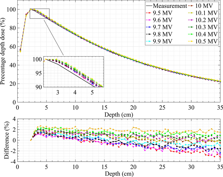
Comparison of PDD curve between measurement and simulation using different electron energies.
2%/2 mm
1%/2 mm
Energy (MeV)
GI
1 (%)
GI
0.5 (%)
GI
1 (%)
GI
0.5 (%)
9.5
100
92.64
92.64
39.71
9.6
100
94.12
94.12
54.41
9.7
100
92.64
92.65
70.59
9.8
100
94.12
94.12
77.94
9.9
100
89.71
89.70
75
10
100
82.35
82.35
63.23
10.1
100
80.88
80.88
63.23
10.2
100
77.94
77.94
55.89
10.3
100
77.94
77.94
50.94
10.4
100
72.05
72.06
47.06
10.5
100
55.88
55.88
23.53
3.2 Radial distribution and angular spread
Based on the results of the previous section, the 9.8 MeV electron beam was investigated with different spot sizes. This radial distribution comparison was made to match the cross-field profiles as well as the penumbra width/shape of the MC model (Almberg et al., 2011). Fig. 3 shows the dose profiles of a 10
10 cm field size at the maximum dose depth using different spot sizes compared with the measurement. As the spot size increased from 0.1 to 0.3 cm, the differences in the dose lateral profiles decreased with a decrease horn at the edges. On increasing the spot size from 0.4 to 0.5 cm, the differences in lateral profiles increased at the edges with a further decreased horn. Table 2 shows the
analysis for different spot sizes using two different sets of acceptance criteria. For the 2%/2 mm set analysis, spot sizes of 0.25 and 0.3 cm showed 97.78%, while 0.35 cm showed 95.56%, with one more point showing a
value of more than 1 in the penumbra region. On the other hand, for the 1%/2 mm set analysis, a 0.35 cm spot size resulted in 93.33% of the calculation (only three points failed, around the penumbra region), where 73.33% of these showed a
value of less than 0.5.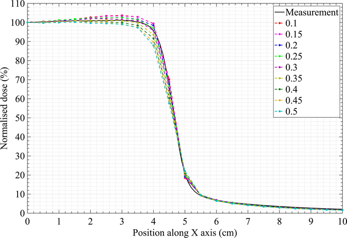
Comparison of dose profiles between measurement and simulation of the 9.8 MeV beam with different spot sizes.
2%/2 mm
1%/2 mm
Spot size (cm)
GI
1 (%)
GI
0.5 (%)
GI
1 (%)
GI
0.5 (%)
0.1
75.56
66.67
66.67
62.22
0.15
75.56
66.67
66.67
57.78
0.2
88.89
68.89
68.89
64.44
0.25
97.78
75.56
75.55
60
0.3
97.78
88.44
84.44
71.11
0.35
95.56
93.33
93.33
73.33
0.4
91.11
62.22
62.22
33.33
0.45
88.89
84.44
84.44
33.33
0.5
84.44
75.56
75.56
24.44
As a result, the FWHM of the gaussian distribution in the X- and Y-directions was chosen to be 0.35 cm for the following stages of the investigation. This circular spot size is similar to that found by Almberg et al. (2011), which was a 0.5 cm circular spot size for a 15 MV beam from the same Linac. The difference between the presented findings and the previous one may be due to the operating beam energy difference.
The dose profiles for the 9.8 MeV electron beam with a 0.35 cm spot size were compared with measurements using angular spreads from the Z-axis ranging from 0
to 1
. This angular spread comparison was made to fit or further minimize cross-field profile differences between the calculation and measurement. Table 3 shows the
index comparison for different mean angular spreads using two different sets of acceptance criteria. From 0.07
to 0.19
, the calculation points that pass the
test decreased gradually, and thus these results are not presented for the sake of brevity, but the general trend holds. It can be clearly seen that the mean angular spread of 0.04
and 0.05
showed the same number of calculation points that pass the
test when using the 2%/2 mm criteria set. On the other hand, the 0.05
resulted in more calculation points that passed the test (at less than 0.5) when using the 1%/2 mm set. As the mean angular spread increased, the percentage of points passing the
test decreased.
2%/2 mm
1%/2 mm
Mean angular spread (deg)
GI
1 (%)
GI
0.5 (%)
GI
1 (%)
GI
0.5 (%)
0.0
95.56
93.33
93.33
73.33
0.01
97.78
93.33
95.56
71.11
0.02
97.78
93.33
95.56
68.89
0.03
97.78
93.33
95.56
64.44
0.04
97.78
95.56
95.56
64.44
0.05
97.78
95.56
95.56
77.78
0.06
95.56
93.33
93.33
68.89
0.07
97.78
93.33
93.33
66.67
1
93.33
75.56
75.56
62.22
As a result, 0.05 appears to be the best mean angular spread, resulting in fewer cross-field profile differences compared with the measurements. Therefore, the MC model of a 10 MV Elekta Synergy Linac achieved the best accuracy when the electron energy was 9.8 MeV, the spot size (FWHM) was 0.35 cm in both directions, and the mean angular spread was 0.05 . These findings are different to those found in previous studies (Almberg et al., 2011; Gholampourkashi et al., 2018), due to differences in the operating beam energy and head used (i.e.. Agility head).
Using the fine-tuned configuration, further comparison was made by plotting dose profiles for a 10
10 cm field size at 2.3, 5, 10 and 20 cm depths with and without a wedge, as shown in Figs. 4 and 5. For an open field, the lowest percentage of calculation points that passed the
test was 91.49% at a 20 cm depth when using the 1%/2 mm set of criteria. For a wedged field, the lowest percentage was 75% at a depth of 10 cm and 95.56% when using the 1%/2 mm and 2%/2 mm sets of criteria, respectively.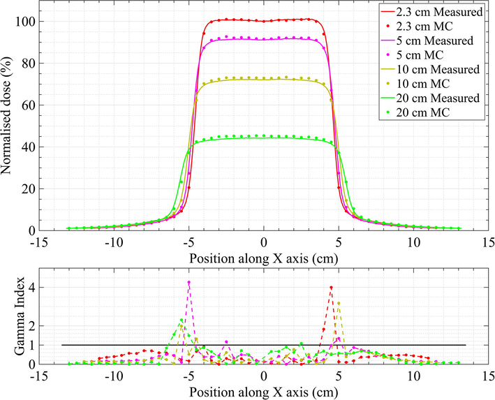
Comparison of dose profiles for the tuned MC model and measurements at different depths with
analysis using the 1%/2 mm set.
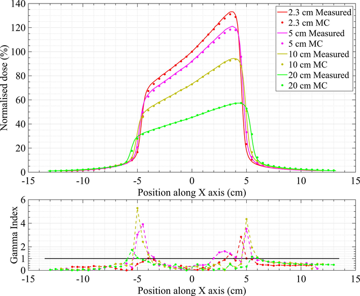
Comparison of dose profiles with a wedge between the tuned MC model and measurements at different depths with
analysis using the 1%/2 mm set.
3.3 Output factor and quality index
Based on the previous results, the best-tuned MC model or configuration that matches the measurements was further investigated using output factors for different field sizes, as shown in Table 4. For the open fields, the largest difference was −0.8% for the 5
5 cm field size. On the other hand, for the wedged fields, the largest difference was found for the 20
20 cm field size, which was 4.7%.
MC
Measurement
Field size (cm)
Open
Wedge
Open
Wedge
5
0.934
0.272
0.941
0.265
10
1
0.301
1
0.289
15
1.0327
0.319
1.033
0.306
20
1.0543
0.333
1.053
0.318
Finally, the quality index was compared between the MC model and the measurements. The QI value of the measurement for a 10 10 cm field size was 0.733, while the QI value of the MC model was 0.739 with a 0.82% difference. Thus the MC model achieved high accuracy. It is worth mentioning that the QI quantity is relatively insensitive to small energy changes, but it is independent of the electron contamination (Kosunen and Rogers, 1993; Day and Aird, 1996).
4 Conclusion
This study has demonstrated the modelling and validation of an MC model of a 10 MV photon beam from an Elekta Synergy Linac head using the BEAMnrc MC code. The fine-tuned model was achieved by setting the energy, radial intensity (spot size), and mean angular spread of electron beam to 9.8 MeV, 0.35 cm, and 0.05 , respectively. For dose profiles, the fine-tuned configuration resulted in 95.56% of the calculation points passing the test using a 1%/2 mm acceptance criteria set. In addition, the largest differences between the output factors for the MC model and the measurements were −0.8% and 4.7% for the open and wedged fields, respectively. The quality index difference was only 0.82%. Therefore, the MC model presented in this study can be considered a reliable tool for dose calculations. Finally, the model, and indeed the validation procedure presented, can be used to model different Linacs with different energies taking into account the differences between them.
Acknowledgment
The author gratefully acknowledges the help from staff of the Department of Medical Physics and Clinical Engineering, SBU HB (Swansea Bay University Health Board) for their assistance in this study.
Declaration of Competing Interest
The authors declare that they have no known competing financial interests or personal relationships that could have appeared to influence the work reported in this paper.
References
- Geant4-a simulation toolkit. Nuclear Instruments and Methods in Physics Research Section A: Accelerators, Spectrometers, Detectors and Associated Equipment. 2003;506:250-303.
- [CrossRef] [Google Scholar]
- Monte Carlo linear accelerator simulation of megavoltage photon beams: Independent determination of initial beam parameters. Med. Phys.. 2011;39:40-47.
- [CrossRef] [Google Scholar]
- The prediction of secondary cancer risk after high-energy X- ray radiotherapy using the Monte Carlo method and voxel phantoms. Swansea University; 2014. PhD Thesis
- Monte Carlo modeling of HD120 multileaf collimator on Varian TrueBeam linear accelerator for verification of 6X and 6X FFF VMAT SABR treatment plans. J. Appl. Clin. Med. Phys.. 2014;15:148-163.
- [CrossRef] [Google Scholar]
- Report of the AAPM Task Group No. 105: Issues associated with clinical implementation of Monte Carlo-based photon and electron external beam treatment planning. Med. Phys.. 2007;34:4818-4853.
- [CrossRef] [Google Scholar]
- On the discrepancies between Monte Carlo dose calculations and measurements for the 18MV Varian photon beam. Med. Phys.. 2007;34:1206-1216.
- [CrossRef] [Google Scholar]
- On Monte Carlo modeling of megavoltage photon beams: A revisited study on the sensitivity of beam parameters. Med. Phys.. 2010;38:188-201.
- [CrossRef] [Google Scholar]
- Central axis depth dose data for use in radiotherapy. Br. J. Radiol. Suppl.. 1996;25 84–51
- [Google Scholar]
- FLUKA: A Multi-Particle Transport Code. In: Office of Scientific and Technical Information (OSTI). 2005.
- [Google Scholar]
- MCNPVersion 5. Nuclear Instruments and Methods in Physics Research Section B: Beam Interactions with Materials and Atoms. 2004;213:82-86.
- [CrossRef] [Google Scholar]
- Monte Carlo and analytic modeling of an Elekta Infinity linac with Agility MLC: Investigating the significance of accurate model parameters for small radiation fields. J. Appl. Clin. Med. Phys.. 2018;20:55-67.
- [CrossRef] [Google Scholar]
- Challenges in calculation of the gamma index in radiotherapy - Towards good practice. Phys. Med.. 2017;36:1-11. https://doi.org/1-0.1016/j.ejmp.2017.03.001
- [Google Scholar]
- Variability of a peripheral dose among various linac geometries for second cancer risk assessment. Phys. Med. Biol.. 2011;56:5131-5151.
- [CrossRef] [Google Scholar]
- Beam quality specification for photon beam dosimetry. Med. Phys.. 1993;20:1181-1188.
- [CrossRef] [Google Scholar]
- A technique for the quantitative evaluation of dose distributions. Med. Phys.. 1998;25:656-661.
- [CrossRef] [Google Scholar]
- Monte Carlo simulation of Varian Linac for 6 MV photon beam with BEAMnrc code. Radiat. Phys. Chem.. 2018;144:69-75.
- [CrossRef] [Google Scholar]
- Validation of BEAMnrc Monte Carlo model for a 12 MV photon beam. J. King Saud Univ. Sci.. 2018;30:537-543.
- [CrossRef] [Google Scholar]
- O3. Accurate Monte Carlo modelling of an Elekta Synergy equipped with an Agility 160-Leaf MLC. Phys. Med.. 2016;32:141-142.
- [CrossRef] [Google Scholar]
- BEAMnrc users manual. PIRS: NRC Rep; 2009. p. :509.
- Salvat, F., Fernández-Varea, J.M., Sempau, J. 2006. PENELOPE - a code system for Monte Carlo simulation of electron and photon transport.
- Monte Carlo Techniques in Radiation Therapy. CRC Press; 2013.
- Monte Carlo calculation of nine megavoltage photon beam spectra using the BEAM code. Med. Phys.. 2002;29:391-402.
- [CrossRef] [Google Scholar]
- Determination of initial electron parameters by means of Monte Carlo simulations for the Siemens Artiste Linac 6 MV photon beam. Rep. Pract. Oncol. Radiother.. 2019;24:331-337.
- [CrossRef] [Google Scholar]
- Monte Carlo modelling of external radiotherapy photon beams. Phys. Med. Biol.. 2003;48:R107-R164.
- [CrossRef] [Google Scholar]
- DOSXYZnrc users manual. PIRS: NRC Rep; 2005. p. :794.
- Investigation of variance reduction techniques parameters to enhance the efficiency for a 12 MV photon beam. J. Radiat. Res. Appl. Sci.. 2019;12:192-199.
- [CrossRef] [Google Scholar]


