

Translate this page into:
Use of geoelectrical resistivity method for detecting near-surface groundwater potential zones at Riyadh city, Saudi Arabia
⁎Corresponding author. sadam.ali1191@gmail.com (Saddam Ali Hazaea)
-
Received: ,
Accepted: ,
This article was originally published by Elsevier and was migrated to Scientific Scholar after the change of Publisher.
Peer review under responsibility of King Saud University.
Abstract
Six profiles of the two-dimensional multi-channel electrical resistivity tomography (ERT) were conducted at the northwest part of Riyadh city using the SYSCAL Pro system with a dipole–dipole configuration to detect the near-surface water-bearing potential zones. The ERT field measurements use a series of regularly placed electrodes to measure the electrical resistivity along the profile. The results of the inverse models are displayed as cross-sections of the true resistivity distribution of the subsurface with depth along with each profile. The two-dimensional (2-D) inversion results of the electrical resistivity data indicate three geoelectric zones; 1st zone of low resistivity values (<100 Ω.m), representing two groundwater-bearing potential zones from top to bottom as follows; the 1st one extends downwards to 10- and 15-meters depth, while the 2nd zone spreads between 15- and 30-meters depth, 2nd zone with resistivities ranging from 100 to 1000 Ω.m, which represent the highly fractures limestone; the 3rd zone with resistivities greater than 1000 Ω.m reflecting compacted limestone rocks. It is noticed also some of the low resistivity pockets are isolated through the subsurface geoelectrical cross-section indicating the presence of voids and/or cavities. Based on these results, the investigated area is considered as one of the promising zones for groundwater supply in Riyadh city and its future urbanization expansion projects. This can be accessed by drilling wells down to a depth of 50 m for groundwater extraction.
Keywords
Potential zones
Electrical resistivity
2D inversion
Groundwater
Riyadh
Saudi Arabia

1 Introduction
The Kingdom of Saudi Arabia is one of the arid regions. A thorough understanding of the groundwater resources is therefore important in order to ensure the supply of water, both for residents’ living purposes and for agricultural activities. Indeed, the continued urban expansion of the city of Riyadh, especially its northern part, and the development needs arising from Saudi Arabia’s 2030 Vision, reinforce the need for a comprehensive survey of the water-bearing layers in this area. Accordingly, the aim of this study is to detect near-surface water-bearing zones in the northwest of the city of Riyadh.
The elevation of the study area is below 550 m in the third industrial zone and Al-Kharj road areas and reaches its maximum of 1000 m to the west. The general slope of the area points southeast. The climate is characterized by constant hot prevailing winds with low precipitation. Summer air temperatures reach 45–50 °C. A daily variation of 15 °C in temperature is not uncommon. Temperatures in winter average 20 °C, but can drop to below 5 °C. These climatic conditions promote evaporation, and indeed the evaporation precipitation ratio for the region is 1:30 (Dakhil and Al Gahtani, 1982). Most years are very dry but rainfall occurs at intervals of 7–10 years with high intensity over very short periods, creating flash floods and resulting in high salt concentrations at the end of the horizontal flow, together with significant erosion of soil.
While the population of the city was 40,000 in 1935 and 83,000 in 1949 (Elsheshtawy, 2008), it is now over 7 million. Unexpected and dynamic population growth took place between 1976 and 1990, associated with the economic boom resulting from rising oil prices. Government expenditure increased sharply during this period, and urban development was very rapid, despite planning policies aimed at reducing the unplanned growth and urban dispersal of the city. By 2011, the developed land in the city reached 1219 square kilometers, and this is expected to expand further to 2500 square kilometers by 2030.
The study area is located in the northwestern part of the city of Riyadh, along King Khaled Road, Al-Imam Mohamed Ibn Saud Road, and the Western Ring Road. The exact geographic location is shown in Google satellite imagery (Fig. 1). Along with its western limits, the area is typically bordered by Wadi Hanifah with its complex system of tributaries. It has groundwater potential due to the rainwater which percolates down the valley beds during occasional rainfalls (Zaidi and Kassem, 2012). The study conducted here aimed to reveal the groundwater potential zones in the investigated area, especially near-surface, which are used for drinking or agricultural purposes, considering that this region is occupied with farms, natural parks, and residential communities a high demand for sustainable groundwater supplies.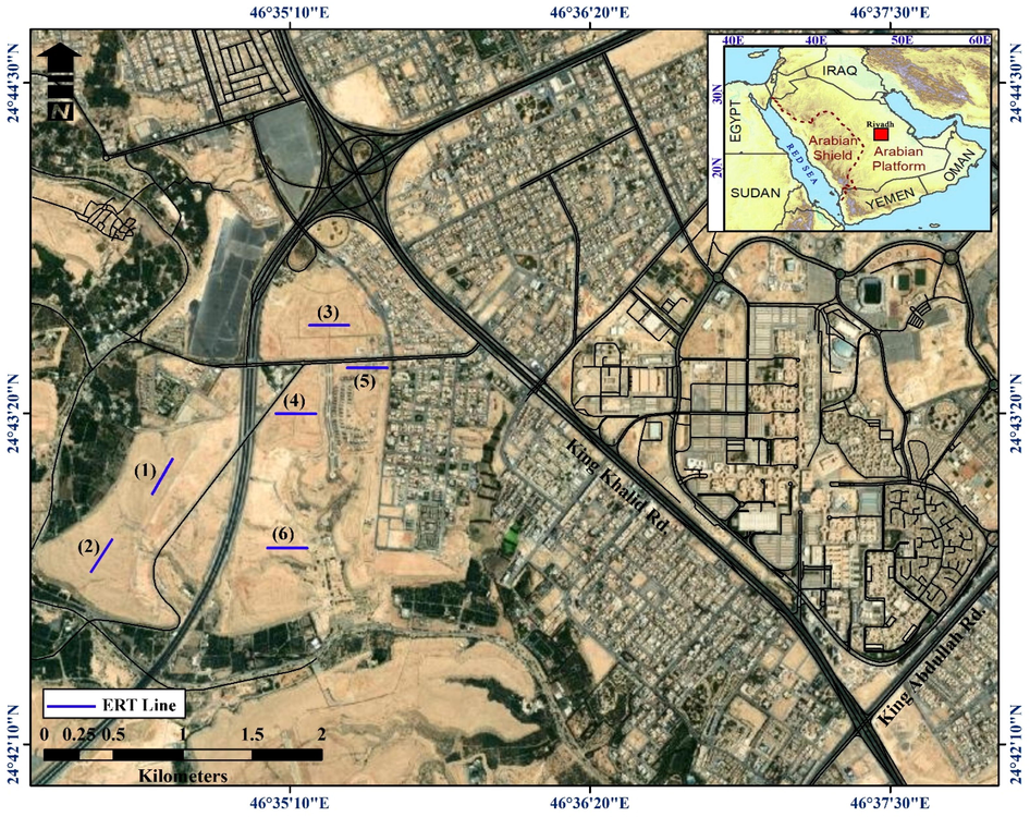
Location map of the study area including the surveyed profiles.
Geoelectrical resistivity investigations are widely used for groundwater exploration (Pellerin, 2002; Yadav and Singh, 2007; Wahab et al., 2021) in arid regions, based on the resistivity contrasts between the different layers (Sasaki, 1992; Store et al., 2000; Naudet et al., 2008; Zaidi and Kassem, 2012; Rai et al., 2013; Sikah et al., 2016; Chen et al., 2018; Dastanboo et al., 2020).
2 Geological setting of the study area
Wadi Hanifah is one of the longest and most important valleys near Riyadh. It is a unique natural geographical feature in the dry region of Najd in central Saudi Arabia. The valley, which is fed by a number of tributaries, is a natural water drainage course for an area of over 4000 square kilometers. It passes through the western edges of Riyadh in its middle part, running from the northwest to the southeast (Fig. 2). The water resources in that valley consist of both continuous watercourses resulting from the daily discharge of 650,000 cubic meters of treated and untreated water. This continuous flow of water results in the presence of lush areas in the otherwise arid landscape. Unfortunately, until recently, segments of Wadi Hanifah, especially those bordering Riyadh, were exploited in an aggressive and environmentally destructive manner. Parts of the valley were used as dumping grounds for rubbish; other parts were quarried for stone or sand. Consequently, a substantial part of the valley has been scarred and polluted and segments of its topography have been extensively modified. In some localities these topographical changes have obstructed the water flow, creating stagnant pools that exhibit swamp-like characteristics.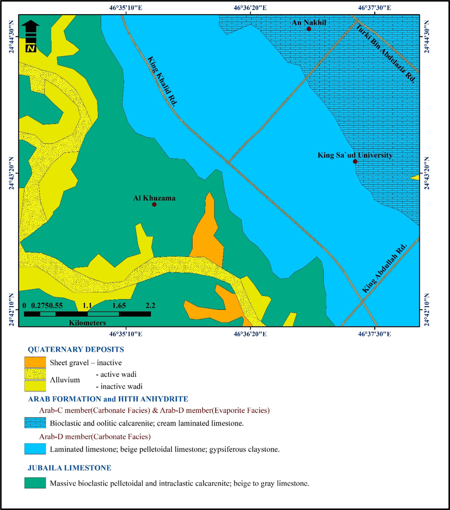
Geologic map of the study area (modified after Vaslet et al., 1991).
Jurassic to Early Cretaceous rocks cropping out in the Riyadh area (Vaslet et al., 1991). The type locality of Hanifa Formation (Early Kimmeridgian) lies in Wadi Hanifa. The subsurface geologic information is based on the geotechnical reports about four boreholes that were drilled to depths varying from 6 to 15 m below the existing ground surface. The subsurface geologic setting at the site consists of three layers that extend from the ground surface to the maximum depths investigated:
-
-
Silty sand with gravel: A top layer of brown medium dense and dry to damp silty sand with gravel. This layer has an average thickness of ∼5.5 m.
-
-
Completely weathered limestone: Below the top layer of the very dense sand; dry to damp and creamy; completely weathered limestone in four boreholes. The thickness of this layer varies from 2.5 to 13.5 m.
-
-
Slightly fractured limestone: Below the top layer of the very dense sand; dry to damp and creamy; slightly fractured limestone in four boreholes.
-
-
Alluvial sediments are well presented in the numerous Wadi channels to the west of Wadi Hanifah that dissect the Jubaila Formation (Vaslet et al., 1991a,b).
3 Hydrogeological setting of the study area
Edgell (1997) showed that the groundwater of Wadi Hanifah is recharged from local rainfall. Potable water is mainly sourced from deep aquifers, whereas water for irrigation and industrial purposes is pumped from shallow aquifers. Fig. 3 shows the variation in water levels in the city of Riyadh. April is the wettest month while September is the driest month. The average amount of annual precipitation is 105.0 mm (4.13 in). The rate of decline in the water level was taken as a measure of the average infiltration rate in the reservoir only when there was a continuous water level decline trend, excluding the rapid decline due to the opening of the gates for controlling the drainage outlet works (Presidency of Meteorology and Environment, 2011 and Ministry of Environment, Water and Agriculture, 2008).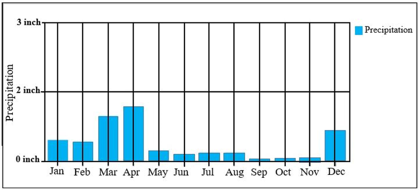
Annual average of rainfall in Riyadh.
4 Methodology
2D electrical resistivity tomography is now mainly carried out with a multi-electrode resistivity meter system. Such surveys use a number of electrodes laid out in a straight line with a constant spacing. A computer-controlled system is then used automatically to select the active electrodes for each measure (Griffiths and Barker, 1993; Dahlin, 1996). The maximum depth penetration within ERT investigations is limited largely by the length of the array. The apparent electrical resistivity distribution of the subsurface is measured using a combination of four electrodes. By injecting a DC, or very low-frequency AC, between a pair of electrodes and measuring the resulting electrical potential difference with the second pair of electrodes, it is possible to calculate the apparent resistivity using a derivation of Ohm’s Law.
Electrical methods include many techniques and configurations (arrays), can be used in areas with noise such as our study area, and are the most commonly used techniques for hydrogeological investigations. In this study and during 6 and 7 February 2016, the ERT data were collected with Dipole-Dipole configuration using Syscal Pro (Iris instruments) system Earth resistivity-meter coupled with a multielectrode system. The electrode spacing was adopted at 2.5 and 3 m, with 48 electrodes along six profiles (Fig. 1). These profiles are configured to cover the selected area and to get the best resolution (Bernard et al., 2006).
5 Data analysis, results, and interpretations
Recorded ERT data are row data with uncorrected apparent resistivity values. This is because the recorded values are a function of all parts of the subsurface that the current has traveled through between electrodes. Conversion of the apparent resistivity to true resistivity is performed via a numerical inversion or regression process, which generates a model with a similar theoretical apparent resistivity distribution to that of the field data. The first stage in producing an electrical image is the construction of a pseudo-section. Each pseudo-section is a visual representation of unprocessed apparent resistivity values. It is useful to compare an inverted cross-section with the raw data to evaluate anomalies observed in the inversion. Fig. 4 shows an example of a pseudo-section where the pseudo-section contains two parts; the upper part is the measured pseudo-section, and the middle part is the calculated pseudo-section while the lower part is the interpreted section.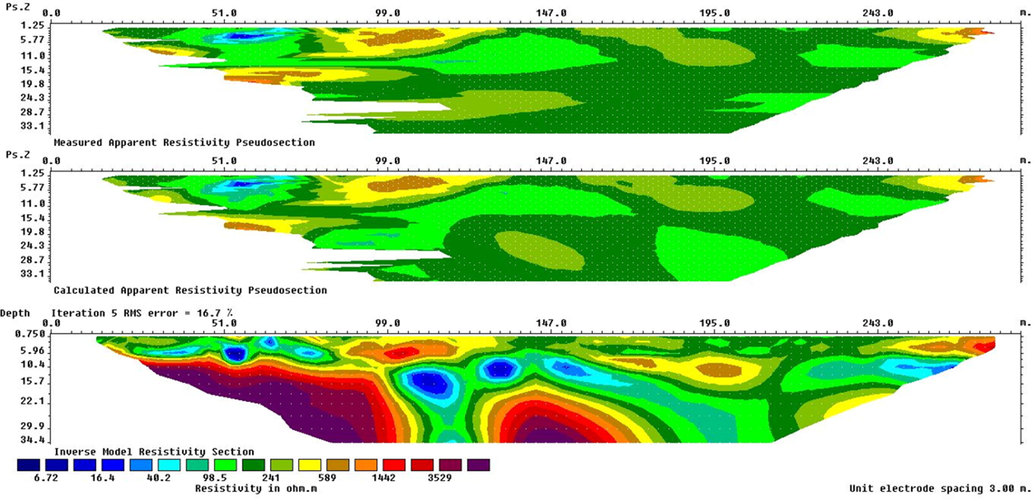
Example of the measured, calculated, and interpreted ERT cross-section.
The RES2DINV resistivity inversion software (Loke, 2002) was used to in this study invert the apparent resistivity data automatically. The least-square fitting technique (Loke and Barker, 1996) was used to get the best fit for the resistivity model by iterations. In all cases, the number of iterations was three with RMS errors ≤5%. The results of the inverse models are displayed as cross-sections of the true resistivity distribution of the subsurface with depth along with each profile. The models show a range of both low resistivity and relatively high resistivity zones.
The inverse model resistivity cross-section for profile no. 1 (Fig. 5) displays localities of low resistivity (<100 Ω.m) at depths starting from 5 m below the earth's surface and extending to depths of 22 m. These low resistivity zones are intruded by high resistivity (>1000 Ω.m) in the central part of the profile with relatively strong lateral and vertical gradients. The northeastern part displays isolated low resistivity anomalies while at different depths appear to be connected to form a dipping water-bearing zone. The southwestern part of the profile reveals low resistivities (<100 Ω.m) extends about 40 m laterally and downward to a depth of 10 to 20 m. On the basis of geological data, low electrical resistivity values (from 50 to 500 Ω⋅m) can be associated with groundwater-bearing zones, moderate resistivities (from 500 Ω⋅m to 1000 Ω⋅m) reflect completely weathered limestone, while high electrical resistivity values (>1000 Ω⋅m) related to compacted limestone bedrock (Boncio et al., 2011).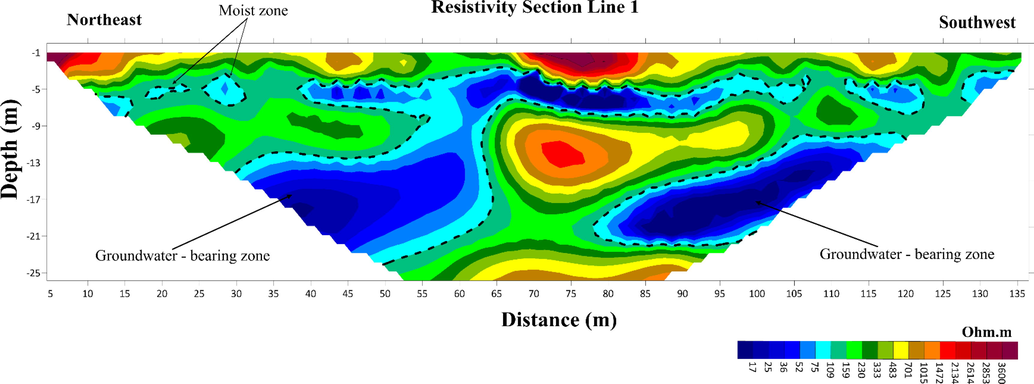
The inverted ERT geoelectric cross-section from profile No.1.
Profile No. 2 (Fig. 6) shows pockets of low resistivities distributed throughout the near-surface depth of about 9 m, the largest one located at the middle part of the profile and extends about 20 m laterally (from 55 to 75 m from the starting point of the profile) with 4 m thick. The main potential zone is characterized by low resistivity (<100 Ω.m) appears at a depth of 20 m and extends to approximately 50 m horizontally (from 55 to 105 m). The third profile (Fig. 7) displays a limited pocket of low resistivity (<110 Ω.m) distributed all over the entire profile. While the main potential zone covers the central part of this profile. These start at a depth of 10 m and extends to 33 m below the surface of the earth. These zones differ in terms of shape, depth, and connection, including circular, oval, and triangular forms. In this profile, the sites of high resistivity separate the zones of low resistivity, thereby preventing them from being connected.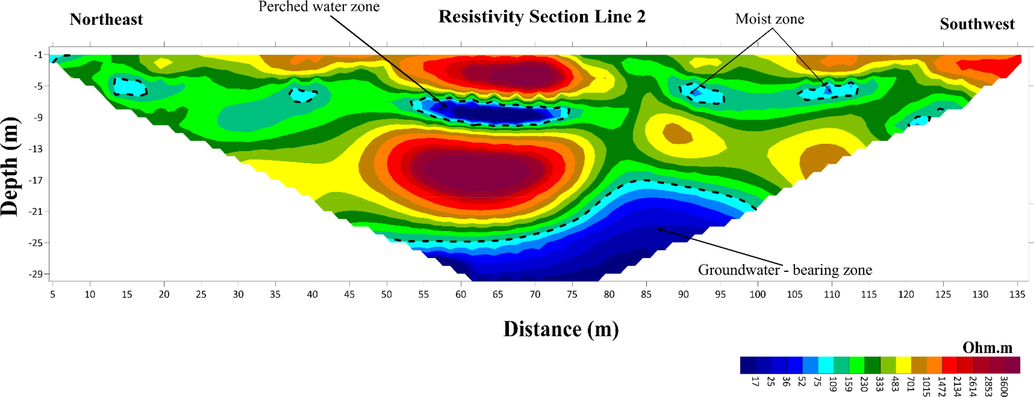
The inverted ERT geoelectric cross-section from profile No.2.
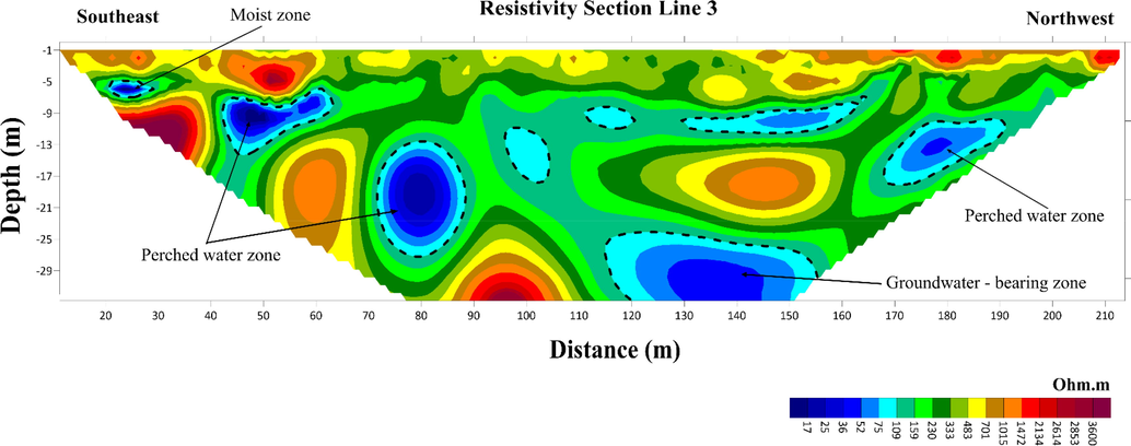
The inverted ERT geoelectric cross-section from profile No.3.
In the fourth profile (Fig. 8), the locations of low resistivity (<110 Ω.m) appear in a dense pattern but at different depths and with varying dimensions. It is noted that, in the eastern part, the zones of low resistivity extend to a depth of 10 m. In the central part, these zones of low resistivity appear at a depth of 10 m and extend down to a depth of 33 m on both sides of a region of high resistivity (>1000 Ω.m). In the western part, the zones of low resistivities appear at the ground surface and extend to 10 m overlaying compacted limestone.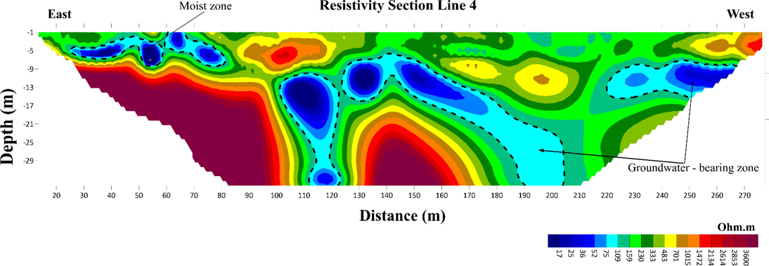
The inverted ERT geoelectric cross-section from profile No.4.
Profile No. 5 (Fig. 9) illustrates a large change in the geoelectric resistivity value, ranging from 10 to 3600 Ω.m. The low resistivity sites (<110 Ω.m) extend with different forms, but they connect with each other to form watercourses underneath the ground surface, especially in the western and eastern parts of the profile. This, therefore, indicates a significant change in the lithological characteristics of the groundwater-bearing zones. As for the central part, the water-bearing horizons appear at two levels: the first level starts at a depth of about 15 m and extends to 25 m in-depth, but has a limited lateral extension; while the other level starts at a depth of 30 m and extends downwards. The eastern part of the profile shows areas of low electrical resistivity at a depth of 5 m, extending down to 13 m, and about 30 m laterally. In addition, some separate locations are detected at different depths. This apparent change in the geoelectric resistivity along with the profile, either vertically or horizontally, indicates that the water-bearing zones are governed by the nature and quality of the limestone rocks carrying water in the area.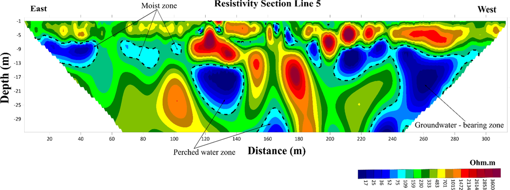
The inverted ERT geoelectric cross-section from profile No.5.
Profile No. 6 (Fig. 10) demonstrates the most significant source of water in the study area, with areas of low electrical resistivities appearing in a continuous channel, extended horizontally and vertically. This promises the existence of large quantities of groundwater in the area in two horizons; surface one extends down to 15 m depth. While the 2nd zone appears at a depth of 30 m with an aerial expansion of 50 m. In this profile, the areas of high geoelectric resistivity (greater than 120 Ω.m) overlap so as to separate the two groundwater sources (<120 Ω.m). The high values appear at a depth of 10 m and extend down to 20 or 30 m (in the northwestern part).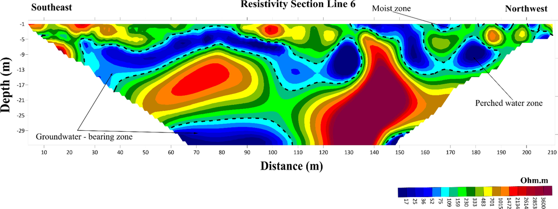
The inverted ERT geoelectric cross-section from profile No.6.
6 Conclusions
Two-dimensional electrical resistivity tomography profiles provided a clear view of subsurface lithological heterogeneities and geological structures (cavities, fractured zones, and compacted rocks) favorable for groundwater potential in the study area. The resulting models illustrate a wide range of both low resistivity and relatively high resistivity zones. The interpretation of the inverted sections of the ERT profiles clarified two water-bearing horizons. The first horizon starts from the ground surface and extended downward to a depth of 10–15 m, while the second one starts from 15 m, although sometimes from 10 m, and continues down to a depth greater than 30 m. The study also identified a number of small discrete pockets, probably voids and/or cavities, spread over the study area.
These results are important for future groundwater exploration in the study area and can help in localizing drilling water wells in this area. Understanding the lateral extent of the shallow groundwater aquifer and the depth to the water-saturated zone (aquifer) will minimize the costs and time required for drilling. Such investigations are recommended for any hydrogeological characterization studies.
Acknowledgements
This research was supported by Researchers Supporting Project number (RSP2022R425), King Saud University, Riyadh, Saudi Arabia.
Declaration of Competing Interest
The authors declare that they have no known competing financial interests or personal relationships that could have appeared to influence the work reported in this paper.
References
- Bernard J, Orlando Leite, Fabrice Vermeersch, 2006. Multi-electrode resistivity imaging for environmental and mining applications. http://www.iris-instrument.com.
- Boncio P., A. Pizzi, G. Cavuoto, M. Mancini, T. Piacentini, E. Miccadei, G.P. Cavinato, S. Piscitelli, A. Giocoli, G. Ferretti, R. De ferrari, M.R. Gallipoli, M. Mucciarelli, V. DI Fiore, A. Franceschini, F. Pergalani, G. Naso and Working Group Macroarea, 2011. Geological and geophysical characterization of the Paganica - San Gregorio area after the April 6, 2009 L’Aquila earthquake (Mw 6.3, central Italy): implications for site response. Bollettino di Geofisica Teorica ed Applicata Vol. 52, n. 3, pp. 491-512. DOI 10.4430/bgta0014.
- Evaluating the application of electrical resistivity tomography for investigating seawater intrusion. Electronics. 2018;7(7):107.
- [Google Scholar]
- 2D resistivity surveying for environmental and engineering applications. First Break. 1996;14:275-283.
- [Google Scholar]
- The deterioration of concrete structures in the environment of Eastern of Saudi Arabia. Arabia J. Sci. Eng.. 1982;7(3):191-209.
- [Google Scholar]
- Comparison between electrical resistivity tomography and tunnel seismic prediction 303 methods for detecting the water zone ahead of the tunnel face: A case study. Open Geosci.. 2020;12:1094-1104.
- [Google Scholar]
- Aquifers of Saudi Arabia and their geological framework. Arab. J. Sci. Eng.. 1997;22:5-31.
- [Google Scholar]
- The evolving Arab City: tradition, modernity and urban development. Routledge; 2008.
- Two-dimensional resistivity imaging and modelling in areas of complex geology. J. Appl. Geophys.. 1993;29(3-4):211-226.
- [Google Scholar]
- Rapid least-squares inversion of apparent resistivity pseudo-sections by a quasi-newton method. Geophys. Prospect.. 1996;44:131-152.
- [Google Scholar]
- Loke, M.H., 2002. RES2DINV, Ver. 3.50, Rapid 2-D resistivity and IP inversion using the least square method.
- Integrated geophysical and geomorphological approach to investigate the snowmelt-triggered landslide of Bosco Piccolo village (Basilicata, southern Italy) Eng. Geol.. 2008;98(3-4):156-167.
- [Google Scholar]
- Applications of electrical and electromagnetic methods for environmental and geotechnical investigations. Surv. Geophys.. 2002;23:101-132.
- [Google Scholar]
- Electrical resistivity tomography for groundwater exploration in a granitic terrain in NGRI campus. Curr. Sci.. 2013;105(10):1410-1418.
- [Google Scholar]
- Resolution of resistivity tomography inferred fromnumerical simulation. Geophys. Prospect.. 1992;40:453-464.
- [Google Scholar]
- Sikah, J.N., Acheampong, A., Aning Sylvester; Danuor K.; Evans M. Collins O., 2016. Groundwater Exploration using 1D and 2D Electrical Resistivity Methods. J. Environ. Earth Sci. 6 (7) 55–63.
- Electrical resistivity tomography to investigate geological structures of earth’s upper crust. Geophys. Prospect.. 2000;48:455-471.
- [Google Scholar]
- Explanatory notes to the geologic map of the Ar Riyad Quadrangle. Sheet 24 I, Kingdom of Saudi Arabia. Ministry of Petroleum and Mineral Resources Jeddah 1991
- [Google Scholar]
- Vaslet D, Al-Muallem MS, Maddah SS, Brosse JM, Fourniguet J, Breton JP, Le Nindre YM, 1991a. Geologic map of the Ar Riyadh quadrangle, sheet 24 I, Kingdom of Saudi Arabia. Saudi Arabian Deputy Ministry for Mineral Resources Geoscience Map GM-121, 54 pp, scale 1:250,000.
- Groundwater aquifer detection using the electrical resistivity method at Ito Campus, Kyushu University (Fukuoka, Japan) Geosci. Lett.. 2021;8(1)
- [Google Scholar]
- Integrated resistivity surveys for delineation of fractures for ground water exploration in hardrock area. J. Appl. Geophys.. 2007;62(3):301-312.
- [Google Scholar]
- Use of electrical resistivity tomography in delineating. Arabian J. Geosci.. 2012;5(2):327-333.
- [Google Scholar]


