

Translate this page into:
State of the art of medical devices featuring smart electro-rheological and magneto-rheological fluids
⁎Corresponding author. seungbok@inha.ac.kr (Seung-Bok Choi) http://www.ssslab.com (Seung-Bok Choi)
-
Received: ,
Accepted: ,
This article was originally published by Elsevier and was migrated to Scientific Scholar after the change of Publisher.
Peer review under responsibility of King Saud University.
Abstract
Recently, smart fluids have drawn significant attention and growing a great interest in a broad range of engineering applications such as automotive and medical areas. In this article, two smart fluids called electro-rheological (ER) fluid and magneto-rheological (MR) fluid are reviewed in terms of medical applications. Especially, this article describes the attributes and inherent properties of individual medical and rehabilitation devices. The devices surveyed in this article include multi-degree-of-freedom haptic masters for robot surgery, thin membrane touch panels for braille readers, sponge-like tactile sensors to feel human tissues such as liver, rehabilitation systems such as prosthetic leg, and haptic interfaces for dental implant surgery. The operating principle, inherent characteristics and practical feasibility of each medical device or system are fully discussed in details.
Keywords
Smart fluid
Medical application
Electro-rheological (ER) fluid
Magneto-rheological (MR) fluid
ER and MR brake
ER and MR clutch
MR sponge

1 Introduction
In the last two decades, several class of smart materials has drawn significant attention in a broad range of engineering applications because of their unique and useful actuator properties. Potential smart materials with actuator properties include electro-rheological (ER) fluids, magneto-rheological (MR) fluids, shape memory alloys (SMAs), piezoelectric transducers, magneto-restrictive materials, and electro active polymers (EAPs). Among many smart materials, ER and MR fluids have been actively investigated in the medical field since both fluids have inherent features in the sense of safety (or stability) and controllability of rheological properties which are essential requirement of many medical devices. ER fluids are a class of colloidal dispersions that exhibit a large reversible change in their rheological behavior when subjected to external electric fields. These changes in rheological behavior are manifested by a dramatic increase in flow resistance, which depends upon the flow regime and the composition of ER fluids. The flow resistance can be considered as an actuating force to control dynamic motions such as vibration and position. In order to achieve flow resistance, ER fluids are frequently modeled by a simple Bingham plastic model, in which the field-dependent yield stress is expressed as a controllable resistance. Among the many inherent characteristics of ER fluids, the most salient property is the fast response of the actuating force (or torque) caused by an external electric field. This important property has triggered numerous application research works on ER fluids, including automotive shock absorbers, brakes, clutches, smart structures and several different medical devices or mechanisms. It is well known that, when subjected to an external magnetic field, MR fluids have exactly the same characteristics as ER fluids. The rheological properties of MR fluids, such as complex moduli, can be tuned or controlled by changing the intensity of the magnetic field associated with the appropriate control schemes. Thanks to the robustness and higher material performance of MR fluids over ER fluids in a practical environment, numerous studies on the applications of MR fluids are being actively undertaken in many industrial fields, such as automotive, aerospace and medical fields. MR fluids have a much higher field-dependent yield stress than ER fluids, and hence they sufficiently meet the force or torque requirements of various medical application systems or devices in a wide temperature range.
This review article presents a broad perspective of the research efforts during the last decade in relation to medical applications based on both ER fluids and MR fluids. The operating principle of each medical device or system is fully described followed by current level of technical capabilities and limitations. The medical devices surveyed in this article include a multi-degree-of-freedom haptic master for surgical robot associated with minimally invasive surgery, thin membrane touch panels for braille readers, sponge-like tactile sensors to feel human tissues such as liver, rehabilitation systems such as prosthetic leg and ankle, and haptic interfaces for dental implant surgery. For more information, the haptic system can provide the stimulus information such as tactile sensation and kinesthetic force to a user. It is generally known that the haptic system generating kinesthetic force consists of the haptic master and rehabilitation system. Also, touch panel and tactile sensor are composed of the haptic device related to tactile sensation. Although this article focuses on an extensive review of medical applications using smart fluids, other contents are also presented including a brief overview of new application opportunities.
2 Medical devices using ER fluids
The first application of ER fluids to medical fields was a tactile array to provide a programmable device detectable by human touch as a finger (Taylor et al., 1998). In this work, two different tactile arrays were fabricated; without fabric and with fabric, and it was shown that the vertical force profile of the fabric case is much higher compared with the without fabric case by applying the voltage to ER fluid domain. After introducing ER fluid based tactile array in 1998, there was no research work on the medical applications using ER fluids for a decade. In 2007, Han et al. (2007) proposed a new haptic master which could be applicable to the robot-assisted medical surgery in minimally invasive surgery (MIS) areas. They proposed a spherical joint by adopting both ER clutch and ER brake and achieved successful force and torque control responses by implementing a sliding mode controller. For more information, ER haptic master has two problems. One is that the torque actuating mechanism for multi-DOF is very complex. Another problem is the nonlinearity of ER fluid characteristics such as hysteresis curve of the field-dependent yield stress. Since the sliding mode controller (SMC) is known to robust to uncertainties and disturbances, SMC is one of ideal controllers for haptic application.
Han and Choi extended their work to the force control in a virtual slave environment for MIS applications (Han and Choi, 2008). The haptic master proposed in this work is featured by a spherical joint consisting of bi-directional ER clutch and AC driving motors. Therefore, one can readily obtain positive or negative torque from the ER clutch by applying an electric field selectively to each part of the outer electrodes. It is noted that the gap between the inner and outer electrodes is fully filled with ER fluid. In fact, the proposed haptic system can generate two different modes: active and semi-active. In the active mode, the ER clutch can reflect active and small forces produced by contact with the heart or lung, while the outer stationary electrode functions as a brake to increase stability. In the semi-active mode, the eight segmented outer electrodes become one brake system to reflect passive and large forces produced by contact with muscle or bone, while the rotational electrode of the ER clutch is fixed to be a brake. Lee et al. (2014) developed a 3 degree-of-freedom (DOF) ER haptic master and formulated a robot-assisted MIS by integrating a slave robot and surgical tissues. After designing a user interface that is capable of providing force feedback in all the degrees of freedom available during robot minimally invasive surgery, the dynamic model of the haptic master was analyzed and the model parameters were identified to evaluate control performance of the haptic master on skin- and cancer-like tissues. The haptic architecture for robot minimally invasive surgery has been established and experimentally implemented so that the reflection force for the object of the slave robot and the desired position for the master operator could transferred to each other and this has been evaluated by the repulsive force tracking control performances in time domain. Oh et al. (2013a,b), Han et al. (2016) extended 3-DOF to 4-DOF and performed repulsive force control in a virtual environment. Fig. 1 shows the 4-DOF ER haptic master for the robot-assisted medical surgery which consists of an ER spherical joint for 3-DOF rotational motions and an ER piston device for 1-DOF translational motion. In this work, in order to validate the proposed ER haptic master for robot surgery, an experiment was undertaken in the virtual space using deformable object representing human organs. It has been shown that high tracking control performances between desired and actual forces or torques can be achieved by utilizing the proposed 4-DOF haptic master which is controlled by a sliding mode controller (SMC).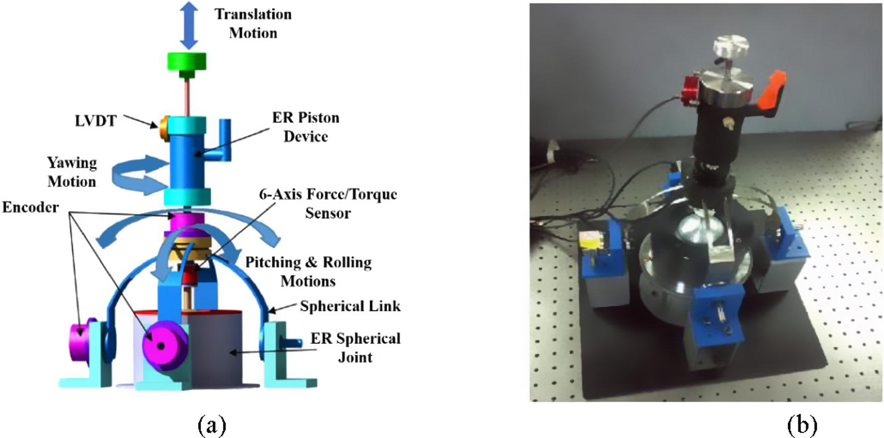
An ER haptic master for robot-assisted surgery (Oh et al., 2013b); (a) configuration, (b) photograph.
On the other hand, a portable active knee rehabilitation orthotic device (AKROD) using ER brake was proposed by Nikitczuk et al. (2010). The AKROD was composed of straps and rigid components for attachment to the leg, with a central hinge mechanism where a gear system was connected as shown in Fig. 2. The key features of the AKROD include: a compact, lightweight design with highly tunable resistive torque capabilities, sensors (encoder and torque), and real-time capabilities for closed-loop computer control for gait retraining. The controllable variable resistance could be achieved through an ER brake connected to the output of the gear system. In this work, two different AKROD controllers were developed that could adapt to the changing environmental parameters such as temperature variation providing consistently accurate and robust control by taking into account the nonlinear behavior of ER fluids. The two AKROD control schemes were an adaptive nonlinear proportional integral (PI) constant torque control and an adaptive sliding mode proportional integral derivative (PID) constant velocity control. These were developed specifically for the purpose of use in rehabilitation, more specifically for isotonic and isokinetic exercises. It has been demonstrated via experimental tests that the proposed device can be effectively applied to wearable rehabilitation mechanisms for human health. One more interesting medical application using ER fluid was proposed in Bansevicius and Virbalis (2007). They proposed a 2-dimensional braille readers using ER fluid based valve matrix mechanism as shown in Fig. 3. The valve matrix realization was achieved by standard laminated electronics plate. The upper and lower copper surfaces can serve as electrodes. An investigation on the valve matrix with valve holes in standard laminate electronics plate has been performed and shown that when a whole matrix is made in the coppered plate, upper and lower copper surfaces serve as electrodes of electric field in the holes. To control the voltage of every hole discretely, individual electrodes on the plates were made in a form of strips, with an angle of 90 between them on both sides of the plate. This design has ensured that the voltage is in only one hole when the voltage between one strip on the upper side and one strip on the lower side is applied. It has been shown that the response time of the valves is around 1–5 ms and the safety of the operator is guaranteed by limiting the maximum current of 1 mA. These results are self-explanatory justifying that the proposed ER valve mechanism can be effectively used as a controllable braille device in which the operator has no contact with the high voltage to be applied to ER fluid domain.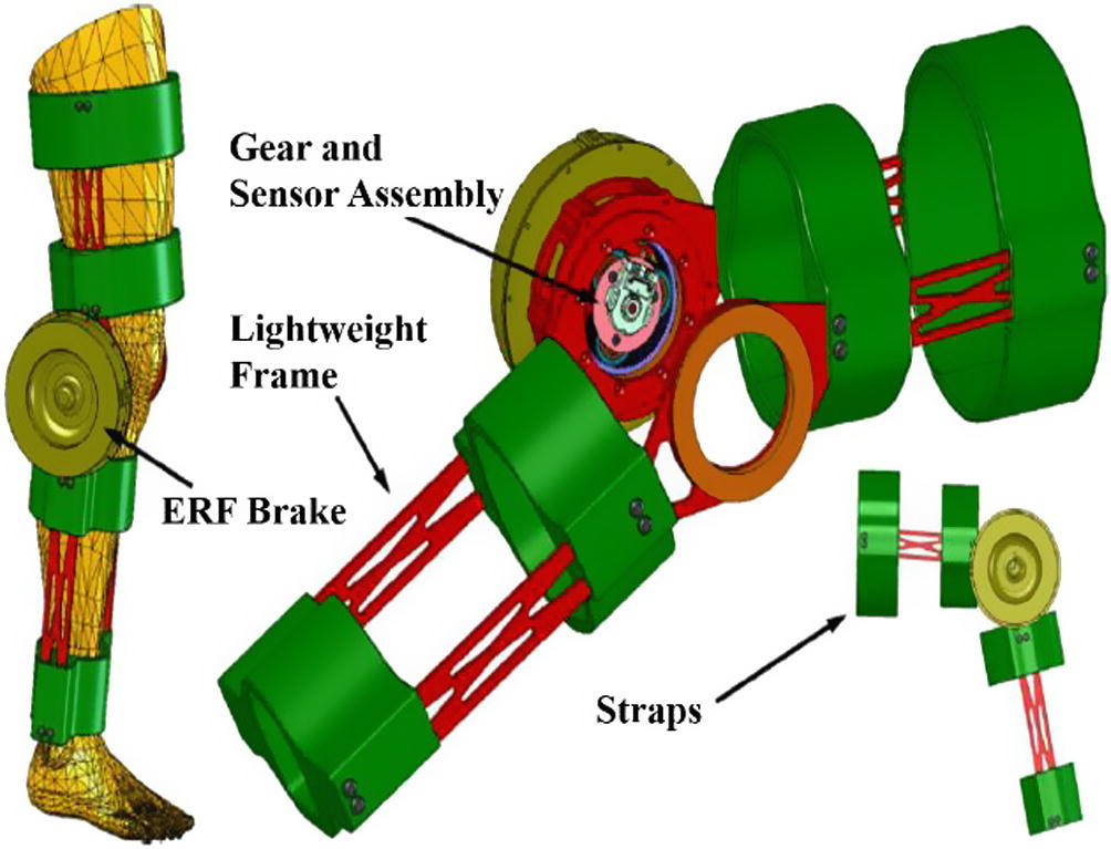
Active knee rehabilitation orthotic device using ERF brake (Nikitczuk et al., 2010).
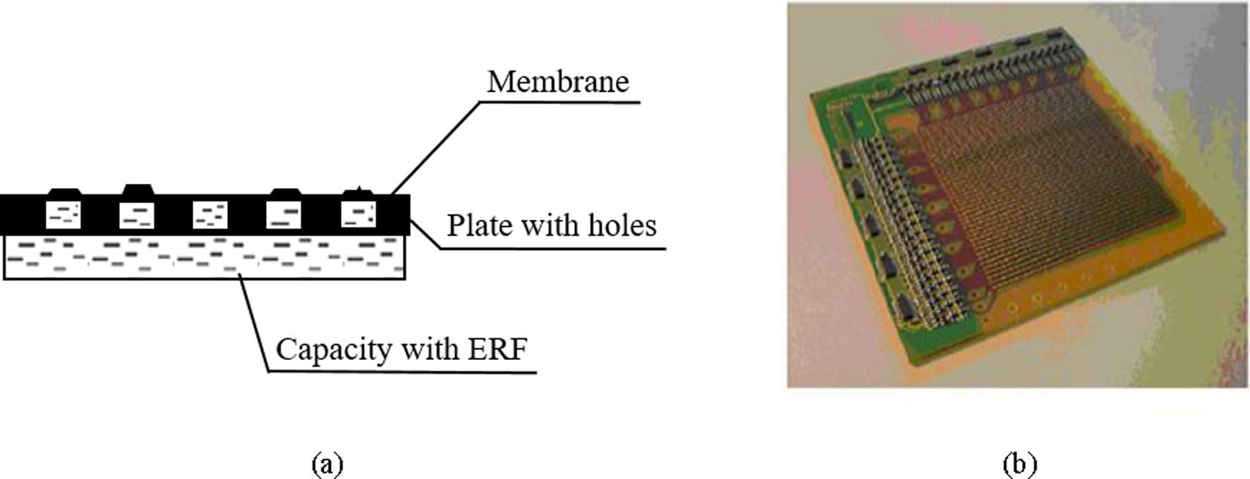
Two-dimensional braille readers based on ERF (Bansevicius and Virbalis, 2007); (a) membrane configuration, (b) matrix of electric field valves.
3 Medical devices using MR fluids
The tactile display utilizing MR fluid was introduced in Liu et al. (2005). In his work, a single cell of MR fluid based tactile display was made as a prototype and its surface force responses were experimentally investigated with respect to the intensity of the magnetic field and probe flexibility. It has been shown that MR fluid is suitable for use as an actuator in a tactile display and the displayed surface information is stable and repeatable. Chouvardas et al. (2008) overviewed various types of tactile displays including MR fluid in terms of the physiological and technological principles. It was reviewed that MR fluid could be one potential candidates for the medical tactile display providing smooth motion with skin-like sensitivity. On the other hand, Yang et al. (2010) introduced a miniature tunable stiffness display using MR fluids which can be applicable to medical haptic system. Fig. 4 shows an overall structure and working principle of the proposed tactile display in this work. When pressed, the elastic spring elongates and MR fluids flow through a gap between the solenoid and the hollow steel shaft. The overflowing fluids make the polydimethylsiloxane (PDMS) membrane swollen at the bottom. After releasing the display, the deformed elastic spring reshapes back to the original configuration and the solenoid also returns to its original position. In order to maximize the resistive force in a small device, the proposed stiffness display was designed such that it has multiple operating modes of MR fluids. The multiple modes include the flow mode (MR fluids flow due to a pressure gradient between the two stationary plates), the shear mode (MR fluids flow between two plates that are moving relative to one another), and the squeeze mode (MR fluids flow between the two plates that are moving in a direction that is perpendicular to their planes). Therefore, the total resistive force can be determined by summing all the stresses developed all of operating modes of MR fluids which could maximize the resistive force in the miniature tactile device. In tactile device researches, virtual surface characteristics was also experimentally investigated by Lee and Jang (2011). They made an MR haptic display as a box type and measured the normal force response using a single magnet and double magnets. It has been shown that the normal force can be affected by several factors such as magnetic flux density and size of the magnet.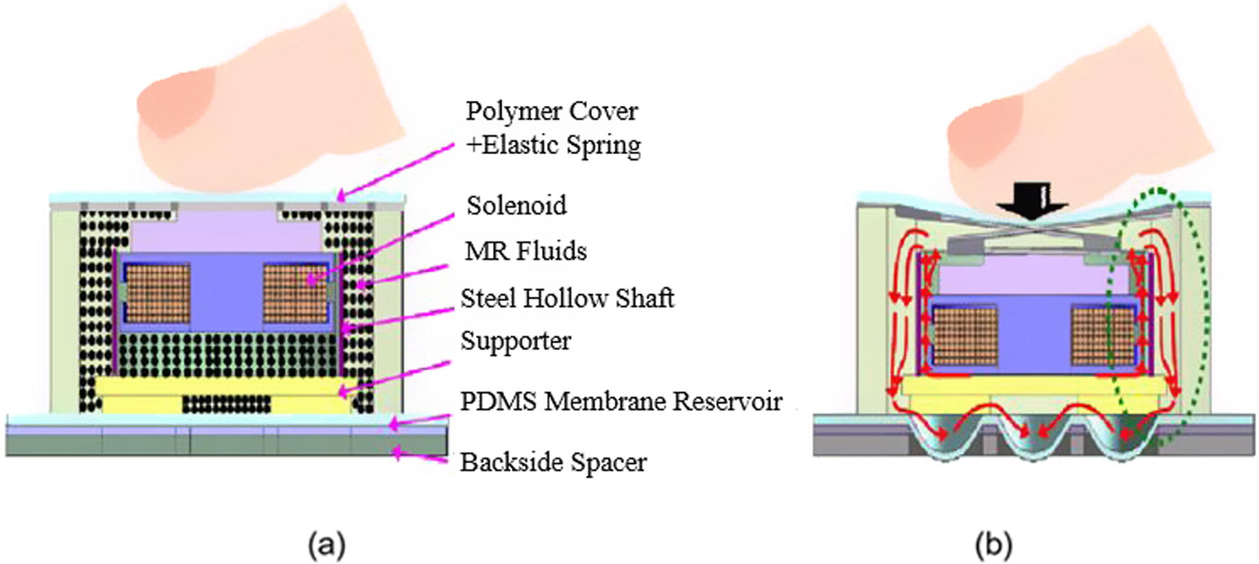
Tunable stiffness display using MR fluids for medical haptic device (Yang et al., 2010); (a) before pressing, (b) after pressing.
Han et al. (2014) proposed an MR tactile display which is applicable for master-slave system in robot-assisted MIS. Fig. 5 shows the configuration of the proposed tactile display in this work. The proposed device is a typical array type with four pins, but the pin array supports an artificial organ. It is made from a rubber diaphragm whose inside is fully filled with MR fluid. The rheological properties of the MR fluid can be changed by applying input current to the two solenoid coils whose turn directions are opposite from each other to generate identical magnetic flux lines. In this structure, the tactile sensations of various biological organs could be realized by adjusting the applied current to each solenoid. The proposed tactile display has been proved by psychophysical tests which were carried out for five test subjects and 20 volunteers, university students aged between 20 and 30 years old. All volunteers were asked to wear a latex glove, touch the surface of the proposed MR tactile display and answer a questionnaire of five questions. Their mean rating value was 3.36 on a five-point scale. This means that one can successfully recognize the tactility to convey through the proposed tactile display. More recently, Kim et al. (2016a) made a new type tactile device using an MR sponge which is directly applicable to the robot-assisted medical surgery. Fig. 6(a) shows a sample of MR sponge cell made of collagen film, open celled polyurethane form and MR fluid. In order to undertake tactile experiments, a 3-axis robot is designed and manufactured as shown in Fig. 6(b). The robot uses four stepper motors. Two of the motors act in the z-axis direction, one motor is involved in the x-axis direction, and the other motor is related to the y-axis direction. The end effector has a 6-axis torque/force sensor and a plastic stick that is shaped like a human fingertip. The specimens and the MR sponge cell are respectively placed on the left and right sides at the bottom of the 3-axis robot. Two electromagnets are used to apply various magnetic fields to the MR sponge cell. In this work, three specimens of pork were used to evaluate the tactile force by controlling the magnetic field; pork, pork rind and pork heart. It has been shown that three specimens have different stress relaxation time and reaction force or torque in each direction. For example, the relaxation time for the x-axis force is 0.32 s for the pork, 0.52 s for the pork rind, and 0.74 s for the pork heart. The relaxation time for the z-axis force is 0.36 s for the pork, 0.48 s for the pork rind, and 0.69 s for the pork heart. The maximum reaction force in the x-direction for the pork, pork rind and pork heart is 0.8 N, 1.0 N and 1.3 N, respectively.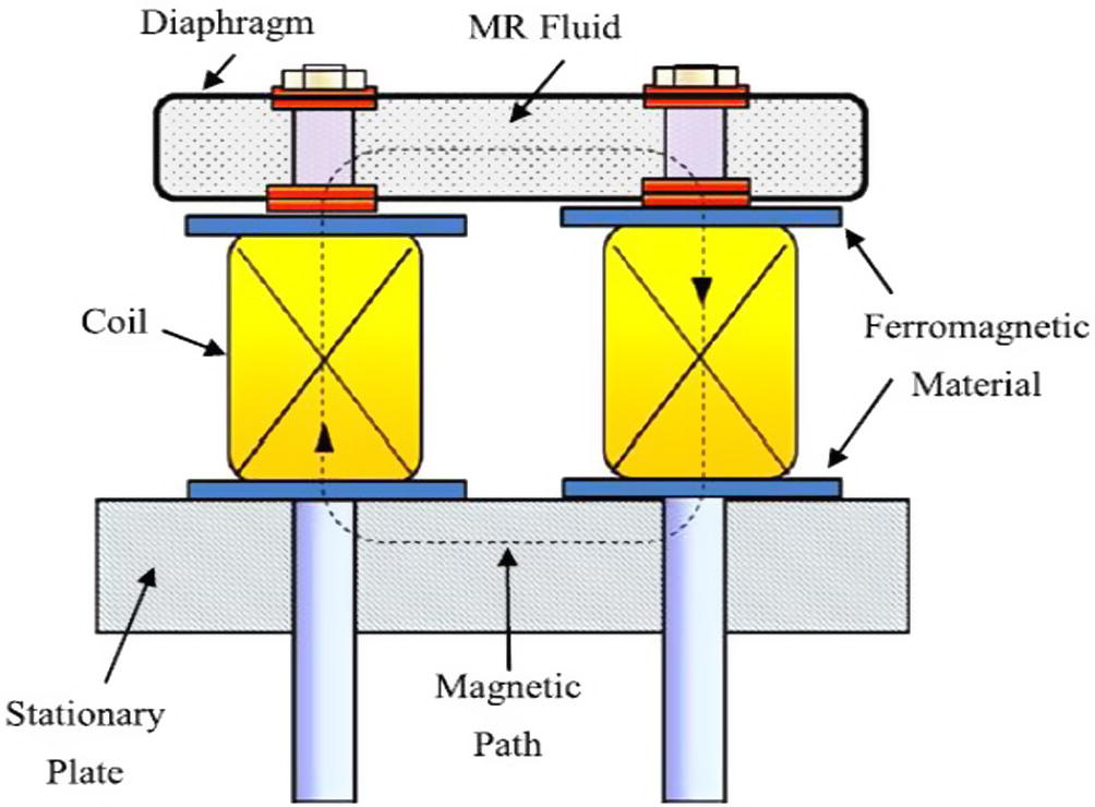
A configuration of the tactile device for testing of palpation force of human body parts (Han et al., 2014).
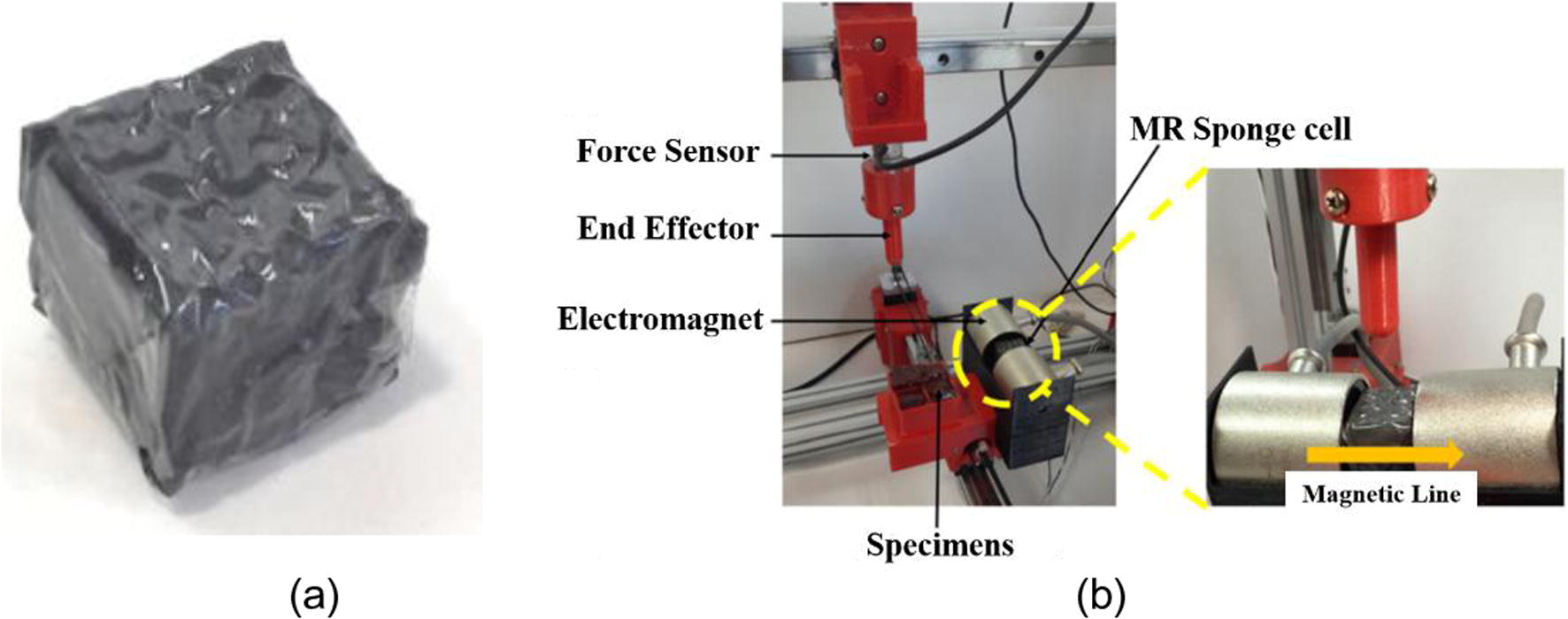
A new tactile device using MR sponge cell (Kim et al., 2016a), (a) sample of MR sponge cell, (b) testing of the reaction force and relaxation time.
It is known that MR fluid is one of potential candidates for various rehabilitation devices or systems since it has several inherent characteristics such as easy controllability of both stiffness and damping properties by the intensity of the magnetic field. Therefore, numerous engineering applications have been proposed by many scholars. Especially, damping force performance of MR damper which can control the damping force according to magnetic field has been intensively worked in Bica (2002, 2004, 2006a,b, 2009), Bica and Choi (2008), Bica et al. (2013, 2015a,b). The basic principle of the prosed medical applications are same that used for MR dampers. Kim and Oh (2001) introduced an above knee prosthesis using a rotary MR damper and tested its effectiveness by adopting leg simulator. It has been shown that the desired knee joint angle can be accurately achieved by controlling the damping force of MR damper. A user-adaptive prosthetic knee utilizing MR brake was proposed and investigated in terms of walking cycles in Herr and Wilkenfeld (2003). The walking cycles consists of stance flexion, stance extension, pre-swing, swing flexion and swing extension. It has been tested that the proposed MR knee prosthesis automatically modulates knee damping values to match the amputee’s gait requirements, accounting for variations in forward speed, gait style and body size. In addition, they have proved that the results achieved in this work can sufficiently support the hypothesis that a user-adaptive control scheme and local mechanical sensing are all that is required for amputees to walk with an increased level of biological realism compared to mechanically passive prosthetic systems. Dong et al. (2006) proposed a variable resistance exercise device using MR dampers. They made two prototypes of MR dampers for the variable resistance knee brace and versatile rehabilitation device. It has been demonstrated from both simulation and experiment that the supervisory control for MR dampers can provide excellent force tracking performance in the presence of parameter uncertainty of the field-dependent nonlinear property of the damper. A leg exoskeleton device using MR damper was proposed and its effectiveness was evaluated in Chen and Liao (2006, 2010). The proposed leg exoskeleton includes braces, MR brake and sensors. The upper brace connected to the waist is bound to the upper leg and the lower brace connected to the foot is bound to the lower leg. The sensors are used to detect the user's walking condition and estimate the needed assistive torque. Two force sensors are mounted on the front and rear sole of the foot to measure the reaction force from the floor. In this work, simulations of walking, sitting down and standing up with the leg exoskeleton were carried out to identify the required torques for normal standing. They concluded from the preliminary result that the proposed leg exoskeleton can provide sufficient assistive torque required for normal walking process. A geometrical optimization for MR rotary brake which can be used as a controllable component for the prosthetic knee was undertaken in Gudmundsson et al. (2010). This work shoed that optimization techniques can aid the design of MR brake as small as possible while maintaining high torque generation. It has been shown that due to the trade-off between many objectives and the multi-objective approach the maximizing the field-induced braking torque may have a strong negative effect on the off-state rotary stiffness. Therefore, they have concluded that a design decision to select the highest tolerable off-state rotary stiffness and to use the valuable simulation data to determine principal design parameters should be carefully considered. Recently, Park et al. developed a prosthetic leg for above-knee amputees using MR damper and commutated motor to achieve both the semi-active and active functions (Park et al., 2016). Fig. 7 shows the schematic configuration and photograph of the proposed leg to be fitted above-knee amputees. The proposed device includes the wearable connector, encoder, flat motor, planetary gear head, gyro sensor, hinge and MR damper. It has shown from experimental tests that the actual knee joint angle fairly follows well the desired angle at low walking velocity. However, as the walking velocity increases the tracking accuracy has been degraded due to the slow time response of the MR damper. Consequently, they concluded that a couple of further researches should be undertaken to enhance control performance and realize in practical environment. Firstly, a proper algorithm of gait cycle which can provide better accuracy than the polynomial prediction function (PPF) for the prediction of the desired values needs to be developed because the proposed prediction method which predicts the knee joint angle from the hip joint angle using the statistical method may be inappropriate when the above-knee amputee encounters disturbance or obstacle. Secondly, the optimal design of MR damper to improve the response time during the turn-off the period should be undertaken to achieve better accuracy in wide range of walking velocities.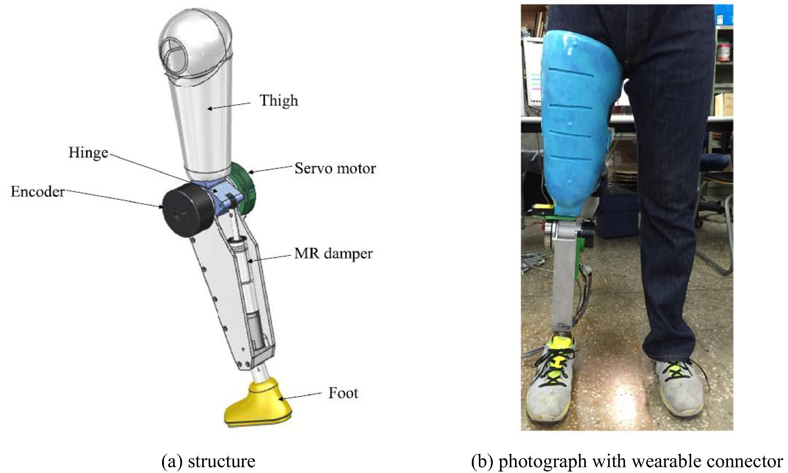
A prosthetic leg for above-knee amputees using MR damper (Park et al., 2016).
On the other hand, Furusho et al. (2007) developed a controllable ankle-foot orthosis using MR brake as shown in Fig. 8. They made two different prototypes using shear mode MR brakes which can produce maximum torque of ankle joint; 0.71 Nm and 11.8 Nm, respectively. They tested the ankle angle without and with control action in the walking state. It has been shown that by controlling the ankle torque using MR brake the subject can maintain the dorsal flexion and prevent the drop foot in swing phase. In addition, they have demonstrated that the higher bending moment and shorter walking cycle are achieved by activating MR brake which in turn can prevent drop foot in swing phase and slap foot at heel strike. They improved the model developed in Furusho et al. (2007) by making as a compact size while maintaining the maximum torque of 10 Nm (Kikuchi et al., 2010a,b). In this work, they used an accelerometer and a rotary potentiometer to determine the state of the gait. To test the feasibility of the newly developed an intelligent controllable ankle-foot orthosis (i-AFO), they conducted gait experiments on a patient with post-Guillan–Barre syndrome. The experiments showed that the i-AFO correctly controlled the angular velocity of the ankle joint by means of the velocity controller. The i-AFO worked as a velocity controller in the loading response and an angle limiter in the swing phase. They concluded that these functions can improve the abnormal gait of the subject.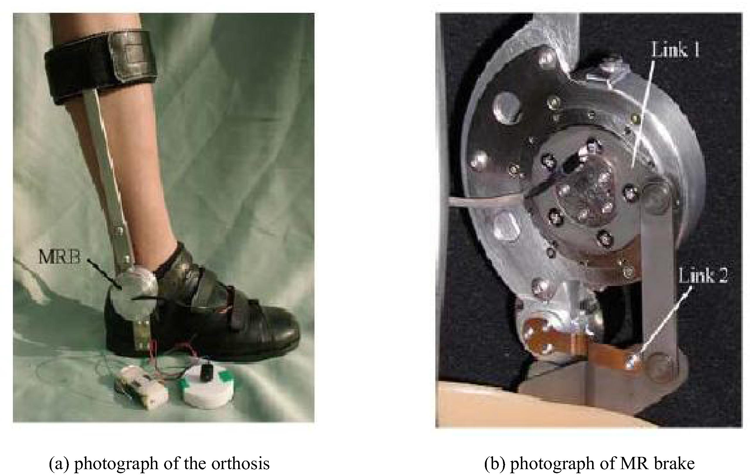
An ankle-foot orthosis using MR brake (Furusho et al., 2007).
It is known that various types of haptic systems (or haptic master system) have been developed for the application of the medical fields such as the robot-assisted minimally invasive surgery (RMIS). The haptic systems used for the medical sector can be classified into two different modes; active mode and semi-active mode. In general, the active mode is realized using servo motors or hydraulic actuators and hence controlled (desired) repulsive force or torque can be easily sensed by the operator. However, the stability of the haptic system executed by the active mode may be failed due to abnormal feedback control signals. Therefore, recently semi-active types of haptic systems are widely introduced and developed. Among the semi-active types, most attractive and practically feasible one is to use MR fluid. In 2004, a new dissipative haptic system actuated by MR brakes was introduced and preliminary round of testing with human operators was used to evaluate each control technique showing good torque tracking responses (Reed and Book, 2004). Based on this outstanding control performance, many researches related to MR brake were developed for the haptic application (Liu et al., 2006; Avraam et al., 2010). Among them, Senkal et al. proposed the compact size of MR brake featuring a high torque generation (Senkal and Gurocak, 2010). In this research, a serpentine magnetic flux path which enabled the design of a brake that is 33% smaller in diameter than the commercial brake yet produces 2.7 times more torque was made and tested. In addition, O-Rings were used to seal the fluid which could result in increased off-state friction. Senkal et al. (2011) proposed MR haptic system as a surgical aid for dental implant surgery to get several benefits such as decreased dependence on the surgeon’s skill, accurate implant positioning and increased overall safety of the operation procedure. Fig. 9 shows the dental surgery and the haptic device made in this work. The designed haptic device prototype consists of four components: MR-brakes; position sensors; a 6-DOF force sensor; and a hand piece for drilling. Pen-based haptic devices (PHANToM) were taken as an example in the design of this first prototype. Hence, three joints were actuated with MR brakes for creating haptic feedback and the remaining three joints were left unactuated at the wrist to provide motion in 6 DOF. The end effector of the haptic interface used a spherical joint at the wrist and a small drill bit at the end of the hand piece. The x-y-z coordinate of the drill bit could be constrained using the haptic feedback created by the MR brakes. An alignment plate with a sleeve was attached onto the drill bit to provide angular guidance during user experiments. It has been shown that during the haptic drilling experiments, deflection causes the positioning errors, despite the rigid construction of the haptic arm. This is a challenging issue, since the arm needs to be lightweight and the application requires very strict positioning accuracy. In addition, the anisotropic behavior of the system, as indicated by different error levels in the x, y, and z directions, contributing to the positioning errors was observed. It has been mentioned in this work that the current system cannot achieve the level of accuracy of robotic systems in the x direction yet, but it is promising as a first prototype.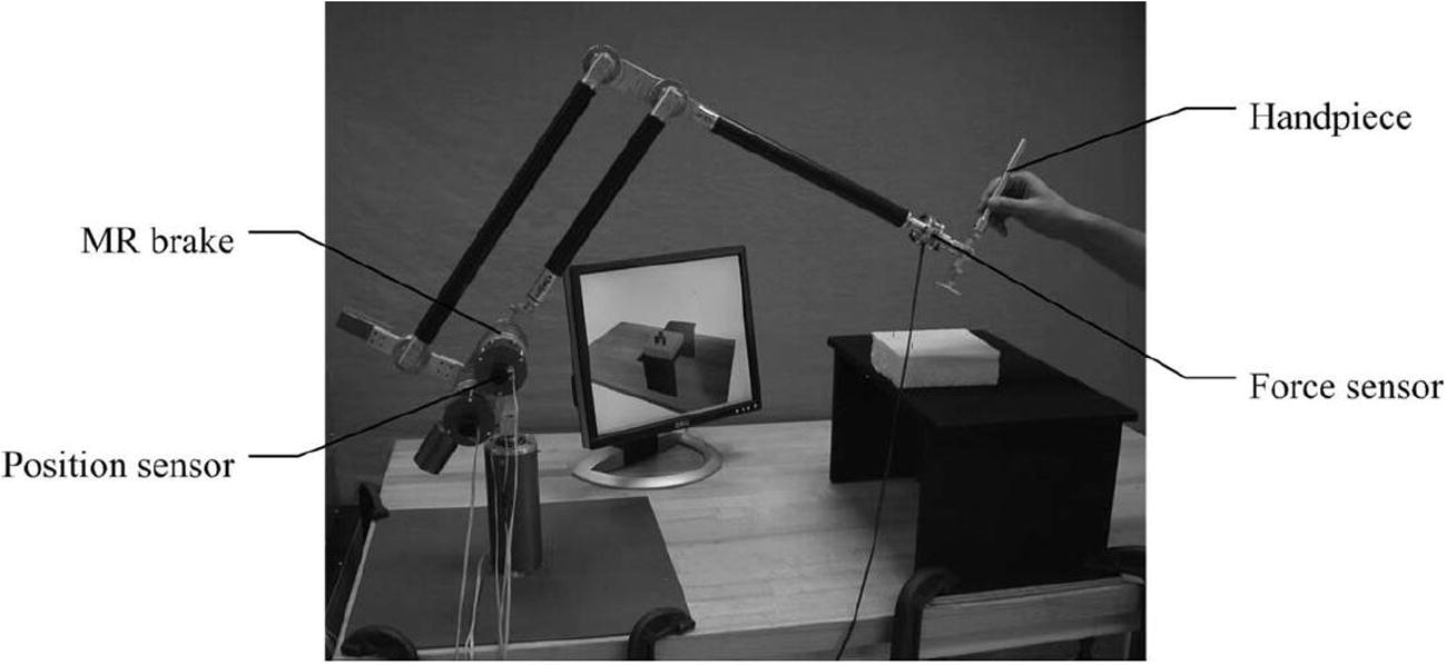
A haptic interface with MR brake for dental implant surgery (Senkal et al., 2011).
Senkal and Gurocak (2011) proposed a new type of the haptic joystic featured by three air muscles and a spherical MR brake which can apply forces 2-DOF. In this work, the hybrid control approach blended the forces from the active air muscle actuators with the forces from the spherical MR brake actuator. The benefit of the hybrid actuator could be observed in simulating interactions with elastic virtual objects. It has been demonstrated that using the MR brake and the air muscles, the stable stiffness that can be simulated at high speeds dramatically increases. Thus, they have concluded that the proposed haptic joystic can be employed in applications including computer games, medical training applications, rehabilitation and in teleoperation of equipment where high force feedback in a compact work volume may be desirable. They proposed another configuration of the haptic device using a Hall-effect sensor and a new compact MR brake (Gonenc and Gurocak, 2012). The Hall-effect sensor was embedded to eliminate the hysteresis and reduce off-state torque of MR brake through closed-loop magnetic induction control. In this work, the desired force profile was divided into two input signals as smoothened profile signal and fine detail signal to operate the brake and the motor in harmony with a simple control scheme. The smoothened profile signal was then mapped into magnetic induction domain to form the MR brake command signal. Another contribution of the research was canceling the hysteretic behavior of the brake through the use of an embedded Hall-effect sensor, which provided more accurate and easy control of the device. The torque output was regulated based on the sensed magnetic induction in the brake instead of the magnetic field strength. Measured magnetic induction values provided a good estimate of the individual torque output of the brake. It has been also shown that the hybrid actuator consisting of motor and MR brake can provide significant improvements in terms of reflecting realistic tissue behavior during a virtual needle insertion, removal and collision with a bone compared to using a single actuator.
The research trend on the development of the haptic systems for last two years has been rapidly changed to the implementation of the surgery operating associated with the RMIS. In general, the teleoperated robot–assisted haptic catheter minimally invasive surgery system consists of human operator, haptic master subsystem, communication channel, slave manipulator subsystem, and the patient environment. Yin et al. (2016) proposed a new teleoperated haptic robot-assisted catheter operating system using MR fluid container. Fig. 10 shows the conceptual idea and fabricated catheter interfaces developed in this work. The haptic catheter operation subsystem based on exploiting MR fluids was proposed, which consists of electromagnetic design, haptic catheter interface design, and haptic calibration mechanism design. Three spacers which gave MR fluids annular duct design more freedom according to the requirements, were designed to adjust the gap between two coils to further adjust magnetic field intensity through the MR fluids container. The diameter of the copper wire of the coil is 1.6 mm and each of coil turns is 1200 T. The bobbin of the coil and the stage are made of aluminum. Iron core is used to increase the magnetic field in the center. The yoke used to support the coils is also made of the steel, and all other components are made of nonmagnetic material. In this work, the following tests were undertaken; the distribution of the magnetic field intensity, the friction measurement of the haptic interface, the calibration of the haptic force, the measurement of the haptic force at different insertion frequencies, and the hysteretic characteristics of MR fluid. These experimental results have demonstrated that the designed teleoperated robot–assisted catheter haptic minimally invasive surgery master operating system can provide a haptic sensation to the surgeon for improving the safety of surgery as well as maneuverability. It has been also shown that the haptic calibration experiments based on the designed catheter haptic operation system and hysteretic characteristics test of MR fluids can be easily done due to the controllability of the field-dependent rheological properties of MR fluid. In addition, it has been observed that the hysteretic characteristics of MR fluids have no impact on the haptic force. Using the proposed haptic system, the surgeon can obtain a kinesthetic sensation based on the slave system measurement by precise control of the current generated magnetic field intensity. However, in order to successfully complete the surgery operation the robotic catheter haptic operation master system should be able to provide a kinesthetic sensation to the surgeon to ensure the safety of catheter minimally invasive surgery. They have concluded that the designed catheter haptic master operation system can be used not only as a console used in teleoperated robot–assisted surgery scenario but also for non-experienced surgeon training.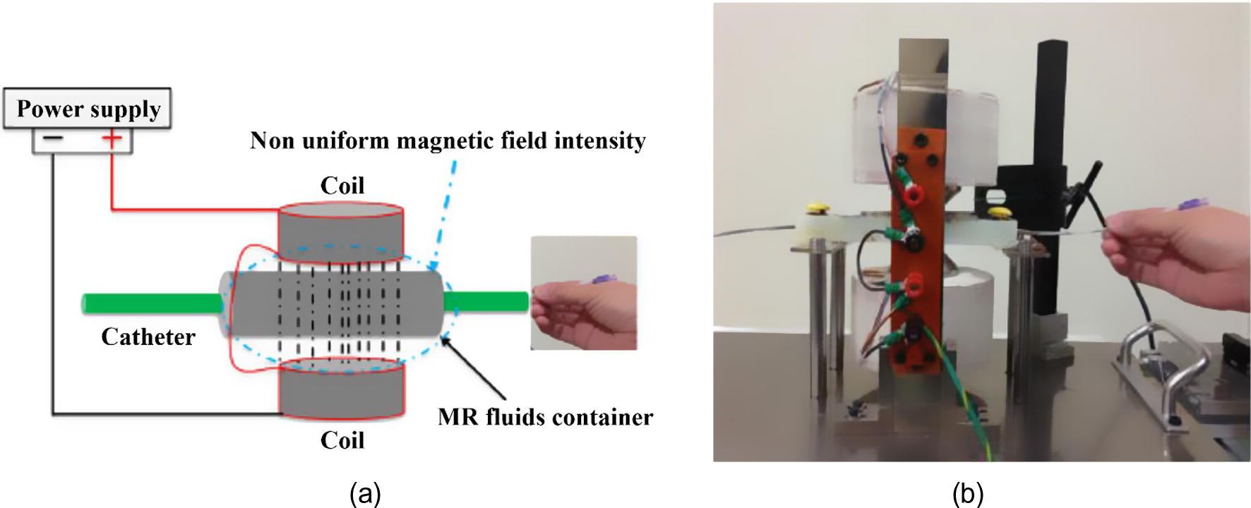
A haptic interface for the robot-assisted catheter operating system using MR fluids (Yin et al., 2016); (a) haptic configuration, (b) fabricated catheter haptic interface.
Recently, a miniature haptic button was proposed using MR fluid to convey realistic and vivid haptic sensations to users in small electronics (Yang et al., 2014; Ryu et al., 2016). The schematic view and operating method of the miniature MR actuator is shown in Fig. 11. The housing with a yoke contains a solenoid, a cone-shaped plunger, an elastic spring, and MR fluid. The solenoid coil is attached to the bottom of the housing surrounding the yoke, and the plunger is placed inside the solenoid coil. A housing spacer and a housing cover are mounted to the top of the housing, and the contact plate is fixed to the upper end of the plunger. The elastic spring is placed between the housing cover and the contact plate, and it provides an elastic restoring force to bring the contact plate to its initial position upon removing the input current and releasing the actuator. Since the housing with the inclined yoke, the cone-shaped plunger, and the housing cover is made by a ferromagnetic material, those parts guide magnetic fields generated from the solenoid coil, creating a closed magnetic circuit. The housing contains MR fluid, and the fluid flows through the gaps between the yoke and the plunger. When a user presses the MR actuator, MR fluid flows upward from the inclined gap between the yoke and the plunger. Once an input current is applied to the solenoid coil, MR fluid builds up particle chains in the inclined gap, producing resistive forces. The proposed miniature MR actuator was designed to integrate multiple operating modes of MR fluid for maximizing the resistive force in a given size of the actuator. The force contributed by the squeeze mode exponentially decreases when the gap distance between the plunger and the housing in the actuator increases. Thus, the cone-shaped plunger design was employed to compensate dramatic decrease of the squeeze mode force. Moreover, the cone-shaped design allowed further reducing the height of the actuator as compared with an equivalent MR actuator with a cylindrical-shaped plunger design. It has been shown from experimental results that the pressed depth is gradually increased according to the gradual increase of the resistive force and the desired resistive force suddenly drops around the 0.65 mm pressed depth. This indicates that the proposed impedance sensing mechanism reliably gauges the user’s pressed depth, and the designed control system works properly to produce the desired force according to the measured pressed depth. Therefore, they have made conclusions that the control system using the impedance sensing method can reliably provide various force profiles with respect to the gauged pressed depth and hence it can be applied to real-world haptic applications such as medical interfaces, game interfaces, mobile phones, and so on.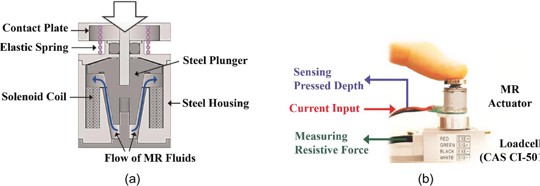
A miniature MR actuator for haptic applications (Ryu et al., 2016); (a) actuator configuration, (b) experimental setup for measuring the resistive force.
Recently, Oh et al. developed 4-DOF haptic master for application to the robot-assisted surgery (Oh et al., 2014). Fig. 12 presents the schematic configuration and photograph of the manufactured haptic master featuring MR clutches. The proposed MR haptic master consists of two distinct actuators: a bi-directional MR clutch with a planetary gear system and an MR clutch with a bevel gear system. The resistance to the motion of the operator is transmitted from these MR actuators via the gimbal mechanism. In the MR actuator mechanisms, the force reflection is realized by the MR fluid. In order to realize the force reflection for the pitching and rolling rotational motions, two bi-directional MR clutches and the planetary gear system incorporated with the gimbal mechanism is used. The bidirectional MR clutch consists of the two coils, the two rotors and one outer casing. Two rotors are fixed to their respective shafts, which are transmitted from a planetary gear system as the driving bi-output source. After verifying the effectiveness of the proposed haptic master showing excellent repulsive torque tracking responses (Oh et al., 2014), it has been applied to the simple cutting surgery associated with the visual feedback control method (Choi et al., 2015). Fig. 13(a) shows a block diagram for the cutting surgery using the proposed haptic master featuring MR clutches. When the operator manipulates the master, the motion commands are transferred to the slave robot via an analog/digital-digital/ analog data acquisition system installed on commercial dSpace. The movement of the master is measured by encoders and its frictional torques are determined by torque sensors. While performing the surgical tasks according to the motion commands, the slave robot transmits the force data from the force sensor which is installed in the middle of the instrument. The force sensor measures the contact force that the slave robot perceives, and the MR haptic master allows the operator to feel this measured force through the degree of solidification of the MR fluid. The visual image is obtained by a vision sensor and is transmitted to the microprocessor in real time. According to the testing condition, the haptic and visual feedback systems can be turned on or off. The sampling frequency was set to 1 kHz in experimental implementation. Fig. 13(b) presents two different vision images and control results for the repulsive force in the x and y direction. Because the MR bi-directional clutch and MR handle clutch compensate for the inertial and gravitational forces of the MR haptic master in real time, the actual repulsive forces reflect the desired repulsive forces accurately. The average force error does not exceed 0.07 N, and the standard deviation is 0.062 N. They have concluded that when the vision devices are attached associated with the digital image processing can enhance the practical surgery performance of RMIS helping the distinguishing the tumor from the organ more clearly. More recently, Kim et al. (2016b) proposed a mathematical model for the reaction force occurred during insertion by considering deformation mode, rupture mode and cutting mode and verified its effectiveness through a comparative work with the measured results achieved by controlling the haptic device featuring MR clutches. In the test, three different types of boar tissues which are hard, medium and soft tissues were used. The subjects of the experiment were classified into hard tissue, medium tissue, and soft tissue, and they are incised by the scalpel of the measurement device. The hard tissue includes skin and flesh, the medium tissue is flesh without skin, and the soft tissue is boar liver. The reaction force information was measured in the vertical direction and horizontal direction. The scalpel blade makes a crack in the tissue in the vertical direction and propagates the crack. After incision in the vertical direction, the scalpel moves in the horizontal direction. It has been demonstrated that the closed-loop PID controller is more accurate than the open loop controller. However, the system with the PID feedback controller had a weakness in the external disturbance that caused system oscillation. Therefore, they have concluded that a new controller such as sliding mode controller that has robustness to external disturbance needs to be implemented for the RMIS subjected to parameter variations and disturbances.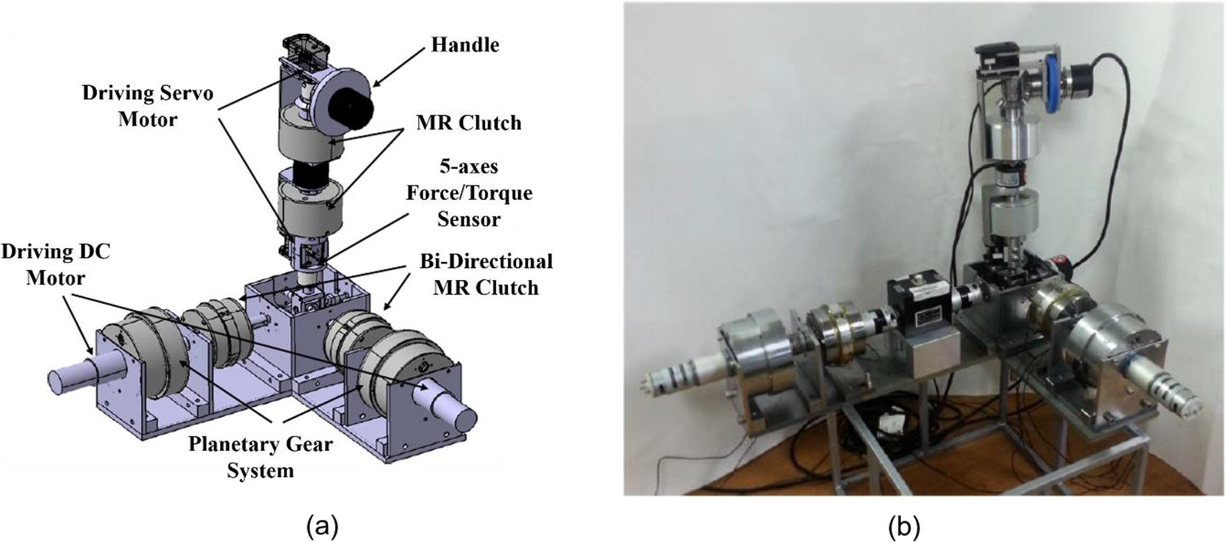
A haptic master for robot surgery using bi-directional MR clutches (Oh et al., 2014); (a) configuration of the haptic master, (b) prototype of the haptic master.
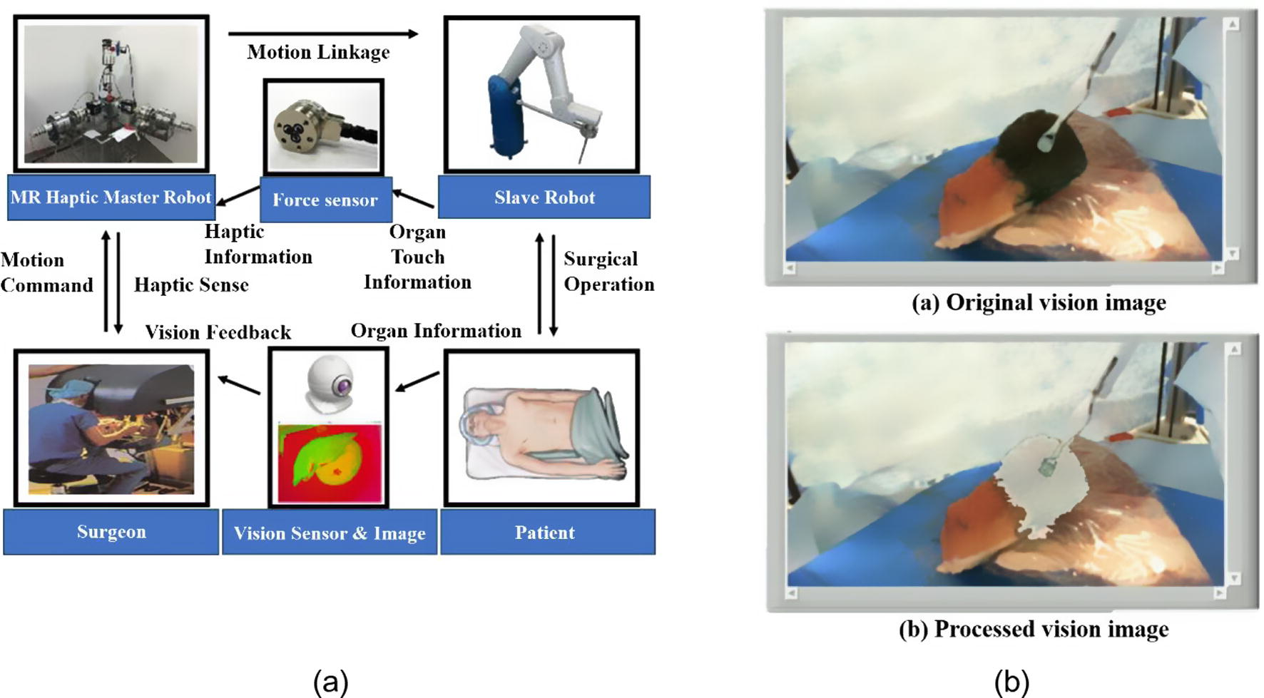
A robot-assisted surgery diagram using the MR haptic master (Choi et al., 2015); (a) surgery diagram, (b) original and processed images.
4 Conclusion
In this topical review article, several medical devices and systems utilizing smart ER and MR fluids were introduced and their technology capabilities and limitations for practical implementation were discussed. Especially, the operating principle and mechanical structure of each medical device has been fully described followed by the detailed discussion of merits and problems to overcome for practical use. It has shown that at this moment the most promising medical applications using smart fluids are several types of haptic masters activated by ER/MR brakes and ER/MR clutches. These haptic masters can provide a smooth motion for robot surgery with robust stability during surgical operation due to the continuous controllability of damping property of smart fluids. It has also surveyed that various rehabilitation systems can be practically realized soon by utilizing easy controllability of force and torque which are required for optimal training program for the recovery from injury. This review provides very useful information on the potential research opportunities and emerging technologies using smart fluids for the innovative medical devices of the future. It is remarked that continuous advances in the synthesis of smart fluids are likely to motivate the creativity of researchers seeking to innovative and advanced medical devices and systems integrated with appropriate control methodologies. It is noted that the technology using smart fluid is expected to change everyday life and boost medical industry.
Acknowledgments
This work was supported by the National Research Foundation (NRF) grant directed by the South Korea government (MSIP; Ministry of Science, ICT & Future Planning) (No. 2017R1C1B5018204).
References
- Computer controlled rotational MR-brake for wrist rehabilitation device. J. Intell. Mater. Syst. Struct.. 2010;21(15):1543-1557.
- [Google Scholar]
- Two-dimensional Braille readers based on electrorheological fluid valves controlled by electric field. Mechatronics. 2007;17(10):570-577.
- [Google Scholar]
- Damper with magnetorheological suspension. J. Magn. Magn. Mater.. 2002;241(2):196-200.
- [Google Scholar]
- Magnetorheological suspension electromagnetic brake. J. Magn. Magn. Mater.. 2004;270(3):321-326.
- [Google Scholar]
- Electrical conductivity of magnetorheological suspensions based on iron microparticles and mineral oil in alternative magnetic field. J. Ind. Eng. Chem.. 2006;12(5):806.
- [Google Scholar]
- The influence of temperature and of a longitudinal magnetic field upon the electrical conductivity of magnetorheological suspensions. Physica B. 2006;371(1):145-148.
- [Google Scholar]
- Electroconductive magnetorheological suspensions: production and physical processes. J. Ind. Eng. Chem.. 2009;15(2):233-237.
- [Google Scholar]
- Preparation and electro-thermoconductive characteristics of magnetorheological suspensions. Int. J. Mod. Phys. B. 2008;22(29):5041-5064.
- [Google Scholar]
- Physical characteristics of magnetorheological suspensions and their applications. J. Ind. Eng. Chem.. 2013;19(2):394-406.
- [Google Scholar]
- Magnetodielectric effects in hybrid magnetorheological suspensions. J. Ind. Eng. Chem.. 2015;22:53-62.
- [Google Scholar]
- Influence of magnetic field on dispersion and dissipation of electric field of low and medium frequencies in hybrid magnetorheological suspensions. J. Ind. Eng. Chem.. 2015;27:334-340.
- [Google Scholar]
- Chen, J., Liao, W.H., 2006. A leg exoskeleton utilizing a magnetorheological actuator. In: Robotics and Biomimetics, 2006. ROBIO'06. IEEE International Conference on (pp. 824–829). IEEE.
- Design, testing and control of a magnetorheological actuator for assistive knee braces. Smart Mater. Struct.. 2010;19(3):035029.
- [Google Scholar]
- A new visual feedback-based magnetorheological haptic master for robot-assisted minimally invasive surgery. Smart Mater. Struct.. 2015;24(6):065015.
- [Google Scholar]
- Smart rehabilitation devices: Part I-force tracking control. J. Intell. Mater. Syst. Struct.. 2006;17(6):543-552.
- [Google Scholar]
- Furusho, J., Kikuchi, T., Tokuda, M., Kakehashi, T., Ikeda, K., Morimoto, S., Ellipsis, Akazawa, Y., 2007. Development of shear type compact MR brake for the intelligent ankle-foot orthosis and its control; research and development in NEDO for practical application of human support robot. In Rehabilitation Robotics, 2007. ICORR 2007. IEEE 10th International Conference on (pp. 89–94). IEEE.
- Virtual needle insertion with haptic feedback using a hybrid actuator with DC servomotor and MR-brake with Hall-effect sensor. Mechatronics. 2012;22(8):1161-1176.
- [Google Scholar]
- A geometrical optimization of a magneto-rheological rotary brake in a prosthetic knee. Smart Mater. Struct.. 2010;19(3):035023.
- [Google Scholar]
- Control of an ER haptic master in a virtual slave environment for minimally invasive surgery applications. Smart Mater. Struct.. 2008;17(6):065012.
- [Google Scholar]
- Force feedback control of a medical haptic master using an electrorheological fluid. J. Intell. Mater. Syst. Struct.. 2007;18(12):1149-1154.
- [Google Scholar]
- Design and experimental evaluation of a tactile display featuring magnetorheological fluids. Smart Mater. Struct.. 2014;23(7):077001.
- [Google Scholar]
- Tracking controls of torque and force of 4-degree-of-freedom haptic master featuring smart electrorheological fluid. J. Intell. Mater. Syst. Struct.. 2016;27(7):915-924.
- [Google Scholar]
- User-adaptive control of a magnetorheological prosthetic knee. Ind. Robot: Int. J.. 2003;30(1):42-55.
- [Google Scholar]
- Kikuchi, T., Tanida, S., Otsuki, K., Yasuda, T., & Furusho, J., 2010. Development of third-generation intelligently controllable ankle-foot orthosis with compact MR fluid brake. In Robotics and Automation (ICRA), 2010 IEEE International Conference on (pp. 2209–2214). IEEE.
- Development of a compact magnetorheological fluid clutch for human-friendly actuator. Adv. Rob.. 2010;24(10):1489-1502.
- [Google Scholar]
- Kim, J.H., Oh, J.H., 2001. Development of an above knee prosthesis using MR damper and leg simulator. In: Robotics and Automation, 2001. Proceedings 2001 ICRA. IEEE International Conference on (Vol. 4, pp. 3686–3691). IEEE.
- A new tactile device using magneto-rheological sponge cells for medical applications: experimental investigation. Sens. Actuators, A. 2016;239:61-69.
- [Google Scholar]
- Force modeling for incisions into various tissues with MRF haptic master. Smart Mater. Struct.. 2016;25(3):035008.
- [Google Scholar]
- Virtual surface characteristics of a tactile display using magneto-rheological fluids. Sensors. 2011;11(3):2845-2856.
- [Google Scholar]
- Repulsive force control of minimally invasive surgery robot associated with three degrees of freedom electrorheological fluid-based haptic master. Proc. Inst. Mech. Eng. C: J. Mech. Eng. Sci.. 2014;228(9):1606-1621.
- [Google Scholar]
- Single cell magnetorheological fluid based tactile display. Displays. 2005;26(1):29-35.
- [Google Scholar]
- Development of an MR-brake-based haptic device. Smart Mater. Struct.. 2006;15(6):1960.
- [Google Scholar]
- Active knee rehabilitation orthotic device with variable damping characteristics implemented via an electrorheological fluid. IEEE/ASME Trans. Mechatron.. 2010;15(6):952-960.
- [Google Scholar]
- A 4-DOF haptic master using ER fluid for minimally invasive surgery system application. Smart Mater. Struct.. 2013;22(4):045004.
- [Google Scholar]
- Control of repulsive force in a virtual environment using an electrorheological haptic master for a surgical robot application. Smart Mater. Struct.. 2013;23(1):015010.
- [Google Scholar]
- Design of a 4-DOF MR haptic master for application to robot surgery: virtual environment work. Smart Mater. Struct.. 2014;23(9):095032.
- [Google Scholar]
- Design and control of a prosthetic leg for above-knee amputees operated in semi-active and active modes. Smart Mater. Struct.. 2016;25(8):085009.
- [Google Scholar]
- Reed, M.R., Book, W.J., 2004. Modeling and control of an improved dissipative passive haptic display. In Robotics and Automation, 2004. Proceedings. ICRA'04. 2004 IEEE International Conference on (vol. 1, pp. 311–318). IEEE.
- Mechanical and psychophysical performance evaluation of a haptic actuator based on magnetorheological fluids. J. Intell. Mater. Syst. Struct.. 2016;27(14):1967-1975.
- [Google Scholar]
- Serpentine flux path for high torque MRF brakes in haptics applications. Mechatronics. 2010;20(3):377-383.
- [Google Scholar]
- Haptic joystick with hybrid actuator using air muscles and spherical MR-brake. Mechatronics. 2011;21(6):951-960.
- [Google Scholar]
- Passive haptic interface with mr-brakes for dental implant surgery. Presence. 2011;20(3):207-222.
- [Google Scholar]
- Advances in an electrorheological fluid based tactile array. Displays. 1998;18(3):135-141.
- [Google Scholar]
- Development of a miniature tunable stiffness display using MR fluids for haptic application. Sens. Actuators, A. 2010;163(1):180-190.
- [Google Scholar]
- A miniature magneto-rheological actuator with an impedance sensing mechanism for haptic applications. J. Intell. Mater. Syst. Struct.. 2014;25(9):1054-1061.
- [Google Scholar]
- Design and experimental evaluation of a teleoperated haptic robot–assisted catheter operating system. J. Intell. Mater. Syst. Struct.. 2016;27(1):3-16.
- [Google Scholar]


