

Translate this page into:
Numerical modeling of the electrical properties plasma argon in a RF magnetron sputtering and with Einstein's relation of electron diffusivity
⁎Corresponding author. fethi.khelfaoui@gmail.com (F. Khelfaoui) khelfaoui.fe@univ-ouargla.dz (F. Khelfaoui)
-
Received: ,
Accepted: ,
This article was originally published by Elsevier and was migrated to Scientific Scholar after the change of Publisher.
Peer review under responsibility of King Saud University.
Abstract
Numerical modeling of RF magnetron sputtering discharge of argon plasma properties, using a one-dimensional time-dependent fluid model in presence of the magnetic field, has been developed. The model is based on continuity equation and electron temperature equation coupled with Poisson’s equation. The electron mobility depends on magnetic field and the electron diffusivity is assumed to be dependent of electron energy by Einstein's relation. The flux is calculated by Scharfetter and Gummel schemes. Numerical simulations were resolved by using the Finite Volume Method (FVM) and the Thomas algorithm. The obtained results for the electrical properties, electron and ion densities, electrical potential, electric field and electron temperature, are in good agreement with previous works. A parametric study varying the magnetic field intensity on the discharge properties is done.
Keywords
Magnetron sputtering
Electrical properties
Fluid model
Electron diffusivity
Einstein's relation
SG Scheme
Thomas algorithm
Argon gas

1 Introduction
Magnetron sputtering system is one of the most popular techniques that have been widely used for deposition of thin films in material processing and semiconductor industry. It offers two main advantages. Firstly, the ease with which one can deposit on large area due to the good plasma uniformity. Secondly, the deposition rate is higher (Kolev and Bogaerts, 2004). Because of the many applications, many experimental, analytical and numerical researches were made during the last decades in order to understand its principles (Palmero et al., 2004). For numerical models, we can apply a fluid model (Costin et al., 2005; Cramer, 1997; Kumar and Roy, 2005; Ballah et al., 2009), a particle model (Benyoucef et al., 2011) or their combination (Kolev and Bogaerts, 2004). A number of models of magnetron discharges have been reported. Works in regimes DC (Kolev and Bogaerts, 2004; Costin et al., 2005; Cramer, 1997) or RF (Palmero et al., 2004; Kumar and Roy, 2005) have studied in one dimension (Palmero et al., 2004; Cramer, 1997; Ballah et al., 2009) and two dimensions (Kolev and Bogaerts, 2004; Costin et al., 2005; Kumar and Roy, 2005). It was considered constant the electron energy and variable the electron diffusivity. The electron diffusivity has been taken from Einstein's relation. In literature, the studied works are in DC regime (Lin and Adomaitis, 1998; Bouchikhi, 2012; Bouchikhi and Hamid, 2010; Tebani and Hennad, 2013) and in RF regime (Dalvie et al., 1993; Lin and Adomaitis, 2001), and without a magnetic field.
In this work, we present a model for RF magnetron sputtering, in one-dimensional time-dependent fluid model. In an argon plasma, we calculate the electron and the ion densities and the electron energy (or electron temperature) using the Boltzmann equation; the electric field distribution can be obtained from Poisson’s equation. The electron mobility depends on the magnetic field and the electron diffusivity is related to electron energy by Einstein's relation.
In Section 2, we present the principal equations of the fluid model. In section 3, we present the expression of the electron mobility. The section 4 presents the numerical model based on Finite Volume Method (FVM); Exponential scheme and Thomas algorithm are used to solve the coupled equations systems. The results of this work are presented in section 5. Electron and ion densities, electrical potential, electric field and electron temperature are calculated for the argon RF 13,56 MHz magnetron discharges. In sub-section 5.1, we present some typical simulation results for various times of the RF cycle. In sub-section 5.2, we present the effect of the magnetic field. We present a discussion and comments on the various results. In the last section, we close this work by a conclusion and perspectives.
2 Description of the fluid model
The fluid model was proposed in order to study describe the kinetics of charged particles, in a RF magnetron sputtering system. The considered coupled equations of the model are the continuity equation (1), the electron energy for the electron temperature equation (2) and Poisson’s equation (3). We resolve these equations for electron and ion densities, electrical potential and electron temperature. Electric field and ionization rates can be deduced from these solutions.
Due to the strong coupling of the fluid equations in presence of the magnetic field, some assumptions are required in order to simplify the numerical calculation (Costin et al., 2005).
The flux term is calculated by a transport equation, based on diffusion and migration of charged species in the electric field. Equations (4) and (5) present Einstein's diffusion coefficient relation and the flux terms of particle respectively (Palmero et al., 2004):
Here is the particle mobility tensor, is the Boltzmann constant, is temperature particle. In the first term, the (+) and (-) signs correspond to the ions and electrons respectively.
Ionization and excitation rates are described by Arrhenius rate expressions (Dalvie et al., 1993):
3 Solution of the model for an argon plasma
In the presence of the magnetic field, electrons of velocity Ue are subjected to Lorentz force (Moisan and Pelleti, 2006):
The particle mobility tensor is calculated using orthogonal electric and magnetic fields, such that:
and
.
is the value of the electric field,
is the intensity of the magnetic field and Z axis is taken in the direction between electrodes. We assume that the magnetic field intensity is constant in the plasma sheath. As shown in the Fig. 1, for two circular electrodes of radius R, the electric field is orthogonal to the two electrodes and magnetic field is radial. We assume that R is much larger than the inter-electrode distance d; so we can take all parameters as a function of Z variable.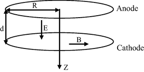
Scheme of the magnetron discharge geometry.
The calculated electron mobility tensor takes the form:
with and , where ν is the electron momentum transfer frequency, is the electron-cyclotron frequency and is mass of the electron.
The mobilities of the ions are calculated using the low electric field Langevin mobility expression (Mc Daniel and Mason, 1973), so we assume that the magnetic field does not affect the ion movement .
Table 1 summarizes the argon gas properties and parameters used in calculation.
is the gas pressure (Torr).
Symbol
Value
d
f
13.56 MHz
ν
μi
Ti
ki
kx
4 Numerical model and boundary conditions
4.1 Numerical model
To resolve the nonlinear coupled equations, we use a method developed by Passchier et al. (Passchier and Goedheer, 1993b; Passchier and Goedheer, 1993a). It is a fully implicit method based on the Scharfetter-Gummel exponential scheme (SG Scheme). The advantage of this scheme is its ability to switch between situations where either the drift component or the diffusion component of the particle flux is dominant (Bogaerts and Gijbels, 1995). The numerical scheme adopted is similar to that described by Scharfetter–Gummel (Scharfetter and Gummel, 1969), which it is also a popular method to overcome the stiffness in the convection–diffusion form of the transport and electron energy equations (Hammond et al., 2002).
The equations (1, 2 and 3) are partial differential equations. We use one dimensional spatial mesh and the FVM for numerical resolution.
The continuity equation and the electron energy equation (electron temperature) have general form of the equation (8). Fluxes of particles and electron energy have general form of the equation (9):
where:
Here is density, is flux and, and are constant and is the source term.
For the electron:
For the ion:
For the electron energy:
After discretization (k for time and j for space), the equations (3) and (8) take the forms:
Flux is discretized by the SG scheme (Scharfetter and Gummel, 1969; Patankar, 1980).
where:
By using the relations (12, 13), we get the forms:
where:
and:
The Eqs. (14) and (15) are a tridiagonal matrix system; they can be solved by Thomas algorithm (Hoffman, 2001).
4.2 Boundary and initial conditions
Table 2 summarizes the boundary conditions and initial conditions used in our calculation.
The anode
The cathode
0
0
0
For initialization data, for electron temperature, we take Te = 1 (Lin and Adomaitis, 1998); for electron and ion densities, we take the expression: (Bouchikhi, 2012; Bouchikhi, 2010).
5 Results and discussion
5.1 Electron and ion densities, electrical potential, electric field and electron temperature (electron energy)
In this sub-section, we present some typical detailed simulation results for argon RF 13.56 MHz magnetron discharges from the numerical modeling based on one dimensional extended fluid model. They are held in the following operating conditions: the voltage at the cathode is set to VRF = 160 V RF forcing amplitude, the gas pressure is 100 mTorr, the magnetic field intensity is B = 30 G, and the inter-electrode distance was set at d = 3 cm. The results will be acceptable for a cylindrical domain and when the dimensions of parallel electrodes are much larger than inter-electrode distance.
Recalling that, in this work, our aim is to calculate electrical properties in an RF magnetron sputtering discharge of argon plasma. In order to validate and test our calculation, we have investigated the evolution of this discharge under the same conditions of simulation as those of Lin and Adomaitis (2001). Then, we compared our results for a null value of magnetic field, B = 0 G, with those obtained by Lin and Adomaitis. The Fig. 2 presents our calculation and those of Lin and Adomaitis inside the reactor; the Fig. 3 presents these results for its right sheath. The Figs. 2 and 3 show that profiles of particles densities between the two calculations are similar.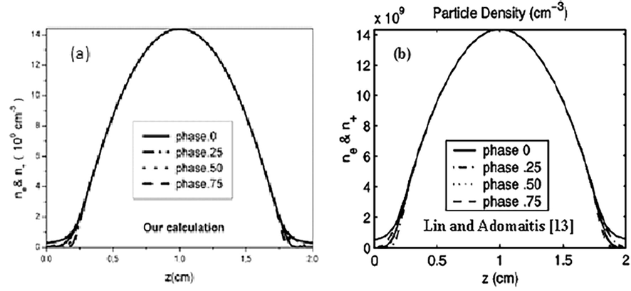
Electron and ionic densities for B = 0 G inside the reactor: (a) Our calculation, (b) Calculation of Lin and Adomaitis (Lin and Adomaitis, 2001).
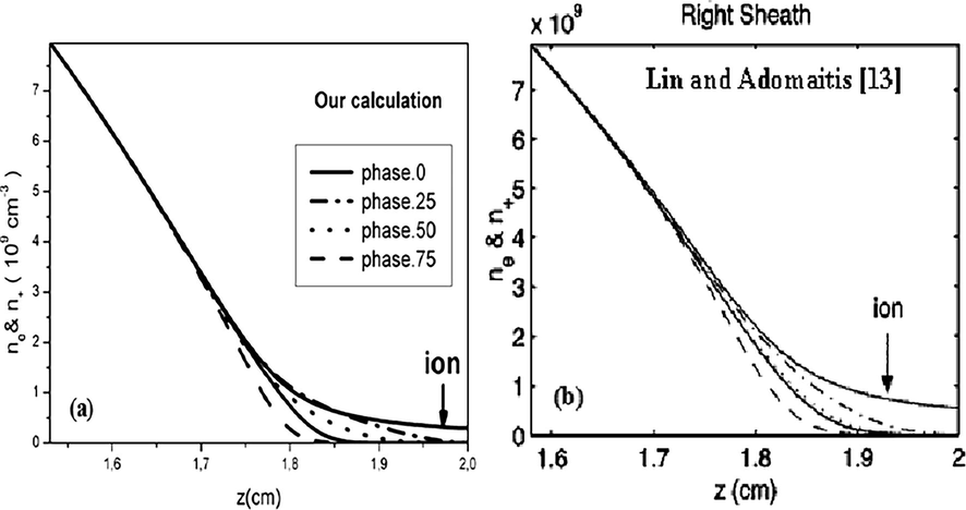
Electron and ionic densities for B = 0 G in the right sheath of the reactor: (a) Our calculation, (b) Calculation of Lin and Adomaitis (Lin and Adomaitis, 2001).
We assume that in argon plasma, there are only electrons and positive ions Ar+. The spatial distributions of electron density, ion density, electrical potential, electric field and electron temperature at different instants of the RF cycle, and for B = 30 G, are shown in the Fig. 4.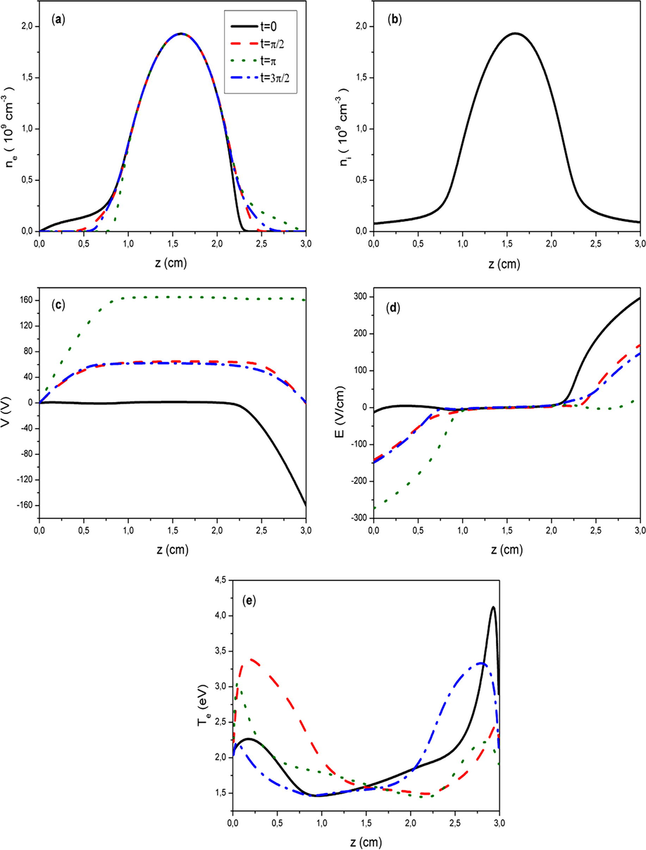
Spatial distributions of plasma parameters, for B = 30 G, at different instants of the RF cycle: (a) electron density, (b) ion density, (c) electrical potential, (d) electric field and (e) electron temperature.
It appears, in Fig. 4a, that the electron density increases gradually as one move away from the powered electrode, then it decreases to the edge of the other electrode. It is the same for the ion density (Fig. 4b). The ion density spatial distribution is essentially not variable during the contraction and expansion of the sheaths due to their low mobility. However, due to higher mobility, the electrons follow the movement of the sheaths at different instants of the RF cycle at 13.56 MHz.
Fig. 4c is spatial distribution of the electrical potential. It shows the quasi neutral property of the plasma in the reactor, the variations are near the sheaths (Lin and Adomaitis, 2001). A ωt = 0, the electrical potential takes a value of 0 Volts on the anode and it increases in absolute value, and then drops near the cathode to take a value of −160 Volts.
Fig. 4d shows the electric field distribution; it is by definition the gradient of the electrical potential. This field is very low in the plasma because of the electrical neutrality whereas it is important in the sheaths due to the oscillatory movement of the electrons with respect to those of the ions.
The electron temperature distribution (Fig. 4e) shows, at ωt = 0, a considerable increasing of the temperature inside the cathode sheath; this increasing is due to the high gradient of electrical potential and the ionization peak occurs in this area. Near the cathode, the electrons are very energetic, Te is about 4,12 eV. In the anode sheath, there is a small drop of the electron temperature: the electrons obtain an additional small quantity of kinetic energy under the effect of the electric field. In the anode Te is about 2,26 eV. At , near the cathode Te is 2,21 eV and near the anode Te is 3,05 eV. So for B not equal zero, the electron energy is larger near the powered electrode.
5.2 The effects of magnetic field intensity (Magnetic field effect)
In this section, we present the effect of the magnetic field intensity in this plasma. The following plasma conditions are: 50 and 100 mTorr for the gas pressure, VRF = 100 V for the applied RF voltage at the cathode 13.56 MHz, 3 cm for the inter-electrode distance and for an instant . The magnetic field intensity is from B = 0 up to 50 G.
Fig. 5 is the plot of spatial distribution of plasma parameters, for gas pressure
= 50 mTorr and for different values of the magnetic field. Fig. 5a and b are for electron and ion densities respectively, Fig. 5c is for electrical potential, Fig. 5d is for electric field and Fig. 5e is for electron temperature. The obtained results show that the charged particle densities, electron temperature, electrical potential and electric field increase generally, when the magnetic field increases.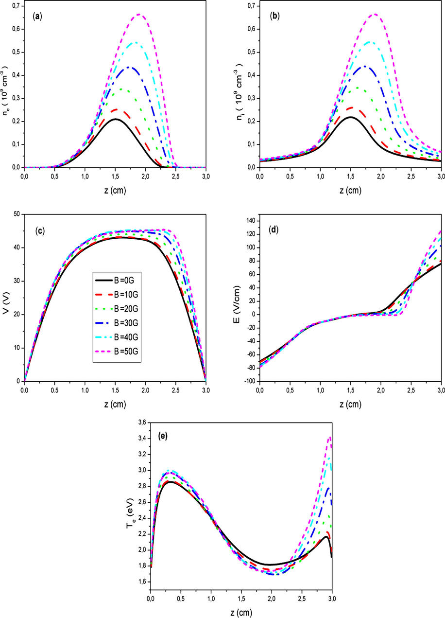
Effect of the magnetic field on the spatial distribution of plasma parameters, for gas pressure
= 50mTorr, and for different values of the magnetic field: (a) electron density, (b) ion density, (c) electrical potential, (d) electric field and (e) electron temperature.
The increase of the charged particle densities can be explained by the effect of the magnetic field, which changes the trajectories of electrons to helical trajectories. This will increase the number of collisions, which prolongs the electrons’ stay inside the plasma reactor, and also to confine them before they are collected at the electrodes, or that they are recombined (Benyoucef, 2011). As a result, the increase also of the density and the flux ion gives automatically an increase of the magnitude of the electric field and the electron temperature in the cathode sheath, thus the efficiency of the spraying.
Fig. 6 presents the variation of the maximum of electron density inside the plasma as a function of the magnetic field for two values of gas pressure 50 and 100 mTorr. With the increase of the magnetic field value, in particular, the results show an increase of the plasma density. For a magnetic field B = 50 G, the increasing of the maximum of electron density are about 68% for
= 50 mTorr and 22% for
= 100 mTorr.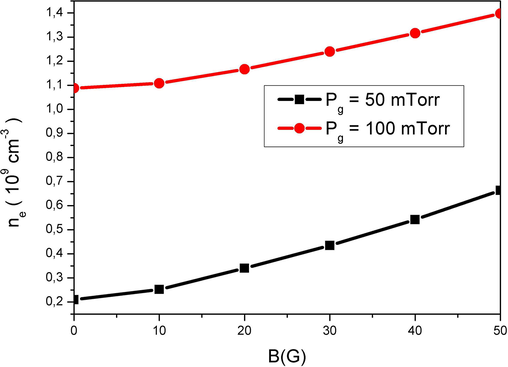
Variation of the maximum of electron density inside the plasma with the magnetic field for 50 and 100 mTorr.
Fig. 7 presents the variations of the maximum of electron temperature in the cathode sheath as a function of the magnetic field for the two values of gas pressure 50 and 100 mTorr. The remarks are the same as those for electronic densities. With the increase of the magnetic field value, the results show an increase of the electron temperature. In the presence of a magnetic field B = 50 G, the increasing of the maximum of electron temperature are about 37% for
= 50 mTorr and 62% for
= 100 mTorr.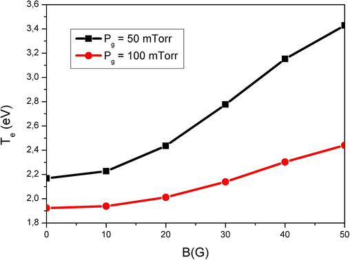
Variation of the maximum of electron temperature in the cathode sheath with the magnetic field for 50 and 100 mTorr.
The obtained results show that the maximum of electron density inside the plasma (Fig. 6) and the maximum of electron temperature in the cathode sheath (Fig. 7) increase in a nonlinear manner with magnetic field. This result has already been emphasized in the literature (Benyoucef et al., 2011; Kostov and Barroso, 2006). For the two values of gas pressure, the increasing of electron density is more important for 50 mTorr and the increasing of the electron temperature is more important for 100 mTorr. The positions corresponding to the relative maximums of electronic densities and electronic temperatures are different. For electronic densities, these positions are very sensitive to the values of the magnetic field.
6 Conclusion
In this paper, we applied a one-dimensional time-dependent fluid model for the simulation of the RF 13,56 MHz magnetron sputtering discharge to determine the electrical properties of an argon plasma. The conditions are those of the deposition of thin films by magnetron sputtering. The electron mobility depends on the magnetic field and the electron diffusivity is assumed to be dependent of electron energy using Einstein's relation. The used model is based on continuity equation and electron temperature equation coupled with Poisson’s equation. The drift–diffusion fluxes are discretized by a FVM; we used the Scharfetter-Gummel exponential scheme and Poisson’s equation. The system of equations is solved by the Thomas algorithm. The proposed model covers comprehensively all regions between the two electrodes and different times of a RF cycle. A comparison has been done with results of Lin and Adomaitis (2001), in null magnetic field, to validate our calculation. The parametric study shows the effect of magnetic field on the electrical properties and electron temperature. The studied electrical properties generally increase by several units. As a perspective, it would be interesting to study the three-dimensional electrical properties as a function of time in a RF Magnetron Sputtering. The plasma may be formed from one or more ionic components. For a detailed view of the effect of the magnetic field on deposition, further study should be made on the calculations of reactivity rates with the surface; these rates are a function of species densities, velocities and mean free paths.
References
- Modélisation numérique des propriétés électriques dans un pulvérisateur cathodique magnétron. Annales de la Faculté des Sciences et Sciences de l’Ingénieur.. 2009;1:24-31.
- [Google Scholar]
- Modélisation particulaire et multidimensionnelle des décharges hors équilibre à basse pression excitées par champs électromagnétiques. Université de Toulouse III – Paul Sabatier; 2011. Ph.DThesis
- Self-consistent particle modeling of radio frequency discharge in Ar/O2mixtures: effects of crossed electric and magnetic fields and partial pressure. J. Appl. Phys.. 2011;109:0833041-0833049.
- [Google Scholar]
- Hybrid Monte Carlo-fluid model of a direct current glow discharge. J. Appl. Phys.. 1995;78:2233-2242.
- [Google Scholar]
- Fluid mode of order two in a 1Dand 2D of a glow discharge. University of Oran; 2010.
- Two-dimensional numerical simulation of the DC glow discharge in the normal mode and with einstein's relation of electron diffusivity. Plasma Sci. Technol.. 2012;14:965-973.
- [Google Scholar]
- On the secondary electron emission in dc magnetron discharge. J. Optoelectron. Adv. Mater.. 2005;7:2465-2469.
- [Google Scholar]
- Analysis of a one-dimensional steady-state magnetron discharge. J. Phys. D. Appl. Phys.. 1997;30:2573-2584.
- [Google Scholar]
- Self-consistent fluid modeling of radio frequency discharges in two dimensions. Appl. Phys. Lett.. 1993;62:3207-3209.
- [Google Scholar]
- A numerical method to simulate radio-frequency plasma discharges. J. Computat. Phys.. 2002;176:402-429.
- [Google Scholar]
- Numerical Methods for Engineers and Scientists. New York: Marcel Dekker; 2001.
- Numerical models of the planar magnetron glow discharges. Contrib. Plasma Phys.. 2004;44:582-588.
- [Google Scholar]
- Numerical simulation of magnetic-fieldenhanced plasma immersion ion implantation in cylindrical geometry. Plasma Sci.. 2006;34:1127.
- [Google Scholar]
- Multidimensional hydrodynamic plasma-wall model for collisional plasma discharges with and without magnetic-field effects. Phys. Plasmas.. 2005;12:0935081-09350810.
- [Google Scholar]
- A global basis function approach DC glow discharge simulation. Phys. Lett. A.. 1998;243:142-150.
- [Google Scholar]
- Simulation and model reduction methods for an RF plasma glow discharge. J. Computat. Phys.. 2001;171:731-752.
- [Google Scholar]
- The Mobility and Diffusion of Ions in Gases. New York: John Wiley & Sons; 1973.
- Moisan, M, Pelleti, J, 2006. Physique des plasmas collisionnels application aux décharges haute frequence, France.
- Argon plasma modeling in a RF magnetron sputtering system. Surf. Coat. Technol. 2004:392-398.
- [Google Scholar]
- A two-dimensional fluid model for an argon RF discharge. J. Appl. Phys.. 1993;74:3744.
- [Google Scholar]
- Relaxation phenomena after laser-induced photodetachment in electronegative RF discharge. J. Appl. Phys.. 1993;73:1073.
- [Google Scholar]
- Numerical Heat Transfer and Fluid Flow. New York: Mc Graw-Hill; 1980.
- Large-signal analysis of a silicon read diode oscillator. IEEE Trans. Electron. Devices.. 1969;16:64.
- [Google Scholar]
- Three-dimensional modelling of the DC glow discharge using the second order fluid model. Przegląd elektrotechniczny. 2013:166-171.
- [Google Scholar]


