

Numerical and experimental study for a modified LPG cooking burner
⁎Corresponding author at: Combustion and Jet Application Research Laboratory (CJARL), Department of Mechanical Engineering, Faculty of Engineering, Ubon Ratchathani University, Warinchamrap, Ubon Ratchathani, 34190, Thailand. Anirut.m@ubu.ac.th (Anirut Matthujak)
-
Received: ,
Accepted: ,
This article was originally published by Elsevier and was migrated to Scientific Scholar after the change of Publisher.
Peer review under responsibility of King Saud University.
Abstract
A new modification of the LPG burner (NB-5) is proposed in this study. The modification combines the advantageous features that originated from three Thai commercial burners: KB-5, S-5, and EB-5. CFD techniques were used to investigate and prove the benefits each burner’s features. Combining features increase the mixing intensity and primary aeration, generates a swirling central flame, reduces heat loss, and increases secondary aeration. These enhancements cause an increase in combustion temperature and flow velocity, which significantly improves the net heat flux of the NB-5. The simulation results indicated that the NB-5 produced the highest average temperature of 929.35 K, and the highest heat flux of 58.01 kW/m2. This leads directly to an enhancement in thermal efficiency. The new modification burner (NB-5) was built and tested experimentally based on CFD results. The NB-5 burner obtained significant improvements in thermal efficiency and a reduction in CO and NOx emissions over the three commercial burners. In comparison with the traditional KB-5 burner, it was found that the NB-5, EB-5, and S-5 burners provided average energy savings of 22.37%, 8.46%, and 1.69%, respectively. This study shows the benefit of utilizing the CFD simulations to assist in designing and modifying LPG burners. This allows manufacturers to design and optimize burners more effectively at a much lower cost than the traditional water boiling tests.
Keywords
LPG burners
New modification burner
CFD
Thermal efficiency

1 Introduction
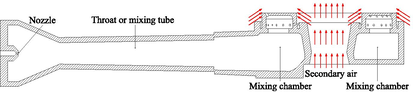
According to the 2030 Agenda for Sustainable Development adopted by the United Nations in 2015 (United Nations, 2015), the innovation of a higher efficiency-domestic LPG burner, which is an important appliance in the household and industrial sector (micro, small and medium-sized enterprises), can help to achieve the 9th Sustainable Development Goal (SDG9). The LPG cooking burner, which is known to be an easy-to-use and low-cost appliance, has been widely used in households in developing countries, including Thailand (Gould and Urpelainen, 2018; Punnarapong et al., 2017; Makmool et al., 2011; Makmool et al., 2007; Lucky and Hossain, 2001). Many researchers have proven that higher efficiency cooking burner use less cooking time and consume less LPG. Past research showed that the thermal efficiency of a burner can be enhanced by adjusting the geometry or arrangement of the nozzle and mixing tube, improving LPG flow characteristics at the burner port, and reducing heat loss with the burner ring.
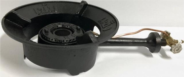
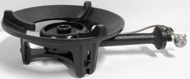
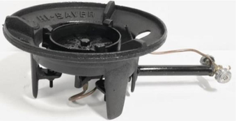
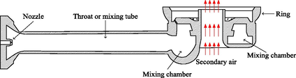
The geometry and arrangement of the nozzle and mixing tube greatly affect the mixing process, the primary aeration, and the burner's thermal efficiency (Datta et al., 2021; Dahiya et al., 2016). One of the most popular LPG burners used in Thailand households is the Kutsura Burner-5 (KB-5), as shown in Table 1 (Suwansu et al., 2013). Although the thermal efficiency of the KB-5 was found to be relatively low (around 35%), the horizontal arrangement of the nozzle and mixing tube helps reduce combustion smut. A recent energy-saving burner (EB-5) was developed and introduced to the market in Thailand. In comparison with the KB-5, the EB-5 had a higher thermal efficiency at around 45% (Wichangarm et al., 2020). However, a vertical arrangement of the nozzle and the short mixing tube of the EB-5 gave a larger amount of combustion smut beneath the burner cap. The geometrical differences between the EB-5 and the KB-5 include the mixing tube, the opening for secondary air, the combustion chamber, and the burner ring.
| KB-5 | S-5 | EB-5 |
|---|---|---|
|
||
|
|
|
|
||
|
|
|
|
|
|
One well-known technique to improve the LPG flow at the burner port is having a swirling flow flame. The swirling flame, as a result of rotation flow, was found to enhance the mixing process between the hot gas and the surrounding air and which prolongs the residence time (Tamir et al., 1989; Sapra and Chander, 2021; Sung et al., 2017; Kotb and Sadd, 2018; Singh et al., 2012; Zhen et al., 2011; Zhen et al., 2010; Luo et al., 2010; Jugjai et al., 2001; Matthujak et al., 2021). The following advantages resulted from the swirling flow flame; 1) enhancement of air–fuel mixing due to prolonged mixing time of the fuel and air, 2) improvement in heat transfer due to a prolonged residence time during heat transfer and an increased heat transfer area between the flame and the vessel surface, and 3) enhancement in combustion due to the increase of the entrained secondary air. The very first and well know invented swirl burner was conducted by Tamir et al. (1989). A swirling central flame was produced by using the burner ports with an inclined angle (β) of 26° and a specified swirl angle (α) of 15°. Improvement in thermal efficiency over the conventional burner was 6%. Later, modified swirl burners, based on the work done by Tamir et al. (1989), were built and tested by Jugjai et al. (2001). The enhancement in thermal efficiencies of co-swirling burners, a counter-swirling burner, and a conventional domestic burner were experimentally investigated by Kotb and Sadd (2018). Lower CO emissions and higher thermal efficiency were found with the co-swirling and counter-swirling burners in comparison with the base burner.
Due to unexpected diffuse heat loss out of the heating zone, significant heat loss was found using LPG burners without a burner ring (Makmool et al., 2011; Makmool et al., 2007; Suwansri et al., 2013; Kotb and Saad, 2018). This heat loss lowers thermal efficiency, especially when the LPG-released pressure is high (Wichangarm et al., 2020; Jugjai et al., 2001; Mishra et al., 2015; Panigrahy et al., 2016; Matthujak et al., 2021). Burner rings enhance the thermal efficiency of LPG burners by forcing the flame to flow densely beneath the vessel, thus reducing heat loss to the surroundings (Wichangarm et al., 2020; Boggavarapu et al., 2014; Matthujak et al., 2021). Therefore, burner rings used with the LPG burners should be capable of the following; (1) reducing the heat loss to the surrounding air, (2) holding and forcing the combustion flame to reach the vessel, and (3) allowing a sufficient amount of secondary airflow into the combustion zone.
Improvements in LPG burners in the past were primarily made based on experimental methods. However, some past studies used CFD to assist in the study and design of LPG burners (Datta et al., 2021; Wichangarm et al., 2020; Boggavarapu et al., 2014; Matthujak et al., 2021; Deymi-Dashtebayaz et al., 2022; Deymi-Dashtebayaz et al. 2023).
In 2020, an energy-saving (EB-5) was investigated using CFD (Wichangarm et al., 2020). The CFD results for the outlet gas velocity and hot gas temperature were verified by the measurement results. The simulated results helped to clarify the flow and heat transfer mechanisms that affect the thermal efficiency of the EB-5. Moreover, a method to evaluate thermal efficiency from the CFD steady-state model was proposed using a defined boiling efficiency (ηb).
The swirl-energy saving burner (SEB-5), a modified version of the EB-5, was invented to induce a swirling central flame (Matthujak et al., 2021). Burner ports of the SEB are aligned with an inclined angle of 50° and a swirl angle of 15. The flow inside the SEB and the EB were numerically investigated. The CFD results were used to calculate boiling efficiencies and heat conversion efficiencies. The results confirmed that the swirling flow does increase the maximum combustion temperature and the net heat flux into the vessel, directly enhancing the heat conversion efficiency and thus increasing the thermal efficiency. The heat conversion efficiency of the SEB was found to be 3.44% greater than the EB's. The experiments also showed that the thermal efficiency of the SEB was 2.75% higher than the EB's.
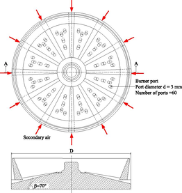
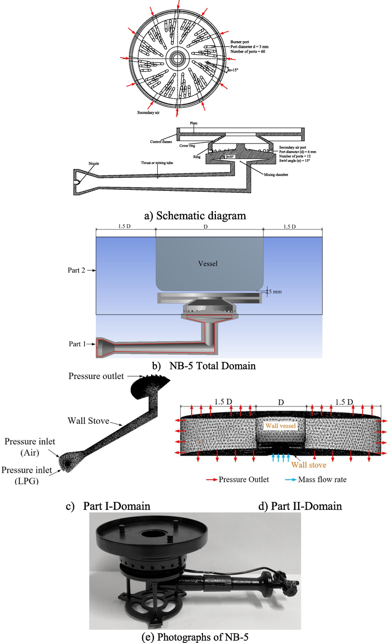
According to the second law analysis, the thermal efficiency of these LPG cooking burners can be further improved. With improvement in thermal efficiency, the energy consumption and emissions can be reduced. In the past, most of the cooking burner studies attempted to improve burner efficiency through experiments. Recently, the numerical technique has been applied to burner studies. The main objective of the current study is to apply the knowledge and concepts obtained from our previous studies (Wichangarm et al., 2020; Matthujak et al., 2021) to design a new high-efficiency LPG burner (NB-5). Three Thailand-domestic commercial burners, namely KB-5, S-5, and EB-5, were examined numerically for the first part. Table 1 illustrates the characteristics of the three commercial burners used in this study. The two significant differences for the burners are the mixing tubes and the burner heads. As can be seen, both the KB-5 and the S-5 burners have a horizontally arranged nozzle and a long mixing tube. In contrast, the EB-5 has a vertically arranged nozzle and a short mixing tube. Also, the KB-5 and S-5 use a burner head with the burner ports aligned on the four circumferences. In contrast, the EB-5 has a burner ring and a burner head with burner ports that are uniformly distributed along the radius of the burner head. The NB-5 was designed by applying the advantages of the features from the KB-5 and the S-5 (the horizontal arrangement of the nozzle and the long mixing tube) and from the EB-5 (the burner head and burner ring). The advantages of these burners, especially for those specific features, are explained using the presented numerical results. The NB-5 thus was built (based on the CFD geometry) and tested experimentally.
2 Numerical simulation
2.1 Numerical setup of the three commercial LPG burners (KB-5, S-5, and EB-5)
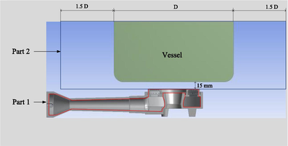
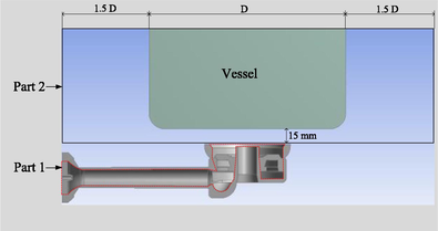
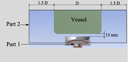
Commercial CFD software, ANSYS FLUENT version 15.0, was used as a tool to investigate the flow and combustion inside the target burners. The same numerical procedure used in our previous publication (Matthujak et al., 2021) was applied to this study. In addition, steady-state 3D models were applied with a fixed temperature at the outer surface of the pot to simplify the problem with a certain degree of compromised accuracy. The numerical domain of each burner was split into two parts (Part I and Part II), as shown in Table 2, to reduce the complexity of the numerical scheme. Also, the boundary conditions of Part I and Part II are indicated in Table 2.
| KB-5 | S-5 | EB-5 |
|---|---|---|
|
|
|
| Part I-Domain | ||
| Tetrahedral mesh of 1,404,415 elements | Tetrahedral mesh of 1,632,136 elements | Tetrahedral mesh of 1,539,082 elements |
|
|
|
| Part II-Domain | ||
| Tetrahedral mesh of 1,497,671 elements | Tetrahedral mesh of 1,179,550 elements | Tetrahedral mesh of 1,391,880 elements |
|
|
|
Part I of the model was the non-combustion model (cold test), where LPG and air enter the inlets, mix inside the mixing tube, and leave the outlet (burner port) without a reaction. Tetrahedral elements were constructed for Part I. The number of elements for Part I of KB-5, S-5, and EB-5 is given in Table 2. The walls of the burner cap and the ring were set with non-slip and adiabatic wall conditions. A pressure inlet condition of 1 atm and 300 K was set at the fuel and air inlets. A pressure outlet condition was set at the top of the burner ports. The RNG k-ε turbulence model, which is an appropriate model for a wide range of speeds and Reynolds numbers (Karadimou et al., 2019; Matthujak et al., 2021), was set to determine the turbulence characteristics. The species transport model was also enabled to simulate air–fuel mixing. The LPG contained 70% propane and 30% butane by weight. The simulations also include buoyancy and gravitational effects. The model setup and the boundary conditions for this cold test simulation are listed in Table 3. The solutions obtained from this part, including the mixing mass flow rate and species mass fractions (propane, butane, oxygen, and nitrogen), would later be used as input data for Part II.
| Boundary Conditions and Models | Selected Values |
|---|---|
| Inlet Boundary Conditions | Air Inlet Gauge Pressure = 0 Pa |
| LPG Inlet Gauge Pressure = 20,000 Pa | |
| Outlet Boundary Condition | Pressure Outlet(Air Outlet Gauge Pressure = 0 Pa) |
| Solver Type | Pressure-based |
| Time | Steady state |
| Near-wall Treatment Method | Standard Wall Function |
| Turbulence Model | RNG k-ε Model |
| Other Model(s) | Species Transport |
| Propane: Butane | 70: 30 |
| Operating Condition | Operating Pressure = 1 atm |
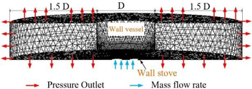
Part II was the combustion model (hot test simulation), where the combustion reaction and heat transfer models were set. The domain spanned from the top of the burner head to the zone adjacent to the pot surface. To minimize the effect of the physical free boundary condition, the Part II-domain was extended to four times the pot’s diameter, as shown in Table 2. The domain was discretized with a tetrahedral mesh. The number of elements for Part II of KB-5, S-5, and EB-5 are given in Table 2. Results of outlet mass flow rate and species mass fractions derived from Part I (at each of the LPG inlet pressure) were used as input for the mass flow inlet condition of Part II. The heat transfer in consideration was mainly from heat convection due to the hot flue gases, i.e., combustion products and the heat radiation from the flame. The standard k-ε turbulence model, an appropriate model for combustion (Gaukhar et al., 2019; Boggavarapu et al., 2014) and high Reynolds number flow (Matthujak et al., 2021), was applied. An eddy dissipation combustion model was also selected. Due to the significant difference in combustion temperatures, the Discrete Ordinates (DO) radiation model was used as reported by Boggavarapu et al. (2014). The convergence criterion for the computational residuals was set at 10-6. Table 4 summarizes the model setup and boundary conditions for Part II.
| Boundary Conditions and Models | Selected Values |
|---|---|
| Inlet Boundary Conditions | Mass Flow Inlet (from Part I) |
| Mass Fractions of C3H8, C4H10, N2,and O2 (from Part I) | |
| Air Inlet Gauge Pressure = 0 Pa | |
| Outlet Boundary Condition | Pressure Outlet(Air Outlet Gauge Pressure = 0 Pa) |
| Solver Type | Pressure-based |
| Time | Steady state |
| Near-wall Treatment Method | None |
| Turbulence Model | Standard k-ε Model |
| Radiation Model | Discrete Ordinates (DO) Radiation Model |
| Combustion Model | Eddy Dissipation Model |
| Operating Condition | Operating Pressure = 1 atm |
The CFD calculations were considered converged when the two following criteria were met. The first condition was that the computational residuals were lower than 10-6. The other required that the difference between the total mass fluxes entering and leaving the domain was smaller than 10−7 so that the principle of mass conservation was sufficiently observed. In addition, the validations against the experimental data for both parts of the three burners were conducted to ensure that the model was sufficiently accurate. The mixing flow velocity distribution was validated against the experimental measurements for Part I. The flow velocities were measured using hot-wire anemometers (Testo-435 model) with an uncertainty of ± 0.03 m/s (±5% error of reading). It was found that the velocity values from the CFD simulation and the experimental data agreed with a maximum error of 6.98%.
For Part II, the temperature result from the simulation was validated against the experimental data. The K-type thermocouples with a data logger with an uncertainty of ± 1.1 °C (±0.4% error of reading) were used to measure the hot gas temperature. The maximum discrepancy was found to be less than 5.75%.
Moreover, mesh independence tests for all burners and for both Part I and Part II were performed. Different mesh resolutions and their errors are illustrated in Table 5.
| Mesh1 | Mesh2 | Mesh3* | Mesh4 | Mesh5 | ||||||
|---|---|---|---|---|---|---|---|---|---|---|
| elements | %error | elements | %error | elements | %error | elements | %error | elements | %error | |
| Part I | ||||||||||
| KB-5 | 983,812 | 5.98 | 1,132,549 | 5.42 | 1,404,415 | 5.38 | 2,275,112 | 5.34 | 2,640,421 | 5.31 |
| S-5 | 981,732 | 5.82 | 1,250,721 | 5.48 | 1,632,136 | 5.11 | 1,905,273 | 4.98 | 2,455,121 | 4.92 |
| EB-5 | 885,120 | 6.01 | 1,252,781 | 5.91 | 1,539,082 | 5.76 | 1,971,329 | 5.71 | 2,105,223 | 5.67 |
| NB-5 | 792,134 | 6.00 | 1,252,337 | 5.83 | 1,714,398 | 5.73 | 1,958,360 | 5.70 | 2,358,331 | 5.68 |
| Part II | ||||||||||
| KB-5 | 825,001 | 6.11 | 1,100,874 | 5.92 | 1,497,672 | 5.54 | 1,920,741 | 5.52 | 2,370,110 | 5.49 |
| S-5 | 758,121 | 5.97 | 921,785 | 5.61 | 1,079,550 | 5.43 | 1,372,590 | 5.40 | 1,740,551 | 5.38 |
| EB-5 | 625,112 | 5.99 | 851,640 | 5.76 | 1,391,880 | 5.53 | 1,797,217 | 5.50 | 1,987,442 | 5.48 |
| NB-5 | 801,911 | 5.97 | 942,134 | 5.40 | 1,527,334 | 5.11 | 1,825,717 | 5.08 | 1,920,113 | 4.95 |
Remark * is the selected mesh elements to be used.
2.2 Numerical setup of the modified LPG burners (NB-5)
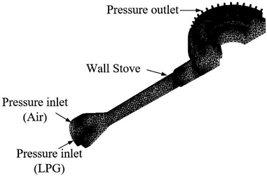
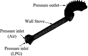
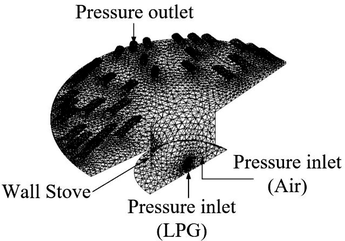
The NB-5 was designed by applying the advantageous features from the KB-5 and S-5 (horizontal arrangement of the nozzle and mixing tube) and the EB-5 (burner head and burner ring), as shown in Fig. 1. Moreover, the swirl central flame technique, proven to enhance burner performance (Mathujak et al. (2021)), was applied to the design of the NB-5. The concepts of modification are summarized as follows.
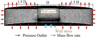
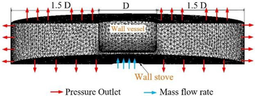
- Numerical Domain and mesh information for a modified burner (NB-5).
Concepts of modification
-
Use a combination of long horizontal and short vertical mixing tubes (L-shaped) to provide a higher turbulence intensity and, hence, a better mixing process and primary aeration.
-
Combine an inclined and swirl angle for the burner ports to produce a swirling central flame and to prolong the residence time of heat transfer.
-
Introduce a burner ring with a convergent-divergent shape to control the high-temperature zone.
-
Drill secondary aeration holes with a swirl angle at the burner ring to increase the secondary air flow rate.
We applied the same numerical procedure as described in section 2.1. The numerical domain and the mesh information for the NB-5 (for both Part I and Part II) are illustrated in Fig. 1. CFD results obtained from both Part I and Part II of the NB-5 are compared to the other burners, as shown in the following section.
2.3 CFD results
2.3.1 Results of Part I
This section presents the differences between simulated flow fields and velocity distributions for the KB-5, S-5, EB-5, and NB-5 burners (Fig. 2). Also, two important results obtained from Part I: the average intensity (Iav) and the primary aeration (%PA) were tabulated. As shown in Table 6, the mixing tubes of KB-5 and S-5 are long horizontal tubes, while the EB-5 and SEB-5 (Matthujak et al., 2021) have short vertical tubes.
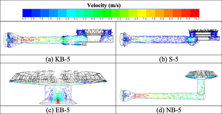
- The velocity distributions at 0.2 bar (midplane view).
| Parameter | Bar | KB-5 | S-5 | EB-5 | NB-5 | %increase of NB-5 over KB-5 | %increase of NB-5 over S-5 | %increase of NB-5 over EB-5 |
|---|---|---|---|---|---|---|---|---|
| Iav(%) | 0.2 | 70.24 | 73.91 | 77.45 | 83.23 | 18.49 | 12.61 | 7.46 |
| 0.4 | 78.76 | 82.43 | 85.97 | 91.75 | 16.49 | 11.31 | 6.72 | |
| 0.6 | 87.49 | 91.16 | 94.7 | 100.48 | 14.85 | 10.22 | 6.1 | |
| 0.8 | 91.63 | 95.3 | 98.84 | 104.62 | 14.18 | 9.78 | 5.85 | |
| 1 | 101.12 | 104.79 | 108.33 | 114.11 | 12.85 | 8.89 | 5.34 | |
| %PA | 0.2 | 58.45 | 59.76 | 72.5 | 75.73 | 29.56 | 26.72 | 4.46 |
| 0.4 | 60.26 | 61.92 | 73.82 | 76.14 | 26.35 | 22.97 | 3.14 | |
| 0.6 | 61.87 | 62.4 | 75.59 | 77.64 | 25.49 | 24.42 | 2.71 | |
| 0.8 | 62.92 | 63.19 | 77.92 | 79.22 | 25.91 | 25.37 | 1.67 | |
| 1 | 63.81 | 64.6 | 79.52 | 81.76 | 28.13 | 26.56 | 2.82 |
The primary aeration is calculated using CFD information. The equation obtained for the percentage of primary aeration is shown in Eq. (1).
R = entrainment ratio obtain from CFD
(A/F)stoi. = theoretical air–fuel ratio
Turbulence intensity, which is referred to as turbulence level, is often used to measure mixing quality. The higher turbulence intensity, therefore, indicated better mixing intensity. From Table 6, it can be observed that the NB-5 mixing tube combined both horizontal and vertical mixing with an L-shape mixing tube that provided a higher average turbulence intensity and higher primary aeration than the other mixing tubes. The comparative results obtained from this part indicate a better mixing process of air and LPG for NB-5 due to higher turbulent intensity and primary aeration. Hence, the mixing quality between LPG and air for the NB-5 is better for all LPG pressures.
2.3.2 Results of Part II
This section presents the differences between the simulated combustion temperature results and hot gas velocity distributions for the KB-5, S-5, EB-5, and NB-5 burners.
Temperature distributions and velocity vector fields on the midplane of the Part II-domain for the three commercial burners and the NB-5 at the LPG pressure of 0.2 bar are illustrated in Fig. 3. At the other simulated LPG pressures, selected flow quantities are reported in Table 7.
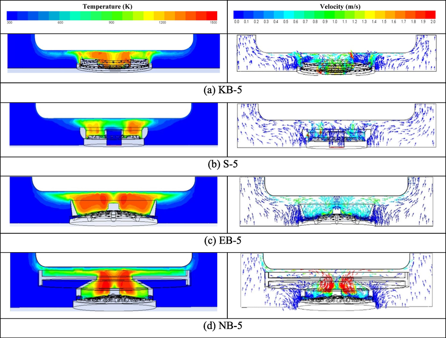
- The temperature and the velocity distributions at 0.2 bar (midplane view).
| Parameter | Bar | KB-5 | S-5 | EB-5 | NB-5 | %increase of NB-5 over KB-5 | %increase of NB-5 over S-5 | %increase of NB-5 overEB-5 |
|---|---|---|---|---|---|---|---|---|
| Iav (%) | 0.2 | 36.79 | 38.72 | 42.02 | 47.8 | 29.93 | 23.45 | 13.8 |
| 0.4 | 45.31 | 46.53 | 51.53 | 59.13 | 30.50 | 27.08 | 14.7 | |
| 0.6 | 54.04 | 55.98 | 60.54 | 68.81 | 27.33 | 22.92 | 13.7 | |
| 0.8 | 58.18 | 59.67 | 64.09 | 74.37 | 27.83 | 24.64 | 16 | |
| 1 | 67.67 | 68.57 | 73.23 | 76.96 | 13.73 | 12.24 | 5.1 | |
| Tav (K) | 0.2 | 762.13 | 786.7 | 810.82 | 917.67 | 20.41 | 16.65 | 13.2 |
| 0.4 | 765.73 | 819.21 | 815.56 | 912.72 | 19.20 | 11.41 | 11.9 | |
| 0.6 | 770.43 | 830.94 | 821.43 | 923.98 | 19.93 | 11.20 | 12.5 | |
| 0.8 | 774.28 | 835.8 | 824.28 | 926.37 | 19.64 | 10.84 | 12.4 | |
| 1 | 778.51 | 843.84 | 829.05 | 929.35 | 19.38 | 10.13 | 12.1 | |
| Vav (m/s) | 0.2 | 0.27 | 0.34 | 0.36 | 0.42 | 55.56 | 23.53 | 16.7 |
| 0.4 | 0.4 | 0.46 | 0.53 | 0.62 | 55.00 | 34.78 | 17 | |
| 0.6 | 0.49 | 0.57 | 0.61 | 0.72 | 46.94 | 26.32 | 18 | |
| 0.8 | 0.59 | 0.65 | 0.74 | 0.81 | 37.29 | 24.62 | 9.5 | |
| 1 | 0.65 | 0.73 | 0.83 | 0.86 | 32.31 | 17.81 | 3.6 | |
| Heat Flux (kW/m2) | 0.2 | 20.65 | 21.55 | 24.96 | 30.05 | 45.52 | 39.44 | 20.4 |
| 0.4 | 29.7 | 32.98 | 35.3 | 45.24 | 52.32 | 37.17 | 28.2 | |
| 0.6 | 34.57 | 38.47 | 40.22 | 52.5 | 51.87 | 36.47 | 30.5 | |
| 0.8 | 38.07 | 40.02 | 43.43 | 58.01 | 52.38 | 44.95 | 33.6 | |
| 1 | 41.05 | 42.38 | 45.69 | 61.63 | 50.13 | 45.42 | 34.9 |
The results showed that the combustion flames were forced to remain inside the ring region due to the presence of the burner ring for the S-5, EB-5, and NB-5. As a result, their high-temperature zones outside the ring region were relatively thin and close to the solid surfaces. However, the burner ring of the S-5 is shorter than that of the EB-5. Hence, its high-temperature zone outside the ring region was relatively thick and farther from the solid surface compared to the EB-5. As a result, the high-temperature zone of the NB-5 reached closer to the solid surface of the pot with the help of the convergent-divergent nozzle ring (Fig. 3d). The burner ring enhances the heat transfer by reducing the convective heat loss (the major loss for open combustion) and focusses the hot gas flow closer to the target solid surface. Therefore, a convergent-divergent-shaped burner ring (Fig. 3d) creates a narrower combustion zone to produce a higher average temperature (Tav), as shown in Table 7.
Table 7 compares selected flow quantities between the NB-5 burner with three commercial burners. An increase in LPG pressure causes increases in the average turbulence intensity, average combustion temperature, average hot gas velocity, and total heat flux gained at the pot surface. It also shows the improvements of the NB-5 over the three commercial burners. For example, at an LPG pressure of 1 bar, the average turbulence intensity (Iav), average combustion temperature (Tav), average hot gas velocity (Vav), and total heat flux gained at the pot surface of the NB-5 were, respectively, 13.73%, 19.38%, 32.31%, and 50.13% higher than those of the KB-5. At the same pressure, the NB-5 provided improvements in the average turbulence intensity (Iav), average combustion temperature (Tav), average hot gas velocity (Vav), and total heat flux gained at the pot surface over the S-5 by 12.24%, 10.13%, 17.81%, and 45.42%, respectively. The improvements of the NB-5 over the EB-5 was found to be 5.1%, 12.1%, 3.6%, and 34.9% for the average turbulence intensity, average combustion temperature, average hot gas velocity, and total heat flux, respectively. The improvement of the NB-5 over the other burners is mainly due to the advantages in the swirl flow. The swirling flame utilizes rotational flow motion to enhance the mixing of the hot gas with the surrounding air, increasing the heat transfer area, and prolong the residence time (Tamir et al., 1989; Wichangarm et al., 2020; Matthujak et al., 2021). The swirling flow increases the turbulence intensity, amount of entrained secondary air, maximum combustion temperature, and maximum velocity. Thus, the swirl flow can enhance combustion and heat transfer to the target vessel.
Therefore, the conclusion drawn from this section is that the modified burner (NB-5) provided better results that could enhance its thermal efficiency compared to the other burners. To prove this, a prototype of the NB-5 was built (based on the CFD geometry), as shown in Fig. 1e). Experiment results of thermal efficiency for the NB-5 compared to the other burners confirmed the advantages of the NB-5 as described in the next section.
3 Thermal efficiency test
The thermal efficiencies of the burners were evaluated using the water boiling test (DIN EN 203–2 standard) as conducted on previous studies (Wichangarm et al., 2020; Matthujak et al., 2021). This section shows the results for thermal efficiency, calculated energy saving, and emissions for the KB-5, S-5, EB-5, and NB-5. Moreover, the experimental results of the SEB-5 (the swirl energy-saving burner) obtained from previous work by Matthujak et al. (2021) are also compared. Finally, the energy saving percentage is calculated based on the savings over the traditional KB-5 burner, as illustrated in Eq. (2).
ηth: the thermal efficiency of the considered burner
ηth,KB-5: the thermal efficiency of KB-5 burner
Fig. 4 compares the thermal efficiency and CO and NOx emission of each burner obtained from the boiling test based on DIN EN 203-2 standard at various LPG released pressures. As one intuitively expects, a higher LPG pressure results in higher net heat flux. In contrast, a rise in LPG pressure leads to an increment in heat loss. Consequently, the thermal efficiency decreases as the LPG pressure increases, as shown in Fig. 4(a). The decrease in thermal efficiency with an increase in LPG pressure is a well-known behavior of LPG burners (Wichangarm et al., 2020; Jugjai et al., 2001; Mishra et al., 2015; Panigrahy et al., 2016; Matthujak et al., 2021). The NB-5 shows the highest thermal efficiency, followed by the SEB-5, EB-5, S-5, and KB-5 for all pressure levels, according to Fig. 4(a). The maximum thermal efficiency obtained at an LPG pressure of 0.2 bar for the NB-5, SEB-5, EB-5, S-5, and KB-5 burners is 52.67%, 50.034%, 46.08%, 41.33%, and 38.21%, respectively. The average thermal efficiency of the NB-5, SEB-5, EB-5, S-5, and KB-5 burners is 49.22%, 44.49%, 41.74%, 38.86%, and 35.85% at an LPG pressure range of 0.2–1.0 bar, respectively. Compared with KB-5 as the benchmark burner, the maximum energy-saving of NB-5, SEB-5, EB-5, and S-5 burners is 27.45%, 23.63%, 17.08%, and 7.55%, respectively. The average energy-saving of NB-5, SEB-5, EB-5, and S-5 burners is 22.37%, 14.12%, 8.46%, and 1.69%, respectively.
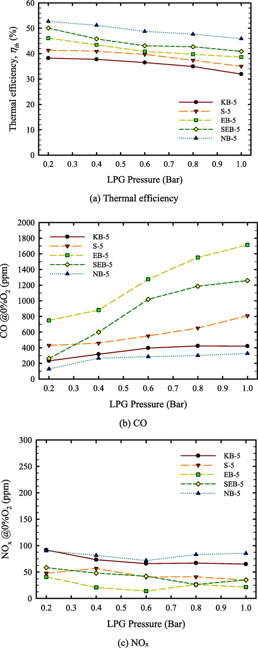
- Comparison of thermal efficiency and CO and NOx emission of each burner.
The CO and NOx emission of each burner was also measured and reported in Fig. 4(b) and Fig. 4(c), respectively. From Fig. 4(b), the CO of all burners increased as the LPG pressure decreased, corresponding to the decrease in thermal efficiency. This is because of the quenching effect, a normal behavior of LPG cooking burners explained by many researchers (Wichangarm et al., 2020; Jugjai et al., 2001; Mishra et al., 2015). At all LPG pressures, the CO emission of the burners with a long horizontal mixing tube (NB-5, S-5, and KB-5) are lower than that of the burners without it (EB-5 and SEB-5). It is well known that suitable residual time in the mixing process is necessary for complete combustion. Therefore, the long horizontal mixing tube helps to extend the residual time in the mixing process. As proven through CFD, the combination of a long horizontal and a short vertical mixing tube (L-shape mixing tube), used for the NB-5, helps to extend the residual time and generate a higher turbulence intensity. This results in a better mixing process, more complete combustion, and less CO emission. However, the CO emission of all burners is lower than 2000 ppm, which is lower than the maximum CO level based on TIS 2312–2549 (Thai Industrial Standard) (Industrial Standards (Thai Industrial Standard, TIS) TIS. 2312-2549). Since the LPG domestic burner provides a lower combustion temperature of 1500 K, the thermal NOx being the major NOx in the combustion process, is not generated. Thus, the NOx of each burner was very low, e.g., lower than 120 ppm, as shown in Fig. 4(c).
It has been proven in this section that the NB-5, designed based on the CFD results, produces a significant enhancement in thermal efficiency and a reduction of CO emission.
4 Concluding remarks
The present study proposes a new modification of the LPG burner, the NB-5. The modification combines advantageous features originating from the KB-5, the S-5, and the EB-5 burners. CFD techniques were used to investigate and prove the benefits of the features mentioned earlier. The comparative results obtained from Part I (cold test simulation) indicate a better mixing process of air and LPG for NB-5 due to higher turbulence intensity and primary aeration. For Part II, the simulated results, including the (1) average turbulence intensity, (2) average temperature, (3) average velocity, and (4) total heat flux obtained from the NB-5 burner were significantly higher than those found for the other three burners. The simulations showed that combining the foresaid features generates a swirling central flame that can reduce heat loss by controlling the higher temperature zone inside the ring region and increases primary and secondary aeration. This enhances the turbulence intensity and the entrained secondary air flow rate. This causes an increase in the combustion temperature and the flow velocity, significantly improving the net heat flux of the NB-5. From the simulation results, the NB-5 produced the highest average temperature of 929.35 K and the highest heat flux of 58.01 kW/m2. Finally, this leads directly to an enhancement in thermal efficiency.
To prove the CFD results, the NB-5 was built and tested experimentally. As expected, significant improvements in thermal efficiency and reduction in CO emissions were found for the NB-5 versus the other three commercial burners. The average energy-saving over the traditional KB-5 of NB-5, SEB-5, EB-5, and S-5 burners is 22.37%, 14.12%, 8.46%, and 1.69%, respectively. To conclude, this study successfully utilized CFD techniques to assist in designing and modifying LPG burners. There currently is a Thai patent protection application in process for the resulting invented burner (NB-5).
Acknowledgment
This paper was financially supported by Ubon Ratchathani University (Fundamental Fund 2564)
Declaration of Competing Interest
The authors declare that they have no known competing financial interests or personal relationships that could have appeared to influence the work reported in this paper.
References
- Thermal Efficiency of LPG and PNG-fired burners: experimental and numerical studies. Fuel. 2014;116:709-715.
- [Google Scholar]
- Improvement of the domestic LPG cooking stoves: a review. Indian J. Sci. Technol.. 2016;9(S1)
- [CrossRef] [Google Scholar]
- Design, development, and technological advancements in gas burners for domestic cook stoves: a review. Trans. Indian Natl. Acad. Eng.. 2021;6:569-593.
- [Google Scholar]
- Optimum swirl angle of natural gas combustion in domestic cooker burner with various output port. Proc. Inst. Mech. Eng. C J. Mech. Eng. Sci.. 2022;236(24):11571-11585.
- [Google Scholar]
- Numerical and experimental analyses of a novel natural gas cooking burner with the aim of improving energy efficiency and reducing environmental pollution. Energy Part E. 2023;263:126020 ISSN 0360–5442
- [Google Scholar]
- Three-dimensional modelling of gas-air mixture combustion process. J. King Saud Univ. - Sci.. 2019;31:1326-1338.
- [Google Scholar]
- LPG as a clean cooking fuel: adoption, use, and impact in rural India. Energy Policy. 2018;122:395-408.
- [Google Scholar]
- Industrial Standards (Thai Industrial Standard, TIS) TIS. 2312-2549. Household cooking stoves using liquefied petroleum gas. Vol.126, (episode 40).
- Experimental study on high efficiency heat-recirculating gas burners based on the porous medium technology. Asian J. Energy Environ. 2001;3–4:169-198.
- [Google Scholar]
- Mathematical modelling and numerical simulation of two-phase gas-liquid flows in stirred-tank reactors. J. King Saud Univ. - Sci.. 2019;31:33-41.
- [Google Scholar]
- Case study for co and counter swirling domestic burner. Case Stud. Therm. Eng.. 2018;11:98-104.
- [Google Scholar]
- Efficiency study of Bangladeshi cook-stoves with an emphasis on gas cookstoves. Energy. 2001;26:221-237.
- [Google Scholar]
- Premixed flame impingement heat transfer with induced swirl. Int. J. Heat Mass Transfer. 2010;53:4333-4336.
- [Google Scholar]
- Performance and analysis by particle image velocimetry (PIV) of cooker-top burners in Thailand. Energy. 2007;32:1986-1995.
- [Google Scholar]
- Laser-based investigations of flow fields and OH distributions in impinging flames of domestic cooker-top burners. Fuel. 2011;90:1024-1035.
- [Google Scholar]
- Numerical investigation on the influences of swirling flow to thermal efficiency enhancement of an LPG-energy saving burner. Case Stud. Therm. Eng.. 2021;28:101466
- [Google Scholar]
- Performance characterization of a medium-scale liquefied petroleum gas cooking stove with a two-layer porous radiant burner. Appl. Therm. Eng.. 2015;89:44-50.
- [Google Scholar]
- Numerical and experimental analyses of LPG (liquefied petroleum gas) combustion in a domestic cooking stove with a porous radiant burner. Energy. 2016;95:404-414.
- [Google Scholar]
- Performance evaluation of premixed burner fueled with biomass derived producer gas. Case Stud. Therm. Eng.. 2017;9:40-46. October 2016
- [Google Scholar]
- Effect of enclosure on heat transfer characteristics of dual swirlingflame impinging on a flat surface. Heat Mass Transf.. 2021;57:1011-1023.
- [Google Scholar]
- Heat transfer characteristics of natural gas/air swirling flame impinging on a flat surface. Exp. Therm Fluid Sci.. 2012;41:165-176.
- [Google Scholar]
- Generation mechanisms of tube vortex in methane-assisted pulverized coal swirling flames. Fuel Process. Technol.. 2017;156:228-234.
- [Google Scholar]
- Suwansri, S., Moran, J.C., Aggarangsi, P., Tippayawong, N., Bunkham, A., Rerkkriangkrai, P., 2013. Commercial Stove Conversion to Biomethane in Thailand. In: Proceeding of the 4th TSME International Conference on Mechanical Engineering (TSME-ICOME 4).
- Performance characteristics of a gas burner with a swirling central flame. Energy. 1989;14(7):373-382.
- [Google Scholar]
- United Nations, 2015. Transforming Our World: The 2030 Agenda for Sustainable Development. New York: UN Publishing.
- Investigation on thermal efficiency of LPG cooking burner using computational fluid dynamics. Energy. 2020;203:117849
- [Google Scholar]
- Thermal and emission characteristics of a turbulent swirling inverse diffusion flame. Int. J. Heat and Mass Transfer. 2010;53:902-909.
- [Google Scholar]
- A comparison of the thermal, emission and heat transfer characteristics of swirl-stabilized premixed and inverse diffusion flames. Energy Convers. Manage.. 2011;52:1263-1271.
- [Google Scholar]


