

Translate this page into:
Liquid vibrations in cylindrical tanks with flexible membranes
⁎Corresponding author at: Department of Hydroaeromechanics of Power Machines, A. Pidgorny Institute of Mechanical Engineering Problems, 61046, Dm. Pozharsky Str., 2/10, Kharkiv, Ukraine. elena15@gmx.com (Elena Strelnikova)
-
Received: ,
Accepted: ,
This article was originally published by Elsevier and was migrated to Scientific Scholar after the change of Publisher.
Peer review under responsibility of King Saud University.
Abstract
The objectives of this paper are in studying the liquid vibrations in rigid circular cylindrical shells with internal flexible membranes or covered by membranes. The liquid in the container is supposed to be an ideal and incompressible one, and the fluid motion is irrotational. In above formulated suppositions the velocity potential is introduced; it satisfies the Laplace equation. The boundary value problem is formulated for the velocity potential. To obtain boundary conditions on the liquid free surface, the membrane deflection is considered, and the equality of normal components of liquid and membrane velocities is satisfied. The incompressible and inviscid liquid is supposed to perform irrotational motion in the fluid domain divided into two sub-domains by internal flexible membrane that is installed at the given height. For solutions of the problems both numerical and analytical methods are in use. The analytical solutions of two boundary value problems are obtained for unknown velocity potential and membrane deflection as the Fourier–Bessel series with coefficients depending on unknown frequency. Satisfying boundary conditions, we obtain the system of homogeneous algebraic equations. The condition of a non-trivial solution of this system gives the non-linear equation for evaluating the frequencies. The coupled membrane and liquid vibrations in cylindrical tanks are studied also by FEM and BEM methods. The comparison of results obtained using analytical approach with ones received with boundary and finite element method is provided. The main results are as follows. As follows from numerical simulations, if the membrane is installed inside the cylinder, then the most important parameter affecting the result, is the height of the membrane installation. If the membrane is installed at a considerable distance from the free surface, then the sloshing frequency practically does not change, and more precisely, it slightly increases. The dependencies of frequencies via the filling level are identified. The novelty of proposed approach consists in possibility to study the influence of elastic baffles and roofs in the liquid-filled tanks.
Keywords
Liquid vibrations
Rigid shell
Flexible membrane
Fourier–Bessel series
Finite and boundary element methods

- BVP
-
boundary value problem
- BEM
-
boundary element method
- FEM
-
finite element method
- m
-
metre
- Hz
-
hertz
Abbreviations
1 Introduction
Sloshing is an interesting and important physical phenomenon that is often observed in fuel tanks and storage reservoirs partially filled with liquids. Usually, such facilities operate at intensive thermal and stress loadings, in interaction with liquids located in their containers. These intensive loadings are the reasons for rigorous oscillations in the liquid free surface. Such liquid motion is potentially dangerous problem to engineering structures and environment that can lead to failure of structural units and loss of stability. It is necessary to control the fluid–structure interaction to maintain the stability of the structures used in various engineering applications such as transporting liquid, petroleum reservoirs and space vehicles. Control of liquid sloshing inside a container has always been a challenge while designing any tank due to uninvited vibrations which are dangerous for the stability of the system. A wide range of scientists have been working to tackle the problems caused by sloshing. A significant work has been reported in this direction.
The understanding of this coupled vibration process is required the careful studying of the wave phenomena, specialty of vibrating systems, interaction between different mediums, elastic effects of the coupled structures, properties of materials, different and complex operation conditions of equipment. Some of these aspects are reflected in (Gatti, 2020, Tamura, 2020.)
Comprehensive reviews of the sloshing phenomenon with analytical predictions and experimental observations were done in (Abramson, 2000; Ibrahim, 2005; Dodge, 1971). To damp the liquid motion and prevent instability a lot of slosh-suppression devices have been proposed Gnitko et al (2017). Such devices are used to reduce structural loads encouraged by the sloshing liquid, to control liquid position within a tank, or to serve as deflectors (Choudhary and Bora, 2017). One of the pioneering papers in the area is Miles (1958). The approach is to find analytical solutions in different sub-domains, it is motivated from the work done in (Choudhary and Bora, 2016). The BEM and FEM methods for sloshing analysis are used in (Gedikli and Erguven, 2003; Gnitko et al, 2019). The research on the topic (Bauer and Chiba, 2000; Gnitko et al, 2018; Jamalabadi, 2020; Ravnik et al, 2016) demonstrate that the dynamic response of liquid-containing structures can be significantly influenced by vibrations of their elastic walls in interaction with the sloshing liquids. A mathematical model to discuss 2-D liquid sloshing in rectangular geometry under the influence of dampening devices is proposed in (Warnitchai and Pinkaew, 1998). A fluid–structure interaction model was used to find analytical solution in cylindrical shells by Amabili (2001). A variety of researchers have been discussing the effects of solid structures on sloshing frequencies, and it is found that solid structure can dampen the sloshing. The effect of such a solid structure called baffle is discussed in (Evans and McIver, 1987; Gavrilyuk et al., 2006; Maleki and Ziyaeifar, 2008). A study on reduction of infinitely amount of sloshing modes in moving tanks have been discussed in (Noorian et al., 2012; Zang et al, 2015). Natural sloshing modes in a rectangular tank with a slat-type screen has been discussed in (Faltinsen and Timokha, 2011). A reduced order model has been developed using BEM for liquid domain in (Iseki et al, 1989; Noorian et al., 2012).
The effects of baffles as sloshing dampers have been studied in (Bermudez et al, 2003; Biswal et al, 2004; Gnitko et al, 2017). In (Kumar and Sinhamahapatra, 2016) FEM was applied to analyse the sloshing motion with assumptions of linear wave theory. In (Strelnikova et al, 2020a) liquid vibrations in circular cylindrical tanks with baffles under coupled horizontal and vertical excitations were simulated. The nonlinear effects of liquid sloshing for both baffled and unbaffled tanks were considered in (Akyildız and Erdem Ünal, 2006; Strelnikova et al, 2020b; Zhao et al, 2018). The pioneering research devoted to effects of baffle flexibility on the damping efficiency have been published in (Schwind et al, 1967; Stephens, 1966). Then in (Cho et al., 2002; Cho et al., 2005) the sloshing suppression in moving fuel tanks was studied considering flexible annular ring baffles. Numerical simulation of the behaviour of thin flexible membranes in interaction with a fluid was done in (Pozhalostin and Goncharov, 2015). The effect of perforated baffles on damping ratio was estimated in ( Kumar and Sinhamahapatra, 2016; Masouleh and Wozniak, 2016). The floating foams as anti-sloshing devices were described in Zhang et al (2019). Coupled sloshing-flexible membrane system was discussed in (Kolaei and Rakheja, 2019). It was supposed here that membrane covered the free liquid surface.
The numerical simulation of sloshing process is required development of the new advanced computing techniques (Caldarola et al, 2020; Karaiev and Strelnikova, 2021).
Effectiveness of baffles for damping of liquid sloshing in tanks has been demonstrated in many studies. But alternatively, liquid sloshing could be substantially suppressed if the liquid free-surface is constrained by a thin and lightweight structure such as flexible membranes. The interaction between the liquid free-surface and a flexible membrane has been addressed in only a few studies. In those works, the membranes covered the free surface, are under consideration. But the effective damping of the sloshing can be archived when membrane is placed inside liquid domain. In this study the effective methods are elaborated that allow us to consider membranes that are placed at an arbitrary height in the tank. Aa a result, the effect of internal flexible membranes and membranes covered the free liquid surface in rigid cylindrical tank can be studied. It allows us to receive optimal dampers. Analysing sloshing in presence of flexible membranes is the aim of the proposed work. In this paper the effect of internal flexible membranes, and membranes covered the free liquid surface in rigid cylindrical tanks are investigated.
2 Materials and methods
2.1 Liquid vibrations in cylindrical tanks with flexible membranes covering free surfaces
In this section free vibrations of a liquid in a rigid cylindrical tank with a flexible membrane covering the free surface are considered, Fig. 1a). Suppose that the liquid in the container is an ideal and incompressible one, and its motion is irrotational. Then the relative liquid velocity V has a potential
, so that
.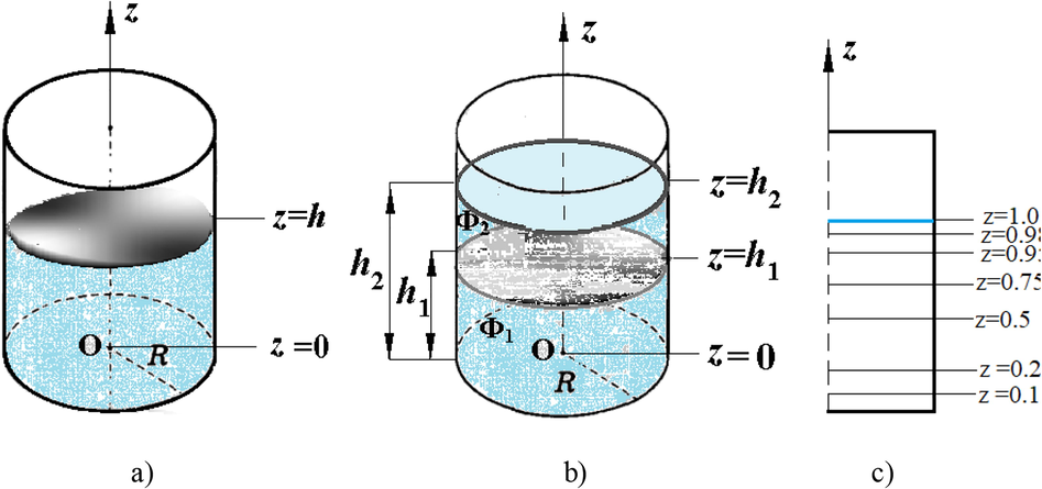
Cylindrical tank with flexible membranes and levels of membrane installation.
In this paper the linear water wave theory is in use. In above formulated suppositions the velocity potential satisfies the Laplace equation
The following boundary value problem (BVP) is formulated for the velocity potential
. In the fluid domain it satisfies the Laplace equation (1). At the wall
and at the bottom
of the cylindrical tank the impermeability conditions are formulated as follows:
To formulate the boundary condition on the free surface, consider at first the following equation of the membrane motion:
where w is a membrane deflection, T is a tension per unit length, μ is mass per unit area of the membrane, p is the liquid pressure on the membrane.
The following boundary conditions are formulated for membrane deflections, at r = R:
On the free liquid surface at
the equality of normal components of liquid and membrane velocities have to be satisfied
as well as the dynamic boundary condition
So, we have coupled boundary value problem (1)-(6) for evaluating the unknown functions Φ and w.
Consider harmonic oscillations and assume that
Using the separation of variables method, we get
where are zeros of the first derivative of Bessel’s function at . From (6) we have the following expression for pressure:
For flexible membrane we suppose that
It would be noted that membrane thickness is negligible. Using above equations for p and w in membrane equation (4), we get
which is a non-homogeneous differential equation. Solution for membrane deflections of Eq. (10) is following:
Condition (5) at
gives
Using condition w = 0 at r = R from (5), we get
So, we have equations (12) and (13) to determine unknown coefficients and unknown frequency .
For a fixed mode m the truncated series are received as
There are constant coefficients before unknowns in equation (14), and variable ones in equation (15), so we have to choose N points including end points in namely,
ri=(Ri)/(N −1), I = 0,1,…N
at the free surface for satisfying equation (15). Then we obtain the following N + 1 homogeneous algebraic equations in the coefficients
:
In (17) we suppose that n1 = 0,1,…N-1.
In matrix form system (16)-(17) can be written as
The condition of a non-trivial solution of system (18) gives the non-linear frequency equation (the equality of the system determinant to zero)
for evaluating the frequencies .
2.2 Liquid vibrations in cylindrical tanks with internal flexible membranes
Free vibrations of the liquid in the cylindrical tank with an internal flexible membrane are considered, Fig. 1b). The incompressible and inviscid liquid is supposed to perform irrotational motion in the fluid domain divided into two sub-domains by internal flexible membrane that is installed at the height h1, Fig. 1c). The first fluid sub-domain is confined by bottom, the lower part of the cylindrical wall, and the flexible membrane. The liquid velocity in this domain is described by potential . The second fluid sub-domain is bounded by the flexible membrane, the upper part of the cylindrical wall, and the free surface. The liquid velocity in this domain is described by potential .
Two BVP are formulated to determine these potentials. So, for potential
we have the Laplace equation
with wall and bottom impermeability conditions as follows:
, r = R, 0 < z < h1, , z = 0. (21)
For potential
we have the analogical BVP with Laplace’s equation
and the next impermeability conditions at the cylindrical wall:
At the free surface
we have
To formulate the boundary conditions on the flexible membrane at
, consider the equation of membrane motion as follows:
The impermeability conditions at
are following:
The additional boundary conditions are formulated for membrane deflections, at r = R
For pressure components at z =
we consider
Assuming that
insert expressions (28) for
into membrane equation (25). Taking into account equations (20), (22), we get at z =
Assuming that
and using the separation of variables method, we get
and considering at z = the following boundary condition
we get truncated series for the fixed mode m
Then we choose N points including end points in at the free surface, namely ri = (Ri)/(N-1), i = 0,1,…N and obtain the following 3 N homogeneous algebraic equations in the coefficients :
for ,
for ,
for .
In matrix form this system can be written as
The condition of a non-trivial solution of system (34) gives the non-linear frequency equation (the equality of the system determinant to zero)
for evaluating the frequencies .
3 Numerical results and discussion
3.1 Validation study
Numerical results are obtained by two methods. First, we obtain frequencies for both considered problems by solving the non-linear equations (19), (35) using combination of Newton and parabolic interpolation methods (Choudhary and Bora, 2017).
To validate our results, the methods based on coupled FEM and BEM methods (Gnitko et al, 2017; 2019; Jamalabadi, 2020), are in use.
Consider the rigid partially filled cylindrical tank with radius R = 0.5 m and filling level h = 1 m. Let the liquid density be ρ = 998 kg/m3.
To testify our numerical results, we compare data for the first non-axisymmetric frequency, obtained by boundary (BEM) and finite (FEM) elements methods with analytical values of Ibrahim (2005), obtained by the following formula where are roots of the equation , J1(x) is the Bessel function of the first kind.
The comparison of numerical results obtained by using coupled BEM and FEM methods with analytical ones is presented in Table 1. The results demonstrate good agreement. In BEM the one-dimensional elements with constant approximation of densities are applied. It would be noted that considered frequency is the lowest one of liquid vibrations in the tank.
Method
Modes of vibrations, n
1
2
3
4
BEM, 40 elements
0.95582
1.62832
2.05986
2.41284
BEM, 400 elements
0.95598
1.62779
2.05979
2.41245
FEM, 12000 elements
0.95576
1.62739
2.05986
2.41223
Analytical solution
0.95597
1.62777
2.05970
2.41198
Fundamental sloshing modes of fluid vibrations are shown in Fig. 2.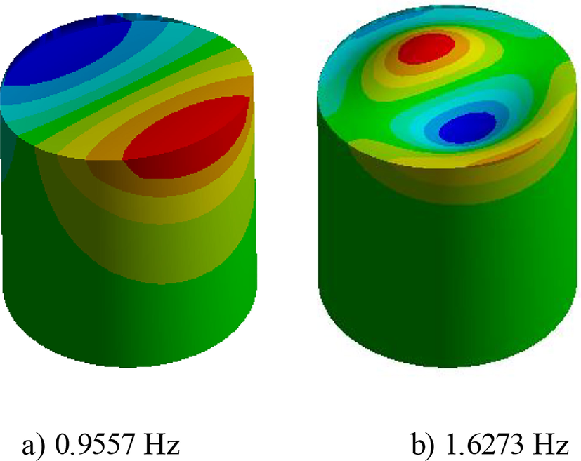
Fundamental sloshing modes and frequencies of liquid in the cylindrical tank,
Next, we consider vibrations of flexible membranes of different materials, without interaction with liquids. Consider the clamped silicon membrane with radius R = 0.5 m, thickness hm = 0.001 m, material density ρm = 2800 kg/m3, Young modulus E = 50Mpa, Poison’s ratio ν = 0.49 and the Eva plastic membrane with radius R = 0.5 m, thickness hm = 0.001 m, material density ρm = 950 kg/m3, Young modulus E = 24.5 MPa, and Poison’s ratio ν = 0.48.
The BVP is solved for the following equation:
with boundary conditions (5). First modes of silicon and Eva plastic membranes that correspond to axisymmetric and non-axisymmetric vibrations are shown in Fig. 3 and Fig. 4, respectively.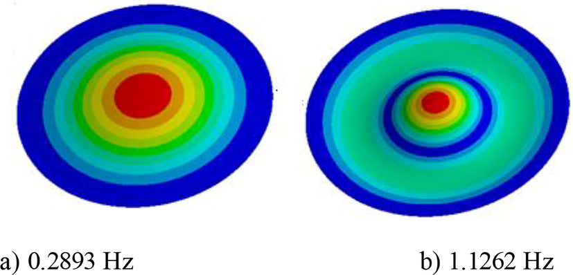
Two first modes and frequencies of plastic membranes axisymmetric vibrations.
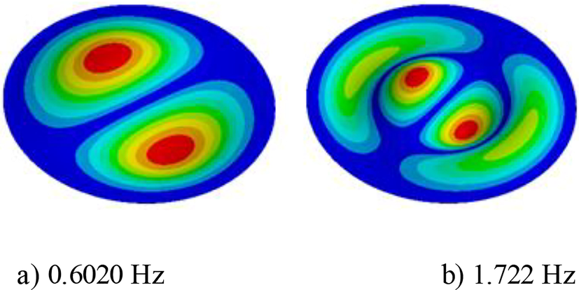
Two first modes and frequencies of plastic membranes vibrations of first harmonic.
For validation study the present BEM-FEM approach is also employed to simulate the hydro-elastic frequencies in an upright cylindrical tank of radius R = 1 m with an elastic free-surface membrane.
Frequencies ω2ijR/g, associated with the first three vibration modes corresponding to the axisymmetric circumferential mode, i = 0;j = 1,2,3, and to non-axisymmetric mode i = 1 and j = 1,2,3 at different filling levels, h/R, ranging from 0.1 to 0.5 for liquid density equal to ρ = 1000 kg/m3 were calculated for comparison with data (Kolaei and Rakhej, 2019). The results were obtained for μ = 1 kg/m2 and T = 10 N/m. Tables 2 shows the first normalized frequencies for different numbers of circumferential mode at different filling levels and relative difference δ between solutions obtained by proposed method and data from (Kolaei and Rakhej, 2019).
i = 0
h/R
ω201R/g
δ
ω202R/g
δ
ω203R/g
δ
0.1
1.412
0.005
4.727
0.006
9.503
0.006
0.2
2.567
0.005
7.310
0.006
11.921
0.006
0.3
3.432
0.005
7.713
0.006
12.012
0.006
0.4
3.994
0.004
8.102
0.005
12.231
0.005
0.5
4.100
0.004
8.106
0.004
12.452
0.004
i = 1
h/R
ω211R/g
δ
ω212R/g
δ
ω213R/g
δ
0.1
1.102
0.006
5.028
0.008
10.209
0.009
0.2
2.516
0.006
6.997
0.008
12.644
0.009
0.3
2.720
0.006
7.510
0.008
12.836
0.009
0.4
2.873
0.005
7.523
0.006
12.837
0.007
0.5
3.015
0.004
7.533
0.004
12.837
0.005
3.2 Coupled membrane and liquid vibrations in cylindrical tanks
Suppose that the flexible membrane is installed into cylindrical tank, or covered the free surface, Fig. 1. Both silicon and Eva plastic membranes are examined. Fig. 5 demonstrates changing in values of frequencies for axisymmetric vibrations of Eva plastic membrane and liquid in dependence of the installation level h1, Fig. 1b) and Fig. 1c). The system “Liquid- Membrane” performs coupled vibrations, and mutual influence of both components is sufficient.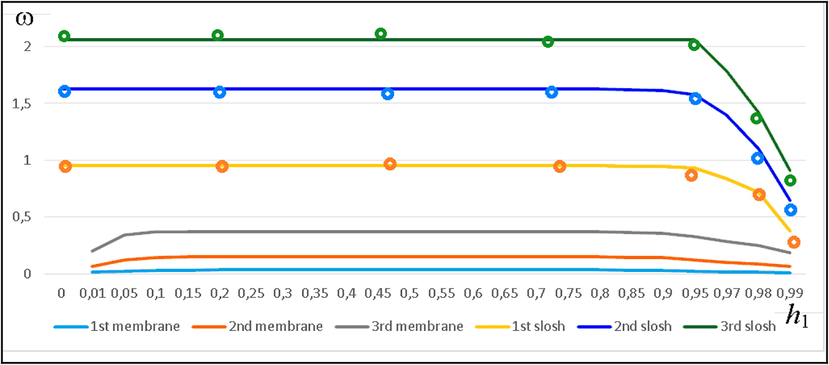
First natural frequencies of the Eva plastic membrane and the liquid free surface (ω) via level (h1).
As follows from numerical simulations, if the membrane is installed inside the cylinder, then the most important parameter affecting the result, is the height h1 of the membrane installation. If the membrane is installed at a considerable distance from the free surface, then the sloshing frequency practically does not change, and more precisely, it slightly increases. This phenomenon is clearly demonstrated in Fig. 5, between 0 and 0.85 value of membrane installation level. Solid lines correspond to calculations made by using BEM-FEM software, points correspond to calculations made by using analytical approach, described above, with N = 40. The results are in good agreement. The difference between analytical and numerical results is near 0.001. When the membrane is near the free surface, the sloshing frequency drops significantly, approaching the membrane frequencies. That is clearly demonstrated in Fig. 5, in the interval from 0.85 to 0.99 values of the membrane installation level.
Also, depending on the vertical arrangement of the membrane, the sloshing modes are also changed.
At low levels of the membrane installation both sloshing modes and frequencies resemble the modes and frequencies of the tank without membranes. When the membrane is close to the free surface, the modes of the latter are exposed to the modes of the membrane, and look different, see Fig. 6a).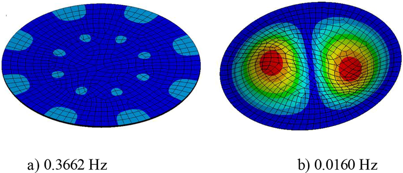
First modes and frequencies: a) first sloshing mode at h1 = 0,99 m, b) first mode and frequency of membrane covered the liquid free surface.
When the membrane is placed on the liquid free surface, the modes and frequencies of the membrane change drastically. Instead of the axisymmetric mode, the mode of first harmonic becomes corresponding to the lowest frequency, Fig. 6b).
The frequencies of the membrane installed in the fluid are significantly reduced due to the added mass of fluid. The lowest frequency of the membrane is obtained when the membrane is near the bottom of the cylinder. With increasing the level of the membrane installation its frequency increases up to the level of installation of 0.5 m. Further, the membrane frequency decreases up to the level of its installation on the free surface of the liquid, where a sharp decrease in the frequency of the membrane occurs. When installing the membrane on the surface of the liquid, the sloshing frequency and the membrane frequency tend to be equal.
The silicon membrane installed in liquid-filled cylindrical tank shows the similar characteristics.
Fig. 7 demonstrates changing values of frequencies of silicon membrane and liquid in dependence of the installation level h1.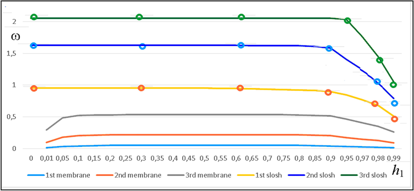
First natural frequencies of the silicon plastic membrane and the liquid free surface (ω) via level (h1).
In case of placing the membrane directly on the free surface, the frequencies and modes of the sloshing practically coincide with ones of the membrane, Fig. 8 and present modes and frequencies of this coupled “Liquid- Membrane” system. As a result, the lowest frequencies of the system with silicon roof on waterline are equal to ω1 = 0.0763 Hz, ω2 = 0.3081 Hz, ω3 = 0.7645 Hz. The lowest frequencies of the system with Eva plastic silicon roof on waterline (without free surface), are equal to ω1 = 0.0527 Hz, ω2 = 0.214 Hz, ω3 = 0.523 Hz.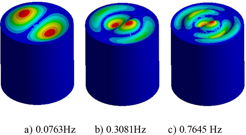
First modes and frequencies of “Liquid-Membrane system”with silicon plastic roof on waterline.
These results show the significant decrease in the frequency of sloshing with membrane on the waterline, compared with installing the membrane at the level of 0.99 m, and the significant increasing in the frequency of the membrane on the waterline compared with internal membrane at the same installation level h1 = 0.99 m.
4 Conclusion
The mathematical model is developed for estimating the influence of baffle elasticity. The flexible membranes are considered as baffles. Two BVP are considered in dependence of the baffle installation level. The internal baffle is installed at different levels. The limit installation level is waterline. In this case membrane can be considered as a covering roof. These two BVP require different approach for their solving. For internal flexible membranes the method of sub-domains is in use both in analytical method and in coupled BEM and FEM methods. Changes in values of frequencies for axisymmetric and first harmonic vibrations of plastic membrane of different materials and liquid in dependence of the installation level are analysed.
If the membrane is installed at a considerable distance from the free surface, then the sloshing frequencies and modes practically do not change, but the membrane frequencies became more smaller Depending on the vertical arrangement of the membrane, the sloshing modes are also changed. At low levels of the membrane installation both sloshing modes and frequencies resemble the modes and frequencies of the cylindrical tank without membranes. When the membrane is close to the free surface, the modes of the latter are exposed to the modes of the membrane and look essentially different. When the membrane is placed on the liquid free surface, the modes and frequencies of the membrane change drastically. Instead of the axisymmetric mode, the mode of first harmonic becomes corresponding to the lowest frequency.
As follows from numerical simulations, if the membrane is installed inside the cylinder, then the most important parameter affecting the result, is the height of the membrane installation. The novelty of proposed approach consists in possibility to study the influence of elastic baffles and roofs in the liquid-filled tanks. The dependencies of frequencies via the filling level are identified.
Acknowledgment
The authors also thankfully acknowledge Professor Alex Cheng, University of Mississippi, USA for his constant support and interest to our research.
Disclosure of Funding
This work was supported by Ministry of Science and Technology, DST, India, and Ministry of Education and Science of Ukraine.
Declaration of Competing Interest
The authors declare that they have no known competing financial interests or personal relationships that could have appeared to influence the work reported in this paper.
References
- The Dynamic Behaviour of Liquids in Moving Containers, NASA SP- 106, Washington, D.C., 1966, updated by Dodge, F.T.. Southwest Research Institute; 2000.
- Sloshing in a three-dimensional rectangular tank: Numerical simulation and experimental validation. Ocean Eng.. 2006;33(16):2135-2149.
- [Google Scholar]
- Vibrations of cicular plates resting on sloshing liquid: solutions of the fully coupled problem. J. Sound Vibr.. 2001;245:261-283.
- [Google Scholar]
- Viscous oscillations in a circular cylindrical tank with elastic surface cover. J. Sound Vib.. 2000;304(1-2):1-17.
- [Google Scholar]
- Finite element computation of sloshing modes in containers with elastic baffles plates. Int. J. Numer. Meth. Eng.. 2003;56(3):447-467.
- [Google Scholar]
- Dynamic response analysis of a liquid filled cylindrical tank with annular baffle. J. Sound Vib.. 2004;274(1-2):13-37.
- [Google Scholar]
- A new approach to the Z-transform through infinite computation. Commun. Nonlinear Sci. Numer. Simul.. 2020;82:105019
- [Google Scholar]
- Finite element analysis of resonant sloshing response in 2-D baffled tank. J. Sound Vib.. 2005;288(4-5):829-845.
- [Google Scholar]
- Free vibration analysis of baffled liquid-storage tanks by the structuralacoustic finite element formulation. J. Sound Vib.. 2002;258(5):847-866.
- [Google Scholar]
- Liquid sloshing in a circular cylindrical container containing a two-layer fluid. International Journal of Advances in Engineering Sciences and Applied Mathematics. 2016;8(4):240-248.
- [Google Scholar]
- Linear sloshing frequencies in the annular region of a circular cylindrical container in presence of a rigid baffle. Sadhana-Acad. Proc. Eng. Sci.. 2017;42(5):805-815.
- [Google Scholar]
- Dodge, F.T., 1971. Study of flexible baffles for slosh suppression, NASA CR-1880.
- Resonant frequencies in a container with vertical baffles. J. Fluid Mech.. 1987;175:295-305.
- [Google Scholar]
- Natural sloshing frequencies and modes in a rectangular tank with a slat-type screen. J. Sound Vib.. 2011;330(7):1490-1503.
- [Google Scholar]
- Gatti, P. L., 2020. Advanced Mechanical Vibrations: Physics, Mathematics and Applications ISBN 9781138542280, 338 p.
- Sloshing in a vertical circular cylindrical tank with an annular baffle. Part 1. Linear fundamental solutions. J. Eng. Math.. 2006;54(1):71-88.
- [Google Scholar]
- Evaluation of sloshing problem by variational boundary element method. Eng. Anal. Boundary Elem.. 2003;27(9):935-943.
- [Google Scholar]
- Gnitko, V., Naumemko, Y., Strelnikova, E., 2017a. Low Frequency Sloshing Analysis of Cylindrical Containers with Flat and Conical Baffles, International Journal of Applied Mechanics and Engineering. 22(4), 867-881. https://doi: 10.1515/ijame-2017-0056.
- Gnitko, V., Degtyariov, K., Naumenko, V., Strelnikova, E., 2018. Coupled BEM and FEM Analysis of fluid-structure interaction in dual compartment tanks, Int. Journal of Computational Methods and Experimental Measurements. 6(6), 976-988. https://doi: 10.2495/CMEM-V6-N6-976-988.
- Gnitko, V. Degtyariov, K. Karaiev, A. Strelnikova E., 2019. Singular boundary method in a free vibration analysis of compound liquid-filled shells, WIT Transactions on Engineering Sciences. 126, WIT Press, 189-200. https://doi: 10.2495/BE420171.
- Liquid Sloshing Dynamics. Theory and Applications. Cambridge University Press; 2005.
- Boundary element analysis of 3-dimensional sloshing problem by using cubic spline element. Naval Architect Japan.. 1989;166:355-362.
- [Google Scholar]
- Frequency analysis and control of sloshing coupled by elastic walls and foundation with smoothed particle. J. Sound Vib.. 2020;476:115310.
- [CrossRef] [Google Scholar]
- Axisymmetric polyharmonic spline approximation in the dual reciprocity method. ZAMM‐J. Appl. Math, Mech./Zeitschrift für Angewandte Mathematik und Mechanik 2021 e201800339
- [CrossRef] [Google Scholar]
- Free vibration analysis of coupled sloshing-flexible membrane system in a liquid container. J. Vib. Control. 2019;25(1):84-97.
- [CrossRef] [Google Scholar]
- Dynamics of rectangular tank with perforated vertical baffle. Ocean Eng.. 2016;126(1):384-401.
- [Google Scholar]
- Sloshing damping in cylindrical liquid storage tanks with baffle. J. Sound Vib.. 2008;311:372-385.
- [Google Scholar]
- Numerical investigation of the behavior of thin flexible membranes in interaction with a fluid domain. Proc. Appl. Math. Mech.. 2016;16:639-640.
- [CrossRef] [Google Scholar]
- Ring damping of free surface oscillations on a circular tank. J. Appl. Mech.. 1958;25(2):274-276.
- [Google Scholar]
- A reduced order model for liquid sloshing in tanks with flexible baffles using boundary element method. Int. J. Numer. Meth. Engng.. 2012;89(13):1652-1664.
- [Google Scholar]
- Free axisymmetric oscillations of a two-layer liquid with an elastic eparator between layers. Russ. Aeronaut. (Iz.VUZ). 2015;58(1):37-41.
- [Google Scholar]
- BEM and FEM analysis of fluid-structure interaction in a double tank. Eng. Anal. Bound. Elements. 2016;67:13-25.
- [CrossRef] [Google Scholar]
- Analysis of flexible baffles for damping tank sloshing. J. Spacecr Rocket.. 1967;4(1):47-53.
- [Google Scholar]
- Liquid vibrations in circular cylindrical tanks with and without baffles under horizontal and vertical excitations. Eng. Anal. Bound. Elements.. 2020;120:13-27.
- [CrossRef] [Google Scholar]
- Boundary element method in nonlinear sloshing analysis for shells of revolution under longitudinal excitations. Eng. Anal. Bound. Elements.. 2020;111:78-87.
- [CrossRef] [Google Scholar]
- Mathematical models for understanding phenomena: Vortex-induced vibrations. Japan Architectural review. 2020;3(4):398-422.
- [Google Scholar]
- Modelling of Liquid Sloshing in Rectangular Tanks with Flow-Damping Devices. Eng. Struct.. 1998;20(7):593-600.
- [Google Scholar]
- Slosh suppression for infinite modes in a moving liquid container. IEEE ASME Trans. Mechatron.. 2015;20(1):217-225.
- [Google Scholar]
- Hydrodynamic study of an anti-sloshing technique using floating foams. Ocean Eng.. 2019;175:62-70.
- [Google Scholar]
- Nonlinear sloshing in rectangular tanks under forced excitation. Int. J Nav. Arch. Ocean Eng.. 2018;10(5):545-565.
- [Google Scholar]


