

Translate this page into:
Gain and bandwidth enhancement of slotted microstrip antenna using metallic nanofilms for WLAN applications
⁎Corresponding author. sunandan.baruah@adtu.in (Sunandan Baruah)
-
Received: ,
Accepted: ,
This article was originally published by Elsevier and was migrated to Scientific Scholar after the change of Publisher.
Peer review under responsibility of King Saud University.
Abstract
Structural modifications on microstrip patch antenna design for performance enhancement offer improvements and advantages only up to a certain limit. However, with the use of novel material in the patch area, the performance of a microstrip patch antenna can further be enhanced in terms of gain and bandwidth. In this paper, a nanomaterial-based slotted rectangular microstrip patch antenna is proposed for gain and bandwidth enhancement in Wireless Local Area Network (WLAN) applications. A conventional copper rectangular microstrip antenna (MSA) with a rectangular slot in the patch area is first fabricated and then nanomaterial is deposited in the slot area. Two types of metallic nanoparticulate thin films are deposited using Gold Nanoparticles (Au NPs) and a combination of alternate Silver-Gold-Silver Nanoparticles (Ag-Au-Ag NPs) in the slot area and the antenna parameters analyzed. A comparison between the conventional slotted MSA, and the fabricated antenna with the two different nanoparticulate thin films is presented. It is found that the Au NPs based antenna shows a 12.5 % improvement in bandwidth for a return loss of −31 dB and a 0.5 dB enhancement in gain with a nanomaterial film thickness of 264 nm. The composite Ag-Au-Ag NPs based antenna shows even better performance than the former one with an 18.75 % improvement in bandwidth for a return loss of −30 dB along with gain enhancement of 2 dB with a nanomaterial film thickness of 330 nm. Both the Au NPs and Ag-Au-Ag NPs based antennas are found to resonate at 5.89 GHz and 5.81 GHz showing an electrical size reduction of 32.09 % and 31.15 %, respectively compared to the conventional rectangular MSA.
Keywords
Gold nanoparticles
Silver nanoparticles
Slotted microstrip antenna
Return loss
Bandwidth
Gain

- WLAN
-
Wireless Local Area Network
- MSA
-
Microstrip Antenna
- Au NPs
-
Gold Nanoparticles
- Ag-Au-Ag NPs
-
Silver-Gold-Silver Nanoparticles
- ANN
-
Artificial Neural Networks
- DGS
-
Defected Ground Structures
- Ag NPs
-
Silver Nanoparticles
- HAuCl4
-
Chloroauric Acid
- DI
-
Deionized Water
- Na3C6H5O7
-
Trisodium Citrate Dehydrate
- AgNO3
-
Silver Nitrate
Abbreviations
1 Introduction
With the rapid advancements in communication technology, design of new and efficient antennas has received attention of researchers around the globe. With the rapid evolution of WLAN, antenna engineers are working more into finding new solutions and improving antenna performances to be suitable for WLAN applications. For such applications, antennas are required to be simple and compact and have a wide bandwidth along with improved radiation properties (Liu et al., 2012). Recently, slotted microstrip antennas are gaining popularity in today’s communication industry owing to their numerous advantages. A variety of structural modifications on the patch to achieve good impedance matching and bandwidth have been reported in the open literature (Shivnarayan et al., 2005; Misran et al., 2009; Chang and Weng, 2015; Lozada et al., 2017; Sarma et al., 2015a; Das et al., 2019), including L-shaped slot (Nirmen and Hamad, 2016), S-shaped slot (Ennasar et al., 2015), F-shaped slot (Gautam et al., 2016), U-shaped slot (Zimu et al., 2016; Bhan et al., 2015; Wu et al., 2013) etc. U-shaped open slots are cut in (Liu et al., 2011) to improve the bandwidth. However, U-slot configuration increases the cross-polarization (Costanzo and Costanzo, 2013). A novel compact tri-band printed antenna with multiple shaped slots having a wide impedance bandwidth is presented in Li et al. (2013). Demircioglu et al. (2015) proposed a multiband microstrip patch antennas for bandwidth enhancement using symmetrical rectangular/square slots etched. The parameters of the slot were modeled using Artificial Neural Networks (ANN) which ultimately consumes more power and time thereby making the design complex. In most of these works, the focus is on analyzing different slot size and shape and enhancing the bandwidth. However, one major drawback in slot antennas is that they result in reduced gain. Wong et al. (2020) and Sarmah et al. (2015b) have used slotted antenna to obtain dual-band antenna characteristics with improved return loss. However, the obtained gain in both the works is less and not much discussion on its improvement is provided. Commonly available literature for gain enhancement include Defected Ground Structures (DGS). Khandelwal et al. (2013), Samsuzzaman et al. (2014) and Ghosh and Basu, 2019 discussed about antennas with DGS for gain enhancement. Again, incorporating DGS increases the side lobes of the antenna which further leads to loss of useful power. Thus, methods for gain improvement needs to be addressed in slotted MSA.
The potential of nanotechnology to realize designs at a very small scale can offer a very promising alternative to the existing antenna technologies. Nanotechnology based antenna designs with the inclusion of magnetic nanomaterials, semiconducting nanoparticles, nanofilms, carbon nanotubes, graphene, etc. can be used to improve various properties of an antenna like size reduction, gain, bandwidth, and impedance matching, few of which are reported in (Patil, et al., 2013; Lukacs, et al., 2015; Khan, et al., 2016; Guo, et al., 2017; Matyas, et al., 2017). Most of these works are either based on simulation or focusses more on the printing technology rather than on antenna performance improvement. In Ambalgi and Kamalapurkar (2021), an 8.71 GHz operated Au NPs based MSA is analyzed. The entire patch area along with the slots over the patch are coated with Au NPs deposited through a sputtering technique. However, the bandwidth and gain enhancement was attributed to the presence of multiple wide slots over the patch. A similar work was reported in (Ambalgi et al., 2021), where the entire copper layer from the FR4 epoxy substrate was etched out and a slotted titanium oxide thin film was sputtered and used as the patch. Moreover, literature review confirms that structural modifications on the patch can enhance the antenna performance only upto a certain limit. By using novel materials along with the microstrip structure, there is a possibility in further enhancement in the radiation property such as gain and bandwidth of a conventional MSA. So, in this paper a nanomaterial based slotted rectangular microstrip antenna is proposed for further enhancement of the gain and bandwidth of a conventional slotted MSA for WLAN applications. Firstly, a conventional copper based rectangular slotted MSA is designed and fabricated over an FR4 epoxy substrate. Rectangular slot size of 20 mm × 8 mm was adopted for optimum results. The same antenna is then fabricated by depositing thin films of metallic nanoparticles over the slot using drop and dry method. Two different antennas are fabricated by depositing two different nanoparticulate thin films; Au NPs and alternate layers of Ag-Au-Ag NPs over the slot. Firstly, for the Au NPs based antenna a thin film of approximate thickness 88 nm was used followed by another with thickness of 264 nm. Secondly, for the Ag-Au-Ag based antenna, a thin film of approximate thickness 110 nm was used followed by another with thickness of 330 nm. The antenna parameters are analyzed and a comparison of all the fabricated antennas with different thin films is made.
2 Antenna structure
The geometry of the proposed antenna with inset feed is shown in Fig. 1.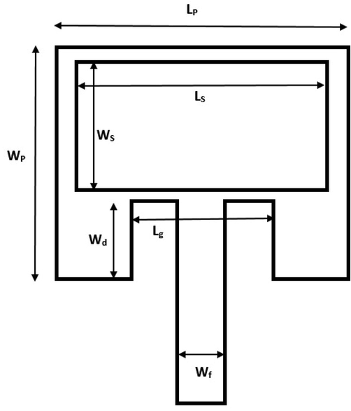
Geometry of the proposed C band antenna.
As mentioned, the antenna is designed over an FR4 epoxy substrate having a relative permitivity εr = 4.4. Initially, a rectangular patch antenna was designed to operate at 4 GHz. The signal feeding to the antenna was done with a rectangular microstrip line of 50 Ω impedance. To achieve better impedance matching between microstrip antenna and feed line, a rectangular slot along with inset cut was introduced in the microstrip patch antenna. The size of the patch is related to the operating frequency and hence for a definite frequency and substrate thickness, the proper size of the ground plane, radiating patch, and inset depth can be determined from a set of well-defined relationships (Balanis, 2016). In order to have efficient radiation in the rectangular patch antenna, the practical width of the antenna can be calculated using the following equation:
The length of the antenna can be calculated using (2).
The inset depth effects the resonant frequency and is given by
The inset gap is arbitrarily chosen.
Using the above equations, the dimensions of the patch are calculated and are provided in Table 1.
Parameters
Dimensions
Length of the patch,
17.45 mm
Width of the patch,
22.82 mm
Length of the ground plane,
26.45 mm
Width of the ground pane,
31.82 mm
Height of the substrate,
1.5 mm
Inset gap,
6 mm
Inset depth,
5.36 mm
Width of the microstrip feed line,
3 mm
Length of the slot,
20 mm
Width of the slot,
8 mm
3 Fabrication of the nanomaterial based antenna
As mentioned in Section 1, two types of metallic NPs were deposited over the slot area. The materials that were synthesized include Au NPs and Silver Nanoparticles (Ag NPs) both having spherical geometry. The synthesis procedures of these nanoparticles are discussed in the subsections below:
3.1 Synthesis of Au NPs
Au NPs were synthesized following a method proposed by Turkevich et al. (1951). Chloroauric acid (HAuCl4) of 5 mM is prepared in deionized (DI) water and used as stock solution. 2 mL of this solution is added to 50 mL of DI water and then heated under stirring until it reaches its boiling point. 2.8 mL of 25 mM Trisodium Citrate Dehydrate (Na3C6H5O7) in DI water is then added into the above mixture and boiled further. When the color of the solution gradually changes from yellowish to reddish, it is kept in an ice bath and allowed to stabilize to get Au NPs.
Au ions through the dissociation of HAuCl4 are reduced using trisodium citrate as the reducing agent. The thermal agitation through heating results in the nucleation of Au NPs which increase in size through Oswald ripening. When the desired size is reached the reaction is quenched using an ice bath.
3.2 Synthesis of Ag NPs
For synthesis of Ag nanospheres, a similar method as described in subsection 3.1 for synthesis of Au NPs is adopted where the salt is Silver Nitrate (AgNO3) and the reducing agent is Na3C6H5O7. After the synthesis of both the nanomaterials, the particles are deposited over the slot using drop and dry or drop casting method (Kaliyaraj et al., 2020). For the fabrication of the Au NPs based antenna firstly, 200 µL of the synthesized material is dropped over the slot area and dried at 100 °C in a hot plate. The parameters of the designed antenna are then measured and analyzed. The same procedure is repeated again by applying three droppings of the same material. For the fabrication of the Ag-Au-Ag NPs based antenna, alternate droppings of Ag NPs, AuNPs and then again Ag NPs of 200 µL each is first dropped over the slot and dried. After analysis of the antenna performance parameters, the process is repeated with three droppings of alternate Ag-Au-Ag NPs. The structure of the fabricated antennas with Au NPs and Ag-Au-Ag NPs are shown in Fig. 2(a) and (b), respectively.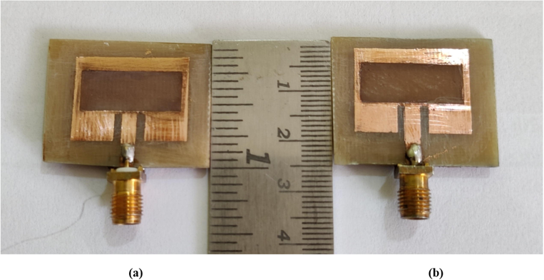
Structure of fabricated (a) Au NPs deposited antenna and (b) Ag-Au-Ag NPs deposited antenna.
4 Theoretical analysis of the proposed antenna
The High Resolution Transmission Electron Microscopy (HR TEM) micrograph of the synthesized Au NPs and Ag NPs are shown in Fig. 3(a) and (b), respectively. From the images, the average size (diameter) of the particles have been measured using ImageJ software.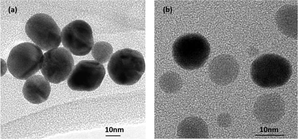
(a) HR TEM micrograph of Au NPs and (b) HR TEM micrograph TEM of Ag NPs.
The 3D structure of the conventional slotted MSA is shown in Fig. 4(a). The height of the FR4 substrate is 1.5 mm, the thickness of the patch, the microstrip inset feedline and the ground plane is 0.05 mm. Fig. 4(b) and 4(c) shows the 3D structure of the MSA when a single and three droppings of NPs is deposited respectively, in the slot area. The thickness of the film formed over the slot region for both the cases of Au NPs based MSA and Ag-Au-Ag NPs based MSA is calculated. Table 2 shows all the estimated values for both the Au NPs based MSA and the Ag-Au-Ag based MSA.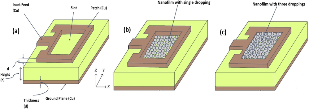
3D structure of (a) Conventional slotted antenna (b) Proposed nanomaterial based antenna for one dropping and (c) Proposed nanomaterial based antenna for three droppings of NPs.
Type
No. of layers
Approximate thickness of the nanoparticulate thin film (nm)
Au NPs based MSA
4
88
12
264
Ag-Au-Ag NPs based MSA
Ag – Au – Ag
1 4 1110
Ag – Au – Ag | Ag – Au – Ag | Ag – Au – Ag
1 4 1 | 1 4 1 | 1 4 1330
5 Results & discussions
5.1 Return loss & bandwidth analysis
Fig. 5(a) shows S11 parameters of the fabricated conventional slotted MSA and Au NPs deposited antenna for nanofilm thickness of 88 nm and 264 nm. The S11 measurements are done using using ZNB20 Vector Network Analyzer.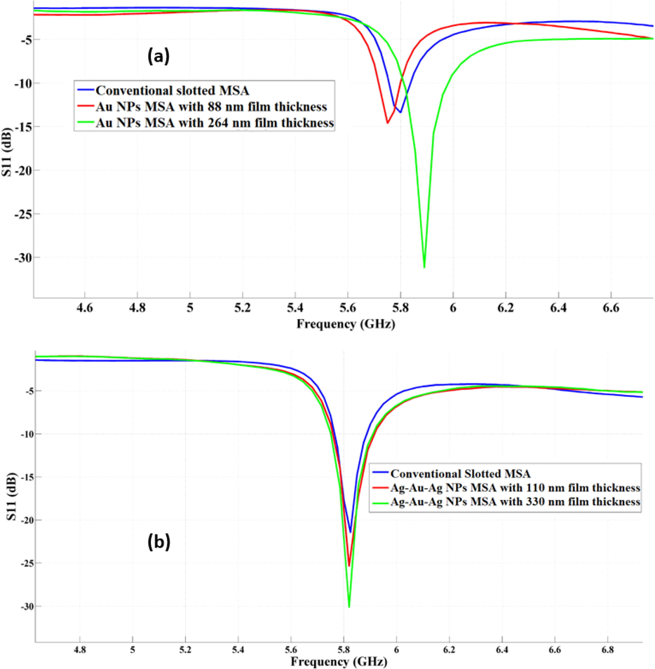
(a) Comparison of S11 parameters of conventional MSA & Au NPs based MSA for nanofilm thickness of 88 nm & 264 nm (b) Comparison of S11 parameters of conventional MSA & Ag-Au-Ag NPs based MSA for nanofilm thickness of 110 nm & 330 nm.
From the figure it can be seen that the conventional slotted MSA resonates at 5.8 GHz and so does the nanomaterial deposited antenna for both 88 nm and 264 nm film thickness. During the theoretical analysis the antenna was designed to operate at a frequency of 4 GHz. The observed shift in operating frequency in the fabricated antenna is due to the introduction of the slot in the original rectangular patch antenna which actually decreases the electrical length of all the three antennas. The return loss and the bandwidth for the Au NPs deposited antenna with 88 nm film thickness is found to be −15 dB and 0.10 GHz respectively. However, with a film thickness of 264 nm the same antenna shows a return loss of −31 dB which is quite low compared to the conventional slotted MSA which shows a return loss of only −20.5 dB. Minimized return loss signifies improvement in impedance matching in the antenna design. This antenna also shows a bandwidth improvement of 12.5 %. The bandwidth is found to be 0.18 GHz which is better than 0.16 GHz as achieved by the conventional slotted MSA. Fig. 5(b) shows S11 parameters of the fabricated conventional slotted MSA and alternately layered Ag-Au-Ag NPs antenna with the two different nanofilm thickness. It can be seen from the figure that both the antennas with 110 nm film thickness and 330 nm film thickness resonates at 5.81 GHz and shows a return loss of −25.5 dB and −30 dB, respectively. Further, both antennas show an improvement of 18.75 % in the bandwidth compared to the conventional slotted MSA. It can be found in all the cases that compared to the conventional slotted MSA the nanomaterial-based antennas show a considerable improvement in return loss and bandwidth specifically with three droppings of deposition (∼264 nm for Au NPs and ∼330 nm for Ag-Au-Ag NPs). Also, all the antennas provide a decrease in the electrical length thereby contributing towards physical size reduction of 32.09 % (Au NPs based MSA) and 31.15 % (Ag-Au-Ag based MSA). Since all the fabricated antennas resonates at the 5.8 GHz to 5.9 GHz range they are well suited for WLAN applications. Table 3 highlights the measurement parameters of this section.
Patch with different materials
Approximate film thickness (nm)
Operating frequency(GHz)
Return Loss (dB)
Bandwidth (GHz)
Conventional slotted MSA
__
5.8
−20.5
0.16
Au NPs deposited MSA
88
5.89
−15
0.10
264
5.89
−31
0.18
Alternate droppings of Ag-Au-Ag NPs deposited MSA
110
5.81
−25.5
0.17
330
5.81
−30
0.19
5.2 Radiation pattern & gain analysis
As discussed in subsection 5.1, the return loss for both the NPs deposited antennas show better results for three droppings (∼264 nm for Au NPs and ∼330 nm for Ag-Au-Ag NPs) compared to single dropping of material, and hence in this section the radiation pattern and gain is analyzed only for antennas having thicker nanofilms. The radiation pattern plots for the proposed antennas are illustrated in Fig. 6. These measurements are done using Antenna Radiation Measurement System from Diamond Engineer, US. Fig. 6 (a) and 6 (b) shows the comparison of 2D radiation pattern in the elevation plane and azimuth plane for the conventional slotted MSA and the Au NPs deposited antenna for nanofilm thickness of 264 nm, respectively.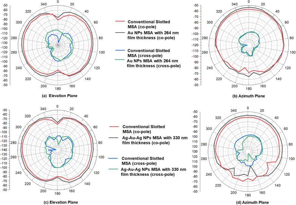
(a) Comparison of 2D radiation pattern of conventional slotted MSA & Au NPs in both elevation and azimuth planes for 264 nm film thickness (b) Comparison of 2D radiation pattern of conventional slotted MSA & Ag-Au-Ag NPs in both elevation and azimuth planes for 330 nm film thickness.
It can be seen from the pattern that a slight improvement in gain (about 0.5 dB) is observed in both elevation and azimuth plane for the Au NPs deposited antenna. Fig. 6(c) and (d) shows the comparison of 2D radiation pattern in the elevation plane and azimuth plane respectively, for the conventional slotted MSA and the alternate Ag-Au-Ag NPs deposited antenna. From both the figures, the nanomaterial-based antenna is found to have a considerable improvement in the pattern with a 2 dB improvement in gain for both elevation and azimuth planes. The cross-polarized components for both the nanomaterial-based antennas is also found to be less compared to the co-polarized components which signifies improvement in the pattern. The radiation pattern exhibits a wide beam in the azimuth plane with minimized back lobe.
The current distribution in the MSA with a rectangular slot is along the edges of the antenna boundary and the slot area. This introduces an inductive effect in the copper patch area and a capacitive effect in the slot region. This capacitance in the slot region shifts the resonating frequency of the original MSA without slot from 4 GHz to 5.8 GHz in the slotted MSA. Thus, it can be said that the shift in frequency decreases the electrical length thereby causing size reduction of the original patch. Now, when Au NPs are dropped into the slot, it forms thin layers of NPs over the slot. These NPs have extremely huge relative surface area which provides high contact area for reactivity with surrounding materials. As such, the presence of the conductive Au NPs layer provided the necessary contact between the slot and the copper patch with increased surface area for better impedance matching and reduced S11 value compared to the conventional slotted MSA. However, the gain in this antenna is almost similar to the conventional slotted MSA with only 0.5 dB enhancement. In case of the Ag-Au-Ag NPs based MSA, considerable gain enhancement can be seen along with return loss and bandwidth enhancement. This is because of the introduction of two different types of nanomaterials in the slot area. The particle size of Au NPs is 22 nm which is larger compared to Ag NPs whose particle size is only 11 nm. Smaller nanoparticles tend to have higher reactivity due to a high surface area to volume ratio, whereas larger particles may act more as reinforcement. Surface contact between neighboring Au NPs will create pathways through which thermal radiation and electrical current gets enhanced causing increased radiation. From circuits point of view also, the presence of alternate layers of Ag and Au in the later antenna introduces a capacitance in between the two different materials at high frequency which also had a positive effect on the performance of the antenna. However, for both the proposed antennas, an interesting observation has been made that the performance saturates at three droppings of nanomaterial (∼264 nm for Au NPs and ∼330 nm for Ag-Au-Ag NPs) and no further improvement was observed in the impedance matching beyond those thicknesses. This is because the thin film achieves a level of smoothness and beyond that the surface morphology simply repeats. The performance with nanofilm thickness of ∼88 nm for Au NPs based MSA and a ∼110 nm for Ag-Au-Ag based antenna is satisfactory without much improvement because of the fact that necessary electrical contact between the copper patch and the nanofilm is not obtained in the slot depth of 0.05 mm with those thicknesses. Thus, it can therefore be concluded that return loss, bandwidth and gain of a slotted MSA can be enhanced through deposition of metallic nanoparticulate films of significant size and thickness to create necessary electrical conductivity in the antenna. Moreover, the proposed designs are also cost effective in the sense that the nanoparticles synthesized were of very low concentration of reactants, and hence, the expenditure involved for the nano-coating is very nominal.
6 Conclusion
Gain and bandwidth enhancement of a slotted microstrip patch antenna using nanomaterial is proposed for WLAN applications. Two nanomaterial-based slot antennas are fabricated and tested where two different types of metallic nanoparticulate using Au NPs and Ag-Au-Ag NPs is deposited over the slot area. The experimental results show improvement in return loss, bandwidth and gain. The Au NPs based antenna shows a return loss of −31 dB, a bandwidth of 0.18 GHz and a 0.5 dB improvement in gain with nanomaterial film thickness of 264 nm compared to the conventional slotted MSA. The Ag-Au-Ag NPs based antenna shows a return loss of −30 dB, a bandwidth of 0.19 GHz and a 2 dB improvement in gain with nanomaterial film thickness of 330 nm as compared to its conventional counterpart. The performance improvement in the later antenna is due to the introduction of a capacitance in between the two different nanomaterials. Both the antennas are found to resonate in the 5.8 GHz to 5.9 GHz band which shows that the proposed antennas are well suited for WLAN applications.
Acknowledgement
The authors acknowledge the Center of Excellence in Nanotechnology (CoEN), Assam Don Bosco University, Center of Excellence in Nanotechnology (CoEN), Assam down town University and Antenna Measurement Laboratory, Dept. of ECT, Gauhati University for allowing access to their facilities.
Disclosure of funding
This research did not receive any specific grant from funding agencies in the public, commercial, or not for-profit sectors.
Declaration of Competing Interest
The authors declare that they have no known competing financial interests or personal relationships that could have appeared to influence the work reported in this paper.
References
- Analysis of 8.71 GHz operated gold nanoparticles based multi-slotted patch antenna etched on epoxy dielectric material having broadsided radiation characteristics. Mater. Today:. Proc.. 2021;43:3810-3814.
- [Google Scholar]
- Design, modeling and experimental study of GHz patch antenna coated with conductive layer of nanomaterial for enhanced characteristics with defected ground structure in communication network applications. SN Computer Sci.. 2021;2:152.
- [CrossRef] [Google Scholar]
- Antenna Theory: Analysis and Design (fourth ed.). Wiley; 2016.
- Quad bands U-shaped slot loaded probe fed microstrip patch antenna. 2nd Int Conf. Adv. Comput. Commun. Eng. 2015:409-412.
- [CrossRef] [Google Scholar]
- Chang, M., Weng, W., 2015. A printed multi-band slot antenna for LTE / WLAN applications. International Symposium on Antennas and Propagation & USNC/URSI National Radio Science Meeting. 1144–1145. http://dx.doi.org/ 10.1109/APS.2015.7304960.
- Compact U-slotted antenna for broadband radar applications. J. Electr. Comput. Eng.. 2013;910146
- [Google Scholar]
- Das, S. R., Kashyap, P. A., Sarma, K. K., Baruah, S., 2019. Nano-sized slotted microstrip patch antenna for X band operation. 2nd International Conference on Innovations in Electronics, Signal Processing and Communication. http://dx.doi.org/ 10.1109/IESPC.2019.8902438.
- Slot parameter optimization for multiband antenna performance improvement using intelligent systems. Int. J. Antennas Propagation. 2015;2015:1-11.
- [Google Scholar]
- Ennsar, M. A., Aznabet, I., Essaaidi, M., Group, M., 2015. A compact modified S-shaped RFID tag antenna for metallic applications. IEEE 15th Mediterranean Microwave Symposium. 8–10. http://dx.doi.org/ 10.1109/MMS.2015.7375407.
- Design of compact F-shaped slot triple-band antenna for WLAN / WiMAX applications. IEEE Trans. Antennas Propag.. 2016;64(3):1101-1105.
- [Google Scholar]
- Triangular slotted ground plane: a key to realizing high-gain, cross-polarization-free microstrip antenna with improved bandwidth. Turk. J. Electr. Eng. Comput. Sci.. 2019;27:559-1570.
- [CrossRef] [Google Scholar]
- Flexible and wearbable 2.45GHz CPW-FED antenna using inkjet printing of silver nanoparticles on PET substrate. Microwave Opt. Technol. Lett.. 2017;59:204-208.
- [CrossRef] [Google Scholar]
- A mini-review: How reliable is the drop casting technique? Electrochem. Commun.. 2020;121:106867.
- [Google Scholar]
- Inkjet printed transparent and bendable patch antenna based on polydimethylsiloxane and indium tin oxide nanoparticles. Microwave Opt. Technol. Lett.. 2016;58:2884-2887.
- [CrossRef] [Google Scholar]
- Design and analysis of microstrip DGS patch antenna with enhanced bandwidth for Ku band applications. International Conference on Microwave and Photonics 2013
- [CrossRef] [Google Scholar]
- CPW-fed S-shaped slot antenna for broadband circular polarization. IEEE Antennas Wirel. Propag. Lett.. 2013;12:619-622.
- [CrossRef] [Google Scholar]
- Compact open-slot antenna with bandwidth enhancement. IEEE Antennas Wirel. Propag. Lett.. 2011;10:850-853.
- [CrossRef] [Google Scholar]
- Compact CPW-fed tri-band printed antenna with meandering split-ring slot for WLAN/WiMAX applications. IEEE Antennas Wirel. Propag. Lett.. 2012;11:1242-1244.
- [CrossRef] [Google Scholar]
- Design and study of a microstrip slot antenna operating at 2.8/3.1/3.6/4.7/5.4 GHz. MATEC Web of Conferences. 2017;125:03003.
- [Google Scholar]
- UWB antenna based on nanoparticles of silver on polyimide substrate. 38th Int. Spring Seminar on Electronics Technology; 2015. p. :408-413.
- Microstrip antenna from silver nanoparticles printed on a flexible polymer substrate. Mater. Today:. Proc.. 2017;4(4):5030-5038.
- [Google Scholar]
- Design analysis of a slotted microstrip antenna for wireless communication. International Journal of Electronics and Communication Engineering. 2009;3(1):34-36.
- [CrossRef] [Google Scholar]
- Tri-band microstrip antenna with L-shaped slots for bluetooth /WLAN / WiMAX applications. 33rd Natl. Radio Sci. 2016 Conf. 73–80
- [CrossRef] [Google Scholar]
- Design and simulation of nanotechnology based proximity coupled patch antenna at X-band. Int. J. Adv. Res. Comput. Commun. Eng.. 2013;2:3344-3348.
- [Google Scholar]
- Printed wide-slot antenna design with bandwidth and gain enhancement on low-cost substrate. Sci. World J.. 2014;2014:1-10.
- [Google Scholar]
- Sarma, A., Sarmah, K., Sarma, K.K., 2015a. Low return loss slotted rectangular microstrip patch antenna at 2.4GHz. 2nd International Conference on Signal Processing & Integrated Networks. 631-635. http://dx.doi.org/ 10.1109/SPIN.2015.7095333.
- Dual-band microstrip patch antenna loaded with complementary split ring resonator for WLAN applications. Information Systems Design and Intelligent Applications. Adv. Intell. Syst. Comput.. 2015;339:573-580.
- [CrossRef] [Google Scholar]
- Analysis of slot loaded rectangular microstrip patch antenna. Indian J. Radio Space Phys.. 2005;4:424-430.
- [Google Scholar]
- A study of the nucleation and growth processes in the synthesis of colloidal gold. Discuss. Faraday Soc.. 1951;11:55-75.
- [CrossRef] [Google Scholar]
- Very-low-profile grounded coplanar waveguide-fed dual-band WLAN slot antenna for on-body antenna application. IEEE Antennas Wirel. Propag. Lett.. 2020;19. 1:213-217.
- [CrossRef] [Google Scholar]
- Wu, Q., Shi, L., Zhao, G., (2013). Design of a Ku-band broadband U-slot microstrip antenna. IEEE International Conference on Microwave Technology and Computational Electromagnetics. 212–215. http://dx.doi.org/ 10.1109/ICMTCE.2013.6812463.
- Zimu, Y., Hou, Z., Leiming, Z., An, W., (2016). A U shaped slot antenna for WLAN and WiMAX applications. 7th Asia Pacific International Symposium on Electromagnetic Compatibility. 152–154. http://dx.doi.org/ 10.1109/APEMC.2016.7522993.
Appendix A
Supplementary data
Supplementary data to this article can be found online at https://doi.org/10.1016/j.jksus.2022.102374.
Appendix A
Supplementary data
The following are the Supplementary data to this article:


