Translate this page into:
Experimental and computational studies on honeycomb sandwich structures under static and fatigue bending load
⁎Corresponding author. naseem@cau.ac.kr (Naseem Abbas)
-
Received: ,
Accepted: ,
This article was originally published by Elsevier and was migrated to Scientific Scholar after the change of Publisher.
Peer review under responsibility of King Saud University.
Abstract
Sandwich structures with glass fiber face sheets and aluminum honeycomb core are investigated computationally and experimentally. A three point bending load arrangement is conducted to examine the static and fatigue performance of honeycomb sandwich panel. Under static loading, the load and displacement response is indicated in five phases. The decrease in fatigue life with load level was observed in approximately linear manner. The visual and Scanning Electron Microscopic (SEM) analysis were carried out to analyze the failure modes. For static and high amplitude fatigue load, the failure initiates due to face yielding, while for low fatigue load failure initiates as a result of delamination at core and skin interface. However, in all cases principle failure mode is indentation. The honeycomb sandwich structure was also modeled with commercially available finite element packages ANSYS and the fatigue analyses were carried out to determine the life of specimens under load-displacement response. The experimental results were in good agreement with the Finite Element Analysis (FEA) results in both static and fatigue loads, and fracture modes prediction.
Keywords
Sandwich structures
Bending load
Finite element
Fatigue life
Failure modes
Face yielding
1 Introduction
The use of honeycomb sandwich structures is increasing in many areas such as aerospace, aeronautics, railway, marine, civil infrastructures, automobiles and packaging because of the higher shear/bending stiffness per unit weight and higher thermal/corrosion resistance (Gholami et al., 2016; He et al., 2016; Krzyżak et al., 2016; Loja et al., 2015). The behavior of sandwich panels mainly depends upon the geometric configuration and materials of core and facing (Manshadi et al., 2016). Nowadays several types of cores are available for making the whole structure suitable for light weight applications (Daniel and Abot, 2000). But corrugated truss and honeycomb cores are preferable and increases the stiffness and rigidity of panels (Xu et al., 2016). Similarly the failure behavior of sandwich structures also depends upon the geometric configurations, materials types and loading arrangement (Banghai et al., 2015; Daniel et al., 2002; Sakly et al., 2016). Therefore, it is necessary to investigate the failure mechanism of each type of sandwich structure individually. In any industrial area it is preferred to use the honeycomb sandwich structure of high stiffness and strength. Hence the selection of optimal honeycomb sandwich panel is challenge from long time. A number of experimental studies have been done to determine the mechanical properties as well as the flexural strength and fatigue life of honeycomb sandwich panels. It is not easy to investigate the fatigue performance of all types of honeycomb sandwich structures using the experimental techniques because of the large number of available materials. Therefore it is important to use the computational tools after the experimentation for the selection of required honeycomb panel within short time.
A lot of researchers have developed the mathematical models for the investigation of static and fatigue response of honeycomb sandwich panels that are difficult to use because of the presence of large number of coefficients and parameters based on experimentations. Instead of this few researchers have used the different commercially available tools such as ABAQUS and ANSYS for the investigation of the particular behavior of sandwich structures. Abbadi et al. (2015) performed fatigue testing to investigate the behavior of honeycomb with and without the artificial defect. It is concluded that there is no effect of defects on static response. The fatigue life is more influenced by drilling type defect as compared to brinell. At higher loading levels, the failure is observed due to compression of facing but at lower loading levels the failure is found due to the crack of face sheet. Strength of GFRP sandwich panels with several core materials was investigated by experimentation as well as the simulation using the ANSYS APDL software by Herranen et al. (2012). It was found that the total variation in thickness of core and facing remains same and use of core of polymethacrylimide doesn’t causes the any improvement in strength. Vyacheslav et al. (Burlayenko and Sadowski, 2009) used the ABAQUS for the investigation of the performance of sandwich panels with foam filled honeycomb and hollow cores. The deformation-based homogenous technique using FEM was used to determine the elastic properties of core, load carrying abilities and the natural frequencies. It was concluded that in case of foam filled honeycomb the stiffness of buckling load increases.
Mota et al. (Moita et al., 2016) extended the FEM for the determination of non-linear static behavior of sandwich plate/curved shell structures. On the basis of comparison with alternative models it is concluded that the ESL HSDT8 model is not suitable when there is more difference in properties of core and face sheets of sandwich plate-curved shell structures and an alternative model on the basis of simple flat triangular finite element may reduce the computation time when it is compared with 3D FEM. The 3D FEM was implemented by Sakly et al. (2016) to investigate the low velocity impact response of sandwich structures used for railways. The results were confirmed with the experimentation. Debonding of skin core interface, compression and core shear failure were observed under impact load. The failure mechanism of corrugated core sandwich structures under low velocity impact loading is also investigated by Wentao, H. et al. (He et al., 2016) using the ABAQUS.
An analytical and experimental model was developed by Boukharouba et al. (2014) to predict and examine the fatigue life and failure mode of honeycomb sandwich structures under three point bending load. The analytical approach was based on coefficients and empirical functions depends upon the experimental data as well as the properties of materials. The stiffness degradation with the increase of number of cycles is observed. Numerical methods play a significant role in solving today engineering problems Silori et al. (2015). The use of fatigue analysis method based on the finite element method is gradually increasing after the development of finite element numerical method using computer technology (Zhang et al., 2016). ANSYS is most common software used for finite element analysis (Liu et al., 2016). Silori et al. (2015), Zhang et al. (2016), and (Liu et al. (2016) used the ANSYS workbench for the prediction of strength and fatigue life of gear, front axle beam and impeller respectively. In all these three studies fatigue life of panel is investigated in static structural analysis by selecting load- displacement or stress-strain relationship. The same method is adopted in this research work.
The strength and stiffness of sandwich structures mainly determined from the static and fatigue loading conditions. As discussed above, many analytical and experimental methods have been developed to predict the static and fatigue performance of honeycomb sandwich structures. The use of computational methods based on FEM is increasing rapidly to solve the real problems in few years (White, 1988). The commercially available packages ANSYS is user friendly and most easy to analyze the required designed model (White, 1988). Several responses of honeycomb sandwich structures have been investigated using the ANSYS. However, to the authors’ knowledge, no study has been performed on the fatigue behavior of honeycomb sandwich structures using ANSYS. So the purpose of this study is to develop the computational method based on actual experimental conditions for the prediction of static and fatigue performance of honeycomb sandwich structures. Material Testing System (MTS-810) and commercially available software ANSYS are used for the determination of flexural strength and fatigue life of aluminum honeycomb sandwich structures under three point bending conditions. The failure modes were predicted on the basis of visual and Scanning Electron Microscopic (SEM) analysis. The comparison of both type of results is presented to validate the computational method.
2 Experimental program
2.1 Material description
The honeycomb sandwich structure selected for this study is made of three materials. Woven glass fiber is used for face sheet while epoxy resin was used as a matrix to attain optical properties. The hexagonal honeycomb used in specimens is made of aluminum 5052-H-32. The panel of sandwich structures prepared from compression molding technique is cut into the desired dimensions specimens using Meta cutter. The dimensions and geometry of honeycomb sandwich structures is given in Fig. 1. The properties of materials are given in Table 1 (Hussain et al., 2017).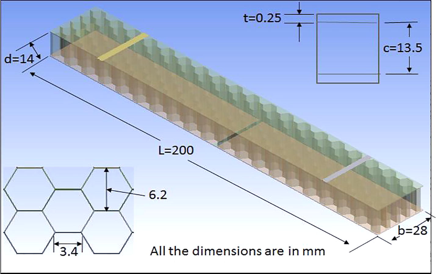
Geometrical dimensions of the honeycomb sandwich panel.
Properties
Core
Aluminum 5052-H32Face sheet
Glass fiber
Poisson’s ratio
0.33
0.125
Density
83 kg/m3
0. 47 kg/m2
Elongation (%)
13
4.8
Tensile Modulus (GPa)
70.3
20
Compressive Strength (MPa)
5.67
467
Compressive Modulus (GPa)
1.31
17
Shear Strength (MPa)
0.68
1.35
Shear Modulus (MPa)
565
30,000
2.2 Experimental procedure
The experimentation for the investigation of the bending strength and fatigue life is carried out on Material Testing System (MTS-810) using three point bending load configurations. In static test the displacement control load is applied and load and mid span deflection were recorded till the failure of specimens. Two specimens are tested for this purpose. The experimental setup and loading configuration according to the ASTM C-393 (C393 and C393M-11, 2012) is shown in Fig. 2. In fatigue testing the samples were loaded with several constant amplitude sinusoidal loads at 3 Hz frequency and load ratio (ratio of minimum to maximum applied load) of 0.1. For each force controlled excitation the beam deflection is recorded. The sudden increase in deflection after the thousands number of cycles is considered the specimen failure. Total fourteen specimen, two for each loading level are tested for the investigation of fatigue life.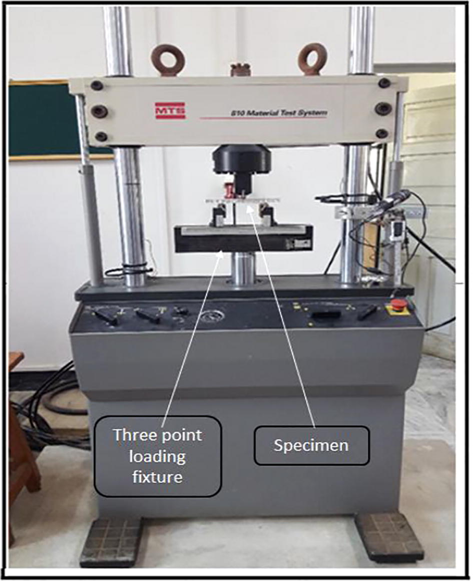
Experimental setup and three point loading arrangement.
To analyze the failure modes only the defective/loaded region of specimens were examined through SEM. Sputter coater was used to make the glass fiber skins conductive by coating with thin metallic gold layer.
3 Finite element analysis
Based on experimental procedure the fatigue life model for honeycomb structure was established. The finite element method was applied to investigate the load-displacement behavior of specimen. FE code ANSYS (ANSYS, 2017) was employed for simulation. For this purpose the three dimensional model of honeycomb designed in Pro/Engineer software is imported in the ANSYS design modeler to carry out the structural analysis. To meet the three point bending requirements bodies for supports and loading were added. After the import of geometry in ANSYS Mechanical the local fine mesh model is generated using body sizing of 3 mm for honeycomb and 4 mm for face sheets. The final mesh was generated with 130,412 nodes and 56,590 elements as shown in Fig. 3. Both honeycomb and face sheets were modeled with tetrahedron elements using patch confirming method structure having 9 nodes with six degrees of freedom at each mode. The orthotropic properties of facing and core used as input are listed in Table 2. All properties of materials are considered elastic plastic. The three point bending load is applied at the mid of specimen with type force in global y direction to investigate the force and mid span displacement behavior of the panel at selected loading region according to the ASTM standard C-393. The high stress concentration places are assumed to be most likely areas where fatigue failure occur in engineering. In solution direct optimization technique was used. In optimization objective the minimum life was selected and magnitude of load was designated as domain parameter. Optimization was performed using seek target method and target constraint was below upper bound. Upper bound value for objective parameter was selected as 1 cycle. The optimization was run and the target was achieved to investigate the maximum load carrying ability of panel. This load was considered the ultimate static load. For fatigue testing of the panel several loading levels were selected from the ultimate static load and life of panel for each load level is recorded.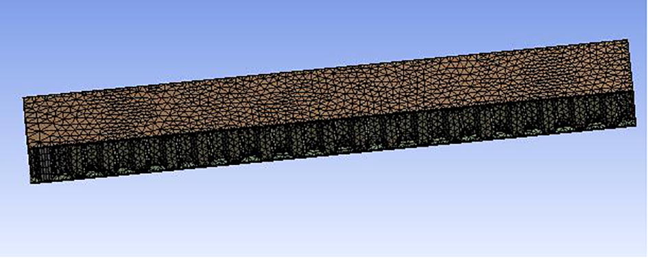
Meshing geometric model.
Behavior of the displacement and load.
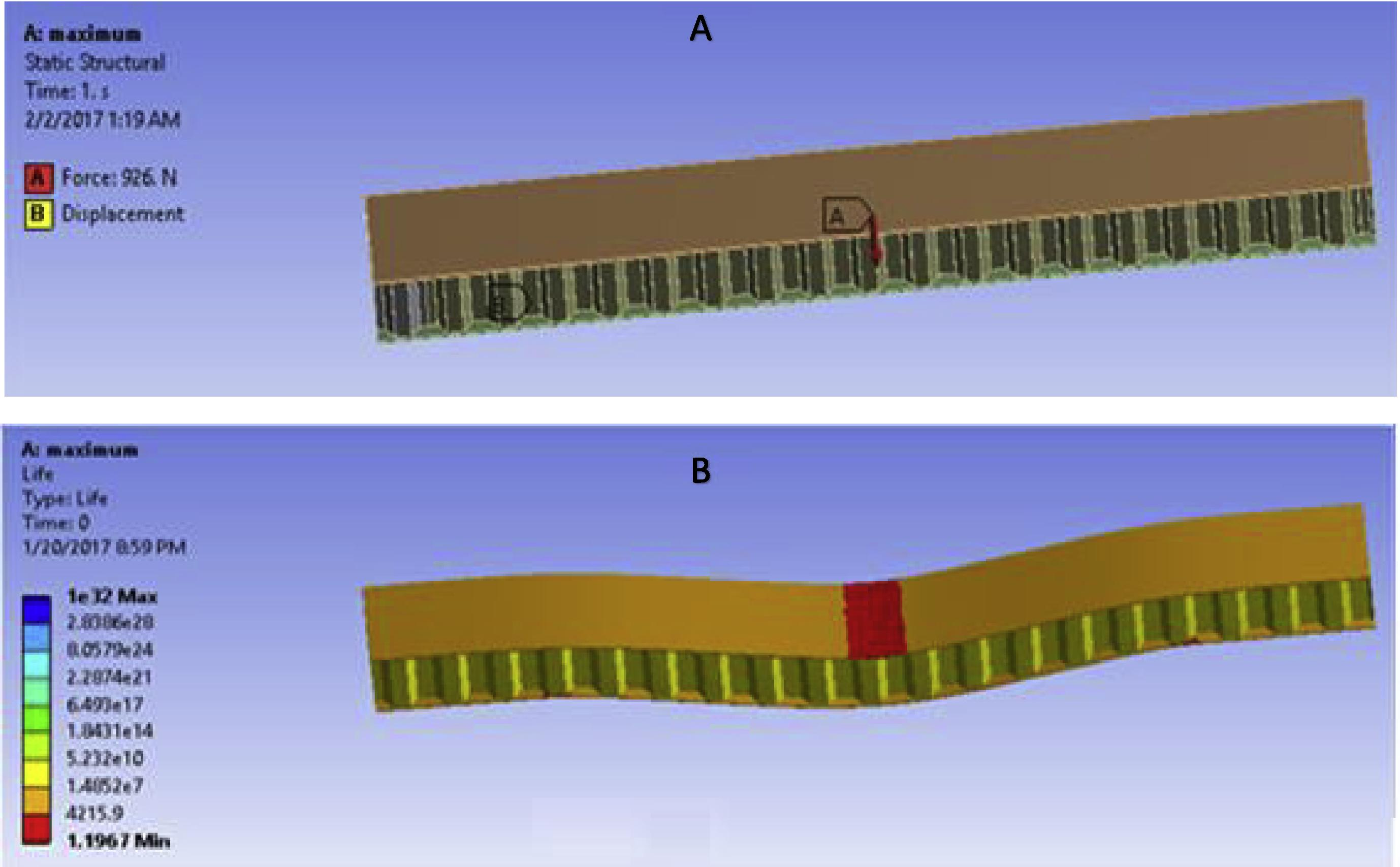
Determination of ultimate strength of the panel. (A) Maximum Force (B) Number of cycles at 926 N load.
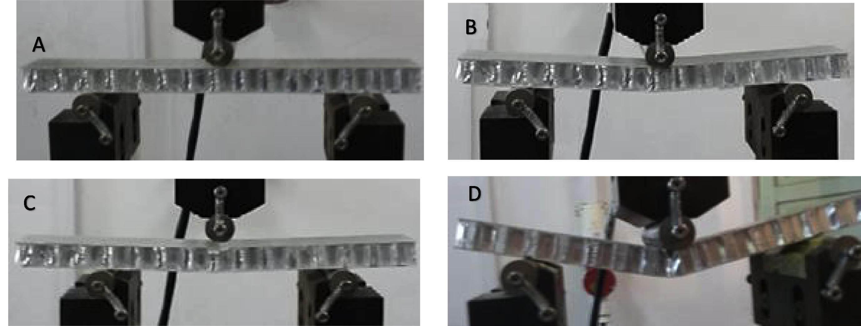
Several phases under static tests (A) specimen under load (B) Face yielding (C) Compression of face sheets (D) Inter laminar shear failure of facing and bending of cell wall.
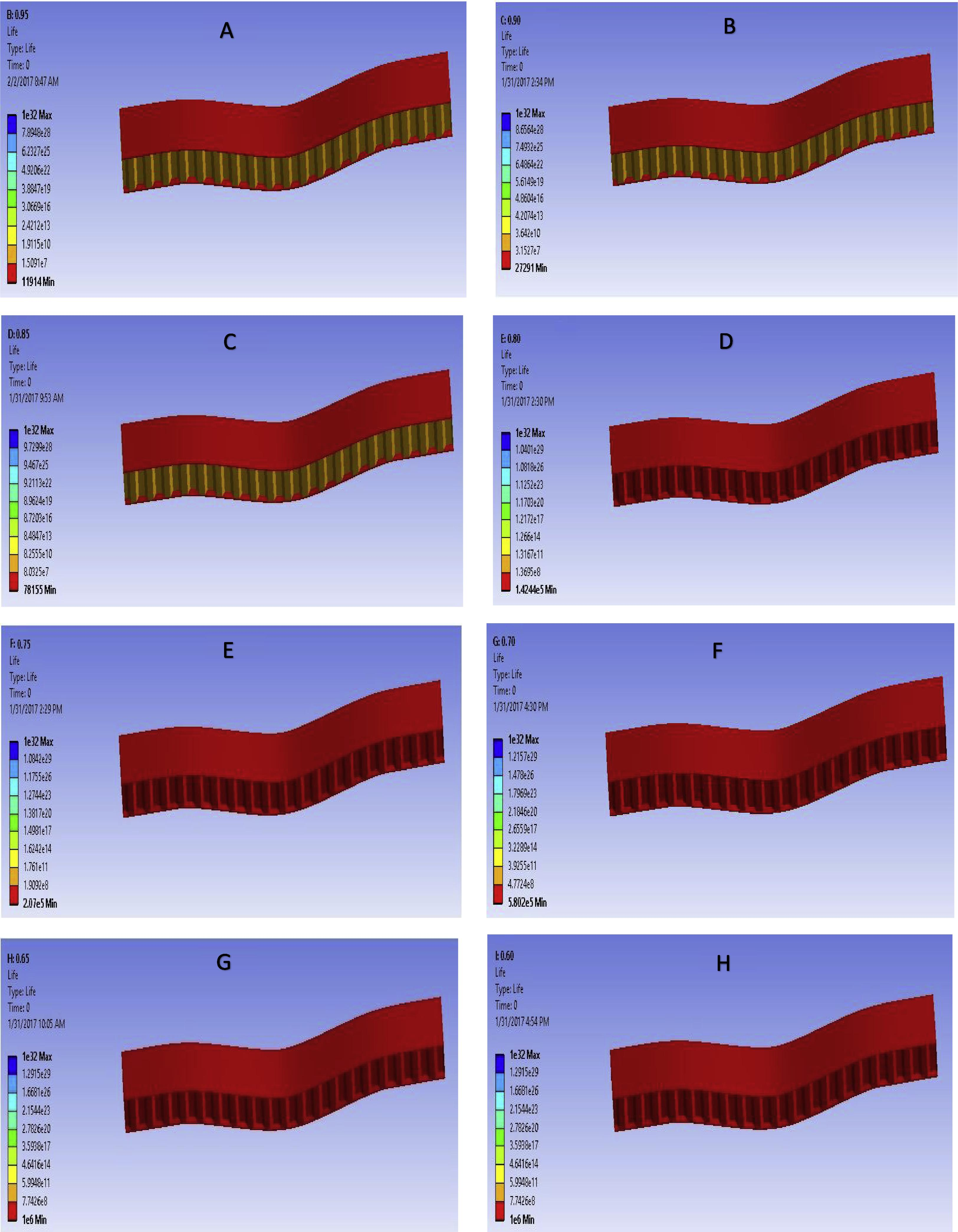
Fatigue life of the panel at several loading levels from 0.95 to 0.60 (A) at 879 N load, (B) at 833 N load, (C) at 787 N load, (D) 740 N load, (E) 694 N load, (F) at 648 N load, (G) at 601 N load, (H) at 555 N load.
Parameter
Honeycomb
Face sheet
Material
Aluminum
Epoxy Glass Fiber
Density
83 kg/m3
2600 kg/m3
Ex
1.48 MPa
12173 MPa
Ey
0.49 MPa
11303 MPa
Ez
2125 MPa
7291 MPa
νXY
0.58
0.18
νYZ
0.000075
0.4
νXZ
0.00024
0.18
GXY
0.72 MPa
4934 MPa
GYZ
253 MPa
2149 MPa
GZY
524 MPa
4934 MPa
4 Fatigue life prediction
Ultimate static load and maximum cyclic load is used for evaluating static and fatigue data respectively. The bending stress (Jen and Chang, 2008) of sandwich panel due to the any applied load with in the span is expressed as:
here b, c and t are geometrical dimension as shown in Fig. 1. S-N fatigue data can be collected using actual loading application between σmax and σmin.
In ANSYS following relation is selected to relate the endurance limit (σe) and ultimate strength (σu) with σm and σa.
Basquin proposed an equation to generate the S-N curve for less than 106 number of cycles.
where a and b are materials constants and can be calculated using σa = 0.95σu at N = 104 and σa = σe at 106 number of cycles. Then
The S-N curve in terms of applied fatigue load and load ratio is given in Fig. 8.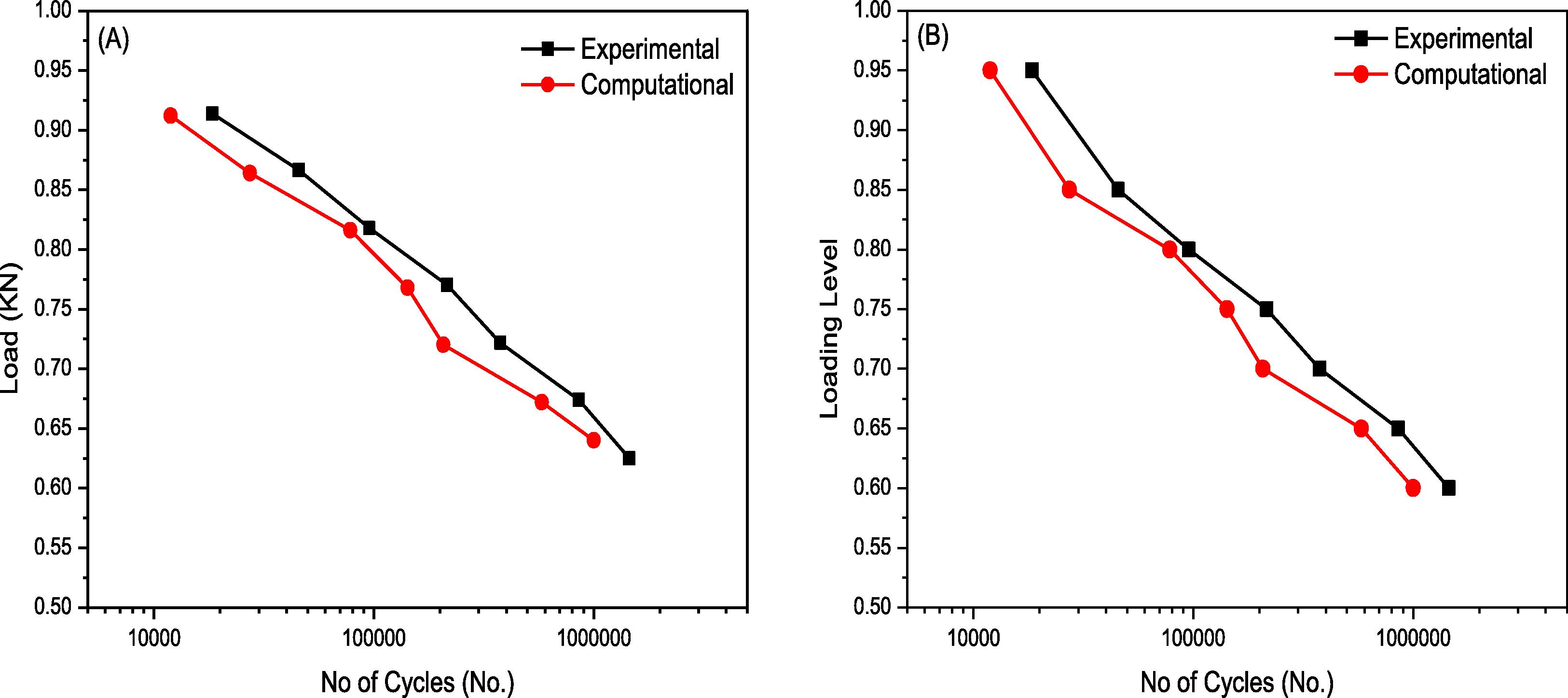
Fatigue testing results (A) load versus number of cycle response (B) Loading Level (Ratio of ultimate static load and applied fatigue load) versus number of cycle response.
5 Results
5.1 Static test results
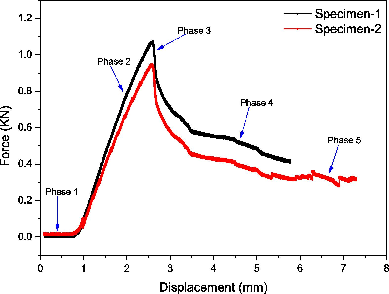
The displacement control loading is applied for the determination of bending strength of the panel. The load and mid span deflection is recorded in hysteresis as well as numeric form. The load and deflection are indicated in five different phases as shown in Fig. 4. The small deflection under very small (negligible) load is shown in phase 1. The increase in deflection causes the face yielding as shown in phase 2. Sudden drop in load carrying ability of panel is due to the indent shown in phase 3. Phase 4 show the little stabilization panel after the failure. The increase in displacement as shown in phase 5 is the result of further application of loading. However in ANSYS the fatigue life of panel at several loading levels was investigated to find the force at which the fatigue life of panel is only one number of cycle. The results are shown in Fig. 5. It was investigated that the experimental average strength of the panel is 963 N and through simulation it was found 926 N as indicated in Fig. 5(a). The closeness of results show the authentication of method of simulation. From the experimental and numerical results it is concluded that the specimens fail due to the indentation as shown in Figs. 5(b) and 6(c).
5.2 Fatigue test results
The fatigue tests were carried out to determine the fatigue life of panel. Fatigue loading levels were selected from the ultimate strength of the panel. In experimentation fatigue deflection along the number of cycle at constant amplitude fatigue loading level is recorded. Under fatigue loading, deflection at mid span remains constant in start and then increase abruptly. The small variation in deflection due to the face yielding or delamination of core and skin interface is considered the stiffness degradation of the panel. The point where the abrupt variation in deflection due to the indentation recorded is considered cycles to failure. In structural analysis of specimen using the ANSYS the fatigue life of panel is recorded at each loading levels as shown in Fig. 7. The fatigue testing results for the investigation of fatigue life of panel as well as for the comparison of numerical and experimental result are given in Fig. 8. It was found that fatigue life decreases with load level. The closeness in experimental and finite element method (ANSYS) results indicates that the FEM is also useable for the investigation of fatigue life. The relative error between experimental and simulation is given in Table 3.
Load level
Experimental results (Numbers)
Simulation results (Numbers)
Errors (%)
0.95
18,449
11,914
35.4
0.90
45,570
27,291
40.1
0.85
95,500
78,155
18.2
0.80
215,000
142,440
33.7
0.75
375,000
207,000
44.8
0.70
856,000
580,200
32.2
0.65
1,450,000
1,000,000
31.0
0.60
–
1,000,000
–
5.3 SEM analysis
The visual analysis show that failure of honeycomb sandwich structure is due to the indentation. However complete analysis using the SEM is conducted to verify and identify the more failure modes during complete procedure of testing. The surface study of face sheet at 232 X magnification confirm the indentation at loaded region as shown in Fig. 9(A). At high magnification 868 X, the breakage of inter lamina of fiber glass face sheet is found due to the compression of facing and indentation as shown in Fig. 9(B). It is found that at low fatigue load level failure initiates due to delamination of core and facing which leads to the interfacial shear failure as shown in Fig. 9(C) and (D) respectively. The increase in load from compressive strength of structures produces defects such as bending and shear failure of honeycomb cell wall as shown in Fig. 9(E) and (F).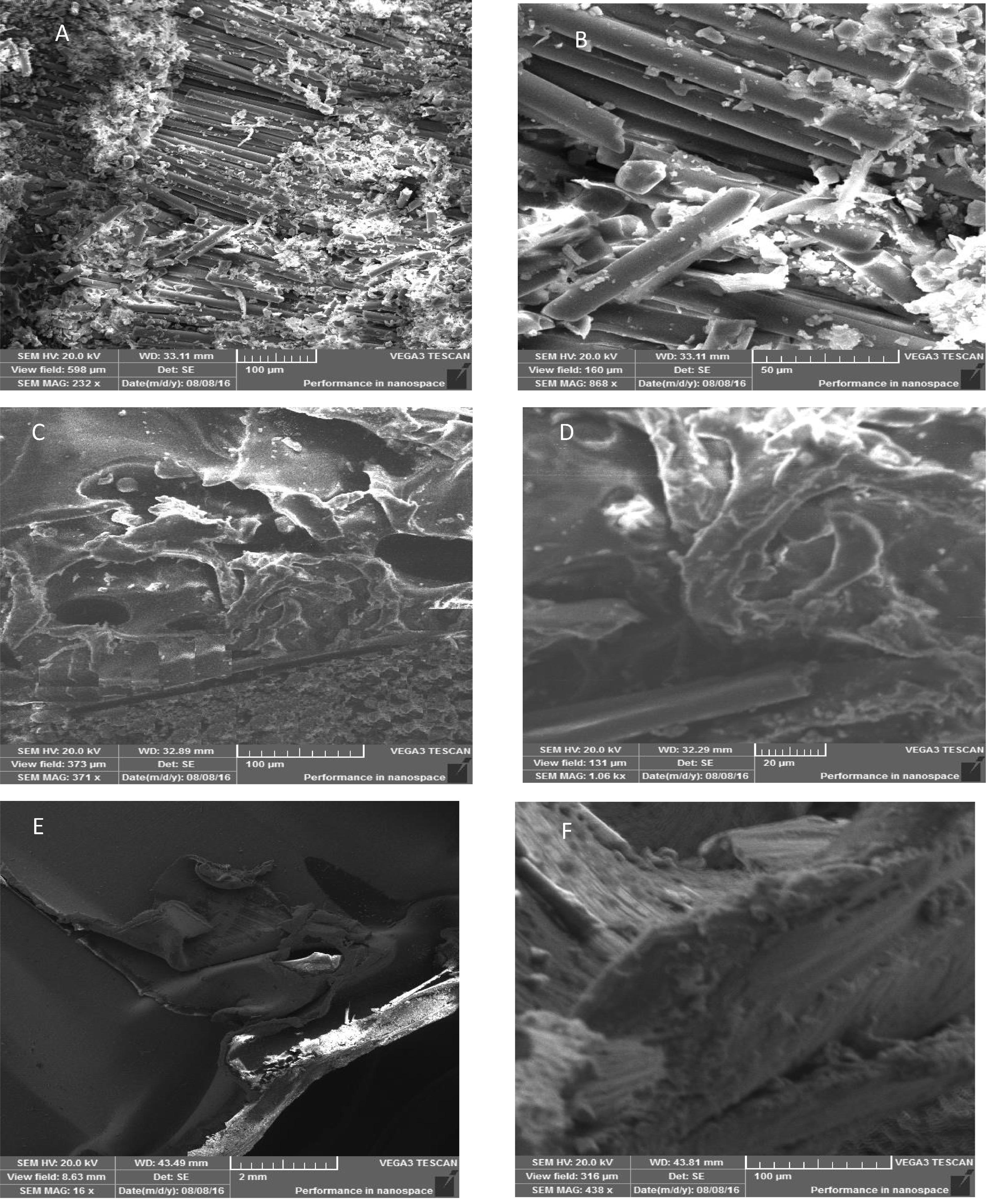
Surface study of face sheet, core and facing interface and cell wall (A) Compression failure of facing at loaded region (B) Failure of inter lamina of fiber glass facing (C) Delamination at core and facing interface (D) Interfacial shear failure (E) Bending defects in core (F) shear failure of cell wall.
6 Discussion
Under static loading, little deflection in presence of negligible load is due to the elastic response of structure. The load carrying ability of panel increases approximately linear until ultimate load due to the compressive and bending stiffness of core. The increase in deflection during the linear increase of load is due to the face yielding. Sudden drop in load carrying ability of panel is due to the indentation with in the span. The little stabilization of panel after the failure is due to the shear resistance of core. The several defects in honeycomb such as bending and share failure of cell wall is the result of further application of load. Hence it is concluded that the specimens failed due to the indentation at the loaded area as shown in Fig. 6. In ANSYS the red color shows the defective part of the specimens. Static test result shown in Fig. 6(b) show that the specimen failed due to the failure of the face sheet with in span. So it is investigated that the Finite element model is not only used to determine the flexural strength of the specimen it is also used to predict static failure behavior of the specimen.
Fatigue testing was carried out at different load levels by keeping amplitude of each cyclic load constant. The deflection at mid span remains constant in start until the little variation is observed up to the thousands of cycles. This small variation in deflection due to the face yielding or delamination of core and skin interface is considered the stiffness degradation of the panel. The point where the abrupt variation in deflection due to indentation is considered number of cycles to failure. Hence in higher loading levels the initiation of fatigue failure is assumed due to face yielding, however in lower loading levels it is due to the interfacial delamination which leads to the indentation. With little reduction in load level, life of panel increases many times. Therefore, approximate 0.60 loading level is recommended for optimal fatigue performance of honeycomb structures. The FEM results also show the sharp increase of fatigue life with the increase of load level. And it can also observed from the Fig. 7(A–C) that at higher loading level the failure of specimen is due to the failure of face sheet. However at lower loading level the failure of specimen is due to the failure of both core and face sheet as shown in Fig. 7(D–H). Indentation is observed more common failure of all panels which can be visualize during loading. However inter shear failure of facing & cell walls, and delamination at core and face interface is examined in SEM analysis.
7 Conclusion
The finite element modeling using the commercially available software is performed for the investigation of static and fatigue performance of honeycomb sandwich structure. The results were compared with the experimental results. The good agreement in both type of results show that the model is suitable for the investigation of flexural strength, fatigue life and failure modes of specimen under static and fatigue load. The FEA method is suitable from the experimental setup because it may be used for the comparison of static and fatigue performance of several types of honeycomb structure by changing the parameters of materials. However the accuracy of results cannot be verified from the simulation itself. The results may be improved by improving the geometric design, meshing, element type, boundary conditions etc.
References
- Experimental study on the fatigue behaviour of honeycomb sandwich panels with artificial defects. Compos. Struct.. 2015;120:394-405.
- [CrossRef] [Google Scholar]
- ANSYS, 2017. Introduction to Ansys for release 18.0.
- Failure mechanism of sandwich beams subjected to three-point bending. Compos. Struct.. 2015;133:739-745.
- [CrossRef] [Google Scholar]
- Identification and prediction of cyclic fatigue behaviour in sandwich panels. Measurement. 2014;53:161-170.
- [CrossRef] [Google Scholar]
- Analysis of structural performance of sandwich plates with foam-filled aluminum hexagonal honeycomb core. Comput. Mater. Sci.. 2009;45:658-662.
- [CrossRef] [Google Scholar]
- Standard test method for core shear properties of sandwich constructions by beam flexure 1. ASTM Int. 2012
- [CrossRef] [Google Scholar]
- Fabrication, testing and analysis of composite sandwich beams. Compos. Sci. Technol.. 2000;60:2455-2463.
- [CrossRef] [Google Scholar]
- Failure modes of composite sandwich beams. Int. J. Damage Mech.. 2002;11:309-334.
- [CrossRef] [Google Scholar]
- Optimal design of a honeycomb core composite sandwich panel using evolutionary optimization algorithms. Compos. Struct.. 2016;139:254-262.
- [CrossRef] [Google Scholar]
- Experimental and numerical research on the low velocity impact behavior of hybrid corrugated core sandwich structures. Compos. Struct.. 2016;158:30-43.
- [CrossRef] [Google Scholar]
- Design and testing of sandwich structures with different core materials. Mater. Sci.. 2012;18:45-50.
- [CrossRef] [Google Scholar]
- Investigation of static and fatigue behavior of honeycomb sandwich structures under bending load. Tech. J. Univ. Eng Technol. Taxila, Pak.. 2017;22:72-80.
- [Google Scholar]
- Evaluating bending fatigue strength of aluminum honeycomb sandwich beams using local parameters. Int. J. Fatigue. 2008;30:1103-1114.
- [CrossRef] [Google Scholar]
- Sandwich structured composites for aeronautics: methods of manufacturing affecting some mechanical properties. Int. J. Aerosp. Eng.. 2016;2016:1-10.
- [CrossRef] [Google Scholar]
- Fatigue life assessment of centrifugal compressor impeller based on FEA. Eng. Fail. Anal.. 2016;60:383-390.
- [CrossRef] [Google Scholar]
- Dynamic behaviour of soft core sandwich beam structures using kriging-based layerwise models. Compos. Struct.. 2015;134:883-894.
- [CrossRef] [Google Scholar]
- Post-wrinkling behavior of webs in GFRP cell-core sandwich structures. Compos. Struct.. 2016;138:276-284.
- [CrossRef] [Google Scholar]
- Geometrically nonlinear analysis of sandwich structures. Compos. Struct.. 2016;156:135-144.
- [CrossRef] [Google Scholar]
- Experimental and modelling study of low velocity impacts on composite sandwich structures for railway applications. Eng. Fail. Anal.. 2016;68:22-31.
- [CrossRef] [Google Scholar]
- Finite element analysis of traction gear using ANSYS. Mater. Today:. Proc.. 2015;2:2236-2245.
- [CrossRef] [Google Scholar]
- An introduction to the finite element method with application to nonlinear problems. Math. Comput 1988
- [CrossRef] [Google Scholar]
- Bending behavior of graded corrugated truss core composite sandwich beams. Compos. Struct.. 2016;138:342-351.
- [CrossRef] [Google Scholar]
- A research on fatigue life of front axle beam for heavy-duty truck. Adv. Eng. Softw.. 2016;91:63-68.
- [CrossRef] [Google Scholar]


