

Evaluation to possibility of cellulose fibers isolated from kapok randu (Ceiba Pentandra) as a precursor growth of carbon micro structures with the assist of metal catalysts
⁎Corresponding author at: Cellulosic and Functional Materials Research Centre, Universitas Sumatera Utara, Jl. Bioteknologi No. 1, Medan 20155, Indonesia. s.gea@usu.ac.id (Saharman Gea),
-
Received: ,
Accepted: ,
This article was originally published by Elsevier and was migrated to Scientific Scholar after the change of Publisher.
Peer review under responsibility of King Saud University.
Abstract
Abstract
Objective
As a hydrocarbon material, cellulose could be used as precursor in synthesizing carbon micro-structure (CMTs), and this study aims to investigate the potential use of cellulosic material from kapok randu as a precursor in synthesizing carbon-based structures.
Methods
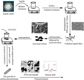
The isolation of cellulose was carried out via alkaline treatment, followed by mechanical disintegration. Meanwhile, the growth of CMTs was performed via heating treatment for 12 h with various catalysts (i.e., Fe, Ni, and Cu). Chemical characteristics were confirmed by FTIR, XRD spectra, while TEM, SEM and Raman spectra were performed to determine the growth of CMTs.
Results
The thermal characteristic suggested that the decomposition was initiated at 300 °C. The FTIR results confirmed the presence of functional groups in accordance to cellulose fiber, such as –OH (3418 cm−1), C—H aliphatic group (2900 cm−1), O—H (1635 cm−1), and C—H (1334 cm−1). Whilst, the FTIR pattern also confirmed the presence of C⚌C stretching at 1600 cm−1, –CH in between 2800 and 3000 cm−1, indicating the activated carbon. Raman shift indicated the growth on G-band in the interval of 1500–1700 cm−1, suggesting the presence of C—C structures. Based on the morphological characteristics, the growth of CMTs were successfully obtained with different diameters and lengths due to the different catalysts used. The iron (Fe) catalysts produced CMTs with a diameter about 200 nm and average length of 2–3 µm, whereas the Ni catalysts formed tubes with around 150 nm of length and 50 nm of diameter. Meanwhile, the Cu catalysts formed amorphous particles with diameter below 10 nm.
Conclusion
From these results, the evaluation of cellulose isolated from kapok randu as a precursor in the growth of carbon micro-tube with distinguished characteristics was demonstrated.
Keywords
Nanofibers cellulose
Activated carbon
Kapok randu
Precursor
Carbon based-structures

1 Introduction
The discovery of carbon-based nanostructures, such as carbon fibers, carbon nanotubes (CNTs), carbon microtubes (CMTs), and carbon nanodots, appears to be beneficial for practical applications. In term of CNTs and CMTs, the structures have similarities particularly in hollow, tubular, and single- or multi- walled which only differ in the size, and since their discoveries (Ijima, 1991). Ever since the discovery, another attempt to produce similar carbon-based structures, such as CMTs is carried out. Both CNTs and CMTs are fabricated by applying certain temperature of treatments which most of them were in high temperatures with high pressure condition. Therefore, the synthesis of CMTs is influenced by three factors i.e., temperature, and to reduce the high temperature, the latter factors are catalysts and the carbon sources. The precursors for synthesizing have become a challenge, which commonly is organic compounds such as methane, methanol and acetone(Janas, 2020). Materials consisted of carbons were the most suitable precursors for synthesizing CNTs and CMTs, including hydrocarbon compounds such as methane(Kang et al., 2008) and ethanol(Kakehi et al., 2008). The drawbacks in using these two types of precursors require high temperatures of treatments even though its gaseous form reduces time reaction. Nonetheless, gaseous phases are not the only substances that could be used as precursors as a study had successfully synthesized CNTs from solid materials(Singh et al., 2002). On the other hand, the needs of carbon microtubes (CMT) for several applications are in needs such as for oil adsorption(Zhao et al., 2019), and batteries and energy storage(Huang et al., 2012);(Salahdin et al., 2022), which are synthesized from solid compounds. Hence, finding strategies via availability of precursors and selective catalyst is promising advantages for future use.
In term of availability, cellulose provide advantages due to their availability of abundant material in carbon content. This organic material is commonly found in plants, for instance, angel’s trumpet plant contains high variation of acidic compounds which also can be precursors for synthesizing carbon-based materials (Mokbli, 2021). Furthermore, In Indonesia, cellulose is organic waste that is annually produced by the plantations, including empty bunch of palm oil, and even more a study utilized part of palm oil tree which is the kernel shell as precursor for bifunctional catalyst (Abdullah et al., 2020). Based on its structure, cellulose has been used as biofuel (Panneerselvam et al., 2016), suggesting its high carbon content. Other reports have also successfully carbon nano- and micro-structures with mesoporous morphological features from paddy rice(Hao et al., 2019), poplar-catkin(Huang et al., 2021), and plant tissues(Zhao et al., 2019). Another potential plants that can be a precursor is kapok randu, which is a native plant to Indonesia. Cellulose fibers from kapok randu were reported to be used in the synthesis of activated carbon(Chung et al., 2013); subsequently; cellulose-fiber from this plan can be used as the precursors in synthesizing CMTs.
Attempts in synthesizing carbon-based microstructures seem to be high-cost due to the use of catalysts in order to overcome the non-steady phase of carbonization. Several reports have suggested the introduction of catalysts, such as silver nanoparticles (Gea et al., 2022) which is considered as high-cost. Whilst, the use of mono-(Co) combined with bimetallic (Fe-Co) catalysts during CVD synthesis is considered as complex strategies which also takes place in high energy(Balogh et al., 2008);(Kakehi et al., 2008). Although several reports have used transitional-metals (TiC, NiCl2, SnO2) and non-metal catalysts (Sulfur) with more controllable reaction, these show limited selection in finding affordable and available catalysts for synthesizing with low-cost aspects(Huang et al., 2021);(Ariyanto et al., Feb. 2019);(Anil Kumar et al., 2022). Hence, the purpose of this present work was to evaluate the possibility of cellulose fibers isolated from kapok randu to be used as the precursor with catalysts such as Fe, Ni, and Cu via heating treatments were.
2 Materials and methods
2.1 Materials
The Kapok Fibers (KFs) were collected from the fruit, in which the tree was located in the sub-district Tanjung Mulia, Deli Serdang Regency, Medan, Indonesia. The chemical reagents such as HCl, NaOH, H2O2, H2SO4, H3PO4, NaOCl, Na2S2O3, NaNO3 and acetone were purchased from Sigma Aldrich Inc. Meanwhile, the metal catalysts, such as FeSO4·7H2O, NiSO4·H2O, CuSO4·5H2O were supplied by Bratachem. The gasses utilized to control the condition including nitrogen, methane, hydrogen and helium, were purchased from supplied by PT Aneka Gas.
2.2 Preparation of cellulose kapok fibers
The amount KF that was from the fruit was separated manually via man-labor. Then, these amounts of fibers were dried directly under daylight, and from these amounts, 75 g of KFs were cut into 2–3 cm of sizes. The fibers were immersed in 1 L of 3.5 % HNO3 and 10 mg NaNO3 mixture for 2 h at 90 °C. Then, the mixture was filtered and the fibers were washed by using distilled water until the neutral pH was achieved. Next, the fibers were soaked into 750 ml of 2 % w/v NaOH and 2 % Na2S2O3 solution for 1 h at 50 °C, and followed by washing and filtrating processes. Afterward, these KF samples were bleached with 250 ml of 1.75 % of NaOCl solution until its temperature boiled for 30 min. After being bleached, the samples were mixed with 500 ml of 17.5 % NaOH for 30 min at 50 °C to obtain cellulosic sample. Then, this cellulosic sample was washed by using distilled water, in which hereafter, 10 % of H2O2 were used to immerse the samples for 30 min at 60 °C. The cellulosic sample then was filtered and dried in an oven at 60 °C to remove the residual water content, which was followed by storing it in a desiccator.
2.3 Isolation of nanofiber cellulose kapok fibers
The first step in isolating nanofiber cellulose (NFC) from KFs began by acid hydrolysis treatment, which was previously described in several studies(Gea, Panindia, et al., 2018; Gea, Zulfahmi, et al., 2018; (Zulham Efendi Sinaga et al., 2018). The cellulosic fibers were soaked in 45 % H2SO4 with ratio of 1:25 w/v% for 45 min at 45 °C. Then, into the mixture, some bi-distillation water with ratio 1:25 v/v% were added and the mixture was allowed to stand for 12 h at room temperature to form suspension. The suspension was separated and washed to reach pH 7. Next, this mixture sample was placed in an ultrasonic bath for 3 h, and then followed by homogenization step for 3 h at 8000 rpm. Finally, these nano-cellulosic kapok fibers (NCKFs) were heated at 50 °C in an oven to remove water content, and the dried samples of NCKFs were obtained which hereafter is stored in desiccator.
2.4 Thermal gravimetric analysis
The characterization of TGA was performed to determine as basis of later heating treatments for the growth of CMT. The TGA was carried out via TGA DTG-60 in which the thermal rate was 10 °C.min−1 in nitrogen condition (flow rate 30 ml.min−1). The initial temperature was 27 °C, and final temperature was 600 °C, whereas the starting mass of the NCKFs was 3 mg.
2.5 Synthesis of activated carbon from NCKFs
Thermal Gravimetric Analysis (TGA) was used to obtain the decomposition temperature. The decomposition process started at 320 °C based on the TGA result, so that the NCKFs were heated inside a furnace at 400 °C for two hours to produce carbon. Afterward, the carbon samples were obtained, and the chemical activation were performed by immersing these carbon samples into 1 M H3PO4 for 90 min with ratio 1:10 w/v%. Then, this mixture was filtered, and the filtered carbon samples were dried at 150 °C for 24 h. Afterwards, 5 N HCl was added to the dried carbon samples to perform reactivation. Thus, the removal of excessive chloride ions was done by washing these dried carbon samples with distilled water to reach pH 7, and followed by additional washing with cool distilled water as well as filtering to remove the residual of phosphate anion. After being washed and filtered, the wet carbon samples were dried at 150 °C for 24, and finally this sample was named after AC.
2.6 Synthesis of carbon microtubes from AC with various catalysts
2.6.1 The preparation of catalyst- solutions
The preparation of 0.09 M Cu(NO3)2, 0.09 M Ni(NO3)2, and 0.09 M FeCl3 catalyst solutions was carried out by respectively dissolving 1.08 g of Cu(NO3)2·3H2O, 1.3 g of Ni(NO3)2·6H2O, and 1.21 g of FeCl3·6H2O in acetone. Then, each solution was homogenized with constant stirring.
2.6.2 The impregnation of Ni/Cu/Fe catalysts
The preparation of catalysts for CMTs was performed by mixing 0.09 M Cu(NO3)2, 0.09 M Ni(NO3)2, and 0.09 M FeCl3 with AC and ratio of 1:10 w/v%. Then, each of the mixture underwent ultrasonication for 2 h at 70 °C. The results of the impregnation samples were dried in oven for 12 h at 70 °C.
2.6.3 The growth of carbon microtubes (CMTs)
An amount of impregnated AC samples was placed in a 25 ml porcelain dish into a gas furnace. On the surface of the dish, the end of furnace ceramic pipe was connected to gas source. During the heating process, the dish was covered to prevent small carbon particles from escaping. The first step was calcination process, which was done by streaming the impregnated AC with heat at 500 °C for two hours under inert conditions (nitrogen gas 100 ml.min−1). The second stage was a reduction process, where the temperature of 700 °C and hydrogen gas (with flow of 60 ml.min−1) were applied for two hours. In this process, metal oxides would be removed and the metals were converted into metal nanoparticles. In the third stage, the temperature in the reactor was increased to 950 °C, and followed by the increase of nitrogen gas rate to 100 ml.min−1. When the reactor reached the set temperature, the nitrogen gas rate was increased to 200 ml.min−1. The next stage was the flowing of mixture methane and nitrogen gas which respectively 1:2 ratio (rate of 100 ml.min−1) for two hours at 950 °C. Then, at the final process, Helium gas was flowed at 60 ml.min−1 into the furnace, thus; the temperature within it would drop to room temperature. Inert condition during the final process was important in order to prevent the destruction of CMTs.
2.6.4 Characterization of carbon microtubes (CMTs)
In this research, CMTs were analyzed by Transmission Electron Microscopy (TEM) instrument (JEM-1400) with acceleration voltage 120 kV. The photograph obtained from TEM was analyzed to observe the length and diameter of the tubes via Image-J application, as well as the structures of CMTs, which were different, depends on the catalyst used.
3 Results and discussion
3.1 FTIR and morphological characteristics of NCKF
The NCKF were analyzed by Fourier Transform Infrared (FTIR) instrument. Characterization by FTIR was done to confirm the functional groups in NCKF in Fig. 1.
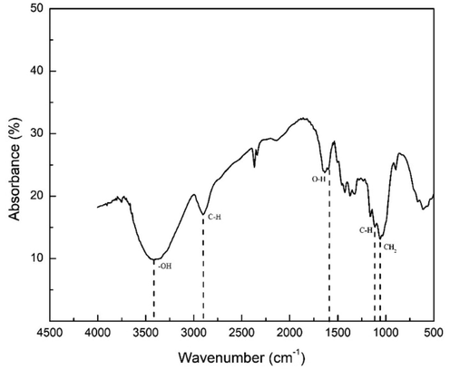
- FTIR Pattern of Cellulose Fibers Isolated from Kapok Randu.
The FTIR pattern shows that the functional groups of the NCKF were the same as cellulose fibers. The –OH functional group was shown at peak 3418 cm−1 with stretching vibration up to 2900 cm−1, whereas, the C—H aliphatic group was at 2900 cm−1. It could also be clearly seen that the O—H group related to carboxylate group was at 1635 cm−1. The bending vibrations of H—C—H, O—C—H, and C—H, and rocking vibration of –CH2 were respectively at 1427 cm−1, 1373 cm−1, and 1334 cm−1, which these three vibrations were in C6 glucose chain. The Fig. 2 shows the morphological of NCKF.
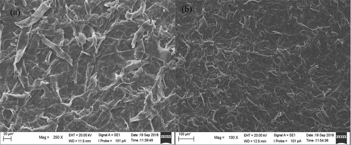
- SEM Photographic Image of NCKF (a) 250 times magnification, and (b) 100 times of magnification.
Fig. 2 shows morphological images by SEM of NCKF obtained with 250 and 100 times of magnification. Unlike those obtained by previous studies, the NCKFs had different shapes from palm oil bunches and corncobs (Zulham Efendi Sinaga et al., 2018). Although generally, kapok randu is one of tropical tress with fruits containing cellulosic fibers, its cellulosic material has been reported to be hydrophobic-oleophilic (Wang et al., 2018). Hence, it is assumed that the thermal properties of NCKF were different due to its utilization as a precursor in the synthesis of CMTs.
3.2 Thermal gravimetric analysis of NCKF
As the NCKFs was used as the precursor to synthesize CMTs, TGA analysis was performed to determine the temperature breakdown. The Fig. 3 depicts the comparison of TGA analysis of NCKFs.
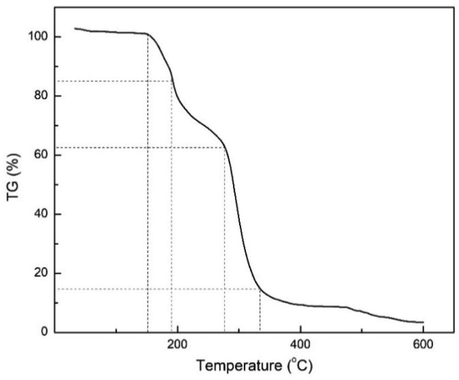
- TGA Analysis of NCKFs.
According to Fig. 3, the initial temperature started from 27 °C to 600 °C, and the initial mass of NCKFs was 3 mg with 10 °C.min−1 of heating rate. The significant observation can be seen at the temperature above 300 °C as the NCKFs started to decompose and reached 60 % of mass change. Although the NCKFs differs to other biomass, this thermal analysis has confirmed similar data to what have been reported in several studies (Soykeabkaew et al., 2012). The region of initial and ending composition were above 300 °C and 600 °C respectively (Gea et al., 2020a).
As it has been reported by several studies, around 32–47 % cellulose was isolated from various raw materials (Gea, Andita, et al., 2018; Gea et al., 2020a; (Marpongahtun et al., 2018), where its physical and chemical structures may have been different from one to another due to different alkaline treatments. The use of sodium hydroxide in cellulose isolation has been concluded to provide distinguishing impacts on the morphological structures, including the stiffness and orientation of the fibrils (Chakraborty et al., 2011).
3.3 FTIR spectra of activated carbon (AC) from NCKF
In this study, the AC was obtained from NCKFs, and in Figs. 2 and 3, the –OH, C—H aliphatic, and –CH2 were confirmed. However, the spectrum of AC in Fig. 4 showed different results, particularly in the presence of new groups and the occurrence of reduction. The groups, such as C⚌C, C—O, and P = OOH was confirmed due to the treatments with H3PO4. This could occur as the surface of biomass was carbon-derived(Oginni et al., 2019), which were indicated the presence of C⚌C stretching band around 1600 cm−1, –CH stretching band in interval of 2800–3000 cm−1, and -P = OO4 in 1100 cm-1(Xu et al., 2014).
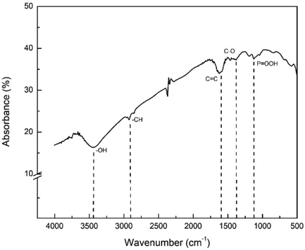
- FTIR Spectra of Activated Carbon from NCKF.
Subsequently, the confirmation of activated carbon was also performed to ensure the success synthesis. The following Fig. 5 demonstrates the XRD result of sample activated carbon. In overall, two broad peaks were noticeable observed in 40-50° and 60-70° which is related to (0 0 2) (Xu et al., 2014). It also can be observed that amorphous parts of activated carbons alongside, in which it could have attributed to the random stacking of layers, that were also noted from the SEM photographic images in Fig. 5 (inset).
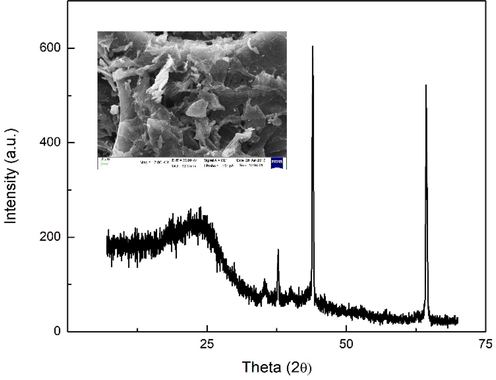
- XRD pattern of activated carbon with SEM image of activated carbon (inset).
3.4 TEM analysis of CMTs from NCKFs
Fig. 6 shows significant differences of TEM photographic images in each sample synthesized from different catalysts. The commercial AC samples were with diameter of 45–50 nm (Fig. 6a). The image also showed metal nanoparticles attached to the cap of the CMTs with a mean tube length of 600 nm. Meanwhile, the sample with AC synthesized from NCKF with Cu catalyst for 11 h had tube diameter and length of 50 nm and 100 nm respectively (Fig. 6c). In Fig. 6c*, with samples made of Cu catalyst, produced mostly spherical amorphous carbon particles with sizes of under 10 nm. Meanwhile, the AC from NCKF with Ni catalyst had tube diameter and length about 40–50 nm (Fig. 6d).
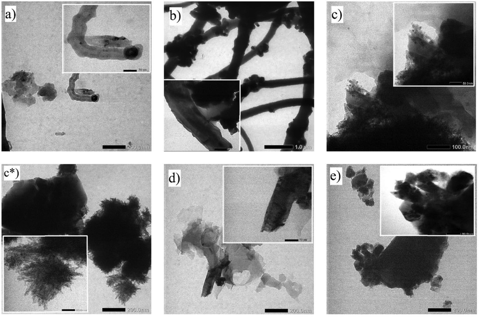
- TEM Photographic Images of Prepared Samples. a) Commercial CNT; b) CNT activated carbon catalyst/Fe 6 h; c, c*) CNT activated carbon catalyst/Cu 11 h; d) CNT commercial active catalyst/Ni 11 h; e) CNT activated carbon catalyst/Ni 11 h.
The first variation was sample of AC from NCKF with Fe catalyst treated for 6 h to produce CMTs with diameters of 200 nm with the average tube length of 2–3 µm (Fig. 6b). Then, the second variation was commercial AC with Ni catalyst treated for 11 h, produced CMTs with diameters of 50 nm and a tube length of 150 nm (Fig. 6e). This happened due to the solubility of carbon in metal particles, which would form solid filaments alongside with the width of the diameters(Duc Vu Quyen et al., 2019). Another report has shown that the decreasing of diameter of CMTs from kapok randu for almost a half (from 20 µm to ∼ 12 µm) after carbonization at the temperature of 500–1000 °C(Zhao et al., 2019). Fig. 6a and 6b display tubular structure even though rough shapes were found. Therefore, high temperature used could reduce catalyst activities to bind the carbons in CMTs arrangement during the reaction, such as direct calcination at 500 °C(Wang et al., 2018). It is assumed that due to the high temperatures that leads to high pressure condition, carbon atoms begin to degrade and create uncontrollable reaction, which allows the formation of carbon clusters. At the same time, the surface of AC could react to which form graphitization too, and due to the use of the metal catalysts which implied to the uncontrollable graphitization reaction(Ariyanto et al., Feb. 2019). The reaction caused the particles to agglomerate to each other, so that the reaction results tended to lead the formation of amorphous carbon particles with a size below 10 nm(Ahmad et al., 2018) as it is shown in Fig. 6.
In general, the synthesis reaction of CNTs via CVD was carried out over a time span of 30–60 min for the growth of CNTs by using precursors(Costa et al., 2008);(Ramírez Rodríguez et al., 2018). Several studies also mentioned that the process could take longer time(Li et al., 2009);(Fathy, 2017). In this study, the results obtained based on TEM analysis showed a small amount of pile up (especially based on Fig. 6a and b), which was assumed to occur due to thermal treatments. However, the tubes produced in this study were seen to be consistent compared to previous reports(Duc Vu Quyen et al., 2019);(Ahmad et al., 2019). The optimum growth of CMTs was 30–60 min, more than 60 min would not produce more CMTs as the surfaces of catalyst would have been overgrown with CMTs. In conclusion, the use of a longer time with the same temperature would reduce the yield of CMTs as previously reported (Ahmad et al., 2019).
3.5 Raman spectra of prepared samples from AC-NCKF
The above Fig. 7 is the Raman shifts of pyrolysis sample of AC from NCKF with different catalysts, i.e., the impregnation of Ni, Fe, and Cu. The shifting could be clearly seen in the interval of 1500–1700 cm−1, indicating the first order of G band as well as implying the presence of C—C structures. Among three of them, sample 1 and 2 had the higher intensity, and also, in Fig. 7B, the sample 2 which was treated with Cu as the catalyst, had higher intensity counts than that in sample 1 that was treated by Fe as the catalyst. The presence of this peak has confirmed the successful growth of single-wall carbon nanotube (SWCNT); as per what other studies have also reported the shifting 1500–1700 cm−1 both in red and green laser (respectively 785 and 514 nm)(Costa et al., 2008);(Li et al., 2009).
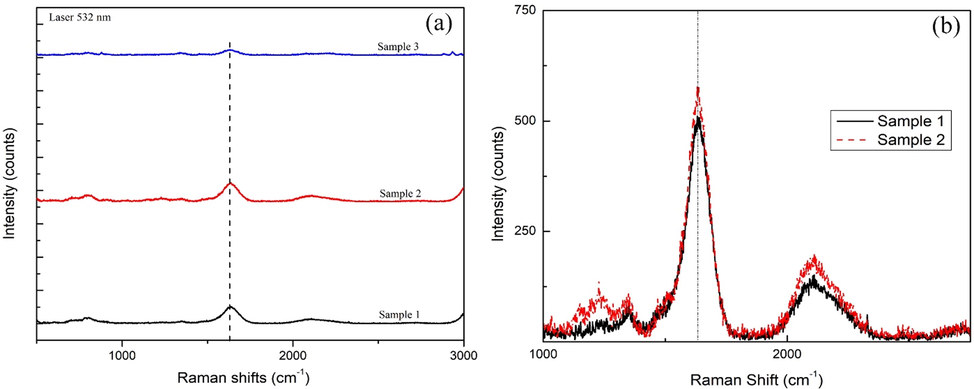
- Raman Shifts of CMT Sample from kapok randu (a). The comparison of sample 1 (catalyst Ni), sample 2 (catalyst Fe), and sample 3 (catalyst Cu); (b). Specific Shifting for Sample 1 (Ni) and Sample 2 (Fe).
Metal catalysts, mono-metals in particular, could affect the structural rearrangement structure of the carbonaceous materials(Ahmad et al., 2019). As this study only focused in the use of mono-metals, the selection of metals was based on the precursor, which is the cellulosic material(Duc Vu Quyen et al., 2019);(Ahmad et al., 2019). Both TEM and Raman results confirmed the differences in each growth samples in terms of the sample intensities as well as the length of the tubes. Copper (Cu) catalysts had amorphous structures, which were both proven by sample 3 in Raman shift results (Fig. 7a). These results were in accordance to the studies which utilized Fe and Ni catalysts, producing long-shape tube growths via CVD method(Arjmand et al., 2016). Meanwhile, another research reported Ni catalyst has successfully synthesized long-shape tubes with 10–40 nm diameters via microwave treatments(Burakova et al., 2018). Although this study investigated that sample Cu and Ni which are based on Fig. 6a, 6b, and 6d, the growth of the tubes via AC from NCKF may occur due the surface area. Thus, it is suggested to evaluate further about the relation of surface area with the growth of carbon microstructure, nevertheless; have been successfully obtained.
4 Conclusion
The fibrous material from kapok randu that contains cellulose has the potential to be precursors for CMTs synthesis from activated carbon as the basis of growth. By using various catalysts, such as iron, nickel and copper, the growth of CMTs has been successfully obtained via thermal treatments with the introduction metal catalysts of Fe, Ni, and Cu at moderate temperature (700–950 °C) even though longer graphitization takes time. Based on the results, the size diameter of the CMTs were in between 50 and 200 nm with length diameter of less than 2 µm in average, as the growth is observed in the micrograph results. The highest presence of CMTs’ growth was observed in sample with nickel (Ni) catalyst, and the Raman shifts appears to show the growth with considerably peaks. Thus, further investigation related to the physical parameters of catalysts and graphitization reaction in moderate temperature is required.
Acknowledgement
The authors would like to thank the rector of Universitas Sumatera Utara as its grants via TALENTA scheme program with given contract No. 2590/UN.5.1.R/PPM/2018.
Declaration of Competing Interest
The authors declare that they have no known competing financial interests or personal relationships that could have appeared to influence the work reported in this paper.
References
- Synthesis of bifunctional nanocatalyst from waste palm kernel shell and its application for biodiesel production. RSC Adv.. 2020;10(45):27183-27193.
- [CrossRef] [Google Scholar]
- Systematic investigation of the catalyst composition effects on single-walled carbon nanotubes synthesis in floating-catalyst CVD. Carbon N. Y.. 2019;149:318-327.
- [CrossRef] [Google Scholar]
- Synthesis of multiwalled carbon nanotubes supported on M/MCM-41 (M = Ni, Co and Fe) mesoporous catalyst by chemical vapour deposition method. J. Porous Mater.. 2018;25(2):433-441.
- [CrossRef] [Google Scholar]
- An efficient and durable bifunctional electrocatalyst based on SnO2/CNT toward electrocatalytic full water splitting. J. Alloys Compd.. 2022;922:166284.
- [CrossRef] [Google Scholar]
- “Improving control of carbide-derived carbon microstructure by immobilization of a transition-metal catalyst within the shell of carbide/carbon core–shell structures”. Beilstein J. Nanotechnol. 10: 41. Feb. 2019;10(1):419-427.
- [CrossRef] [Google Scholar]
- Effect of synthesis catalyst on structure of nitrogen-doped carbon nanotubes and electrical conductivity and electromagnetic interference shielding of their polymeric nanocomposites. Carbon N. Y.. 2016;98:358-372.
- [CrossRef] [Google Scholar]
- CVD-synthesis of multiwall carbon nanotubes over potassium-doped supported catalysts. Appl. Catal. A Gen.. 2008;344(1-2):191-197.
- [CrossRef] [Google Scholar]
- Novel and economic method of carbon nanotubes synthesis on a nickel magnesium oxide catalyst using microwave radiation. J. Mol. Liq.. 2018;253:340-346.
- [CrossRef] [Google Scholar]
- Adsorption of crystal Violet from aqueous solution onto NaOH-modified rice husk. Carbohydr. Polym.. 2011;86(4):1533-1541.
- [CrossRef] [Google Scholar]
- “Synthesis and characterization of activated hollow carbon fibers from Ceiba pentandra (L.) Gaertn. Mater. Lett.. 2013;93:401-403.
- [CrossRef] [Google Scholar]
- Characterization of carbon nanotubes by Raman spectroscopy. Mater. Sci.- Poland. 2008;26(2):433-441.
- [Google Scholar]
- Carbon nanotubes: synthesis via chemical vapour deposition without hydrogen, surface modification, and application. J. Chem.. 2019;2019:1-14.
- [CrossRef] [Google Scholar]
- Carbon nanotubes synthesis using carbonization of pretreated rice straw through chemical vapor deposition of camphor. RSC Adv.. 2017;7(45):28535-28541.
- [CrossRef] [Google Scholar]
- Preliminary study on the fabrication of cellulose nanocomposite film from oil palm empty fruit bunches partially solved into licl/dmac with the variation of dissolution time. J. Phys. Conf. Ser.. 2018;1116:042012.
- [Google Scholar]
- S. Gea, B. Attaurrazaq, S. A. Situmorang, A. F. R. Piliang, S. Hendrana, and S. Goutianos, “Carbon-Nano Fibers Yield Improvement with Iodinated Electrospun PVA/Silver Nanoparticle as Precursor via One-Step Synthesis at Low Temperature,” Polymers (Basel), vol. 14, no. 3, Feb. 2022, doi: 10.3390/POLYM14030446/S1.
- All-cellulose composite isolated from oil palm empty fruit bunch. J. Phys. Conf. Ser.. 2018;1116:042013.
- [CrossRef] [Google Scholar]
- All-cellulose composite isolated from oil palm empty fruit bunch. J. Phys. Conf. Ser.. Dec. 2018;1116(4):042013
- [CrossRef] [Google Scholar]
- Synthesis of novel mesoporous carbon nanoparticles and their phytotoxicity to rice (Oryza sativa L.) J. Saudi Chem. Soc.. 2019;23(1):75-82.
- [CrossRef] [Google Scholar]
- Sulfur‐doped biomass‐derived hollow carbon microtubes toward excellent microwave absorption performance. J. Mater. Sci.: Mater. Electron.. 2021;32(5):6260-6268.
- [CrossRef] [Google Scholar]
- Synthesis of nitrogen-doped carbon microtubes for application in lithium batteries. Scr. Mater.. 2012;67(12):987-990.
- [CrossRef] [Google Scholar]
- From bio to nano: a review of sustainable methods of synthesis of carbon nanotubes. Sustainability (Switzerland). 2020;12(10)
- [CrossRef] [Google Scholar]
- Individuals, grasses, and forests of single- and multi-walled carbon nanotubes grown by supported Co catalysts of different nominal thicknesses. Appl. Surf. Sci.. 2008;254(21):6710-6714.
- [CrossRef] [Google Scholar]
- Synthesis and growth mechanism of metal filled carbon nanostructures by CVD using Ni/Y catalyst supported on copper. J. Alloys Compd.. 2008;456(1-2):290-296.
- [CrossRef] [Google Scholar]
- Measuring the thermal conductivity of individual carbon nanotubes by the Raman shift method. Nanotechnology. 2009;20(14)
- [CrossRef] [Google Scholar]
- Synthesis of carbon nanodots from cellulose nanocrystals oil palm empty fruit by pyrolysis method. J. Phys. Conf. Ser.. 2018;1120:012071.
- [CrossRef] [Google Scholar]
- Chemical and fatty acid compositions of crude and purified extracts obtained from Datura innoxia seeds extracted with different solvents. J. Oleo Sci.. 2021;70(3):321-332.
- [CrossRef] [Google Scholar]
- Effect of one-step and two-step H3PO4 activation on activated carbon characteristics. Bioresour. Technol. Rep.. August 2019;8:100307
- [CrossRef] [Google Scholar]
- Effect on direct injection naturally aspirated diesel engine characteristics fuelled by pine oil, ceiba pentandra methyl ester compared with diesel. Transp. Res. D Transp. Environ.. 2016;48:225-234.
- [CrossRef] [Google Scholar]
- F. Ramírez Rodríguez, B. López, and L. Giraldo, “Single Wall Carbon Nanotubes Synthesis through Methane Chemical Vapor Deposition over MCM-41–Co Catalysts: Variables Optimization,” C (Basel), vol. 4, no. 2, p. 37, 2018, doi: 10.3390/c4020037.
- Graphene and carbon structures and nanomaterials for energy storage. Appl. Phys. A. 2022;128(8)
- [CrossRef] [Google Scholar]
- Production of aligned carbon nanotubes by the CVD injection method. Phys. B: Condens. Matter. 2002;323(1-4):339-340.
- [CrossRef] [Google Scholar]
- Reinforcing potential of micro- and nano-sized fibers in the starch-based biocomposites. Compos. Sci. Technol.. 2012;72(7):845-852.
- [CrossRef] [Google Scholar]
- Self-nitrogen-doped porous biochar derived from kapok (Ceiba insignis) fibers: effect of pyrolysis temperature and high electrochemical performance. J. Mater. Sci. Technol.. 2018;34(10):1959-1968.
- [CrossRef] [Google Scholar]
- A facile self-template and carbonization strategy to fabricate nickel nanoparticle supporting N-doped carbon microtubes. Inorg. Chem. Front.. 2018;5(4):844-852.
- [CrossRef] [Google Scholar]
- Preparation and characterization of activated carbon from reedy grass leaves by chemical activation with H 3 PO 4. Appl. Surf. Sci.. 2014;320:674-680.
- [CrossRef] [Google Scholar]
- Facile synthesis of oil adsorbent carbon microtubes by pyrolysis of plant tissues. J. Mater. Sci.. 2019;54(13):9352-9361.
- [CrossRef] [Google Scholar]
- W. Zhao et al., “Facile synthesis of oil adsorbent carbon microtubes by pyrolysis of plant tissues,” Journal of Materials Science 2019 54:13, vol. 54, no. 13, pp. 9352–9361, Mar. 2019, doi: 10.1007/S10853-019-03540-6.
- The preparation of all-cellulose nanocomposite film from isolated cellulose of corncobs as food packaging. Orient. J. Chem.. 2018;34(1):562-567.
- [CrossRef] [Google Scholar]
Appendix A
Supplementary material
Supplementary data to this article can be found online at https://doi.org/10.1016/j.jksus.2022.102423.
Appendix A
Supplementary material
The following are the Supplementary data to this article:


