

Translate this page into:
Electromagnetic broad band absorber based on metamaterial and lumped resistance
-
Received: ,
Accepted: ,
This article was originally published by Elsevier and was migrated to Scientific Scholar after the change of Publisher.
Peer review under responsibility of King Saud University.
Abstract
Many studies have strongly pointed to the importance of harvesting energy from electromagnetic waves to supply power to sensor networks. Many of these studies, however, have failed either due to the high costs or to difficulties in manufacturing. The aim of this study is to present a very simple metamaterial to harvest energy from microwaves. This structure can absorb energy microwave band with an absorption ratio above 90% by using 400 ohm lumped resistance. The results show a 3.8 GHz perfect absorption band over 90%, and 6.8 GHz absorption band at HPBW Power Beam Width.
Keywords
Energy harvesting
Microwave
Metamaterials
Perfect absorber
Sensor network

1 Introduction
Monitoring environments with hazardous effects on humans or organisms is one of the most important applications of wireless sensors (Priya and Inman, 2009; Somov et al., 2011). They offer distinct advantages over wire-based systems including not needing to be directly connected to a power source (Priya and Inman, 2009), lower maintenance costs (Somov et al., 2011), being less subject to sudden power outages, requiring less time to deploy and being at lower risk of metal corrosion (Somov et al., 2011). Previously, many applications of Wireless Sensor Network technology (WNS) required real-time data processing entailing a matrix of sensors with a power supply and connected by wire to monitoring systems (Zhou et al., 2009; Kumar et al., 2009). In recent years, WSNs have been increasingly widely deployed in challenging environments (Yoon et al., 2012; Li et al., 2006), such as forest fires, replacing expensive alternatives such as satellite and aircraft-based observations (Kumar et al., 2009); and monitoring traffic congestion (Yoon et al., 2012). One key limitation of WSN technology at the moment, however, is the life cycle of their batteries and the associated need for battery. One solution to this problem is to harvest energy from the sensors’ external environment such as through Solar Energy Harvesting (SEH) based on photovoltaic cells (Jayarama Reddy, 2012) and through Piezoelectric Energy Harvesting (PEH), which harvests energy from ambient vibrations in the environment. This technology is rapidly becoming a widespread means of energy production but it is clearly inappropriate for applications that do not have access to solar energy, for example in the case of fires where smoke prevents them from converting energy. (Erturk and Inman, 2011). Wind Energy Harvesting (WEH) is another important means of producing large amounts of power; indeed, some European countries rely heavily on WEH for their energy needs (Park et al., 2012; Wagner and Mathur, 2012). Finally, Radio Frequency Energy Harvesting (RFEH), in recent years a group of scientists has been able to develop a technology that converts Radio Frequency (RF) energy into electrical energy for home applications, and this technique of Radio Frequency Energy Harvesting (RFEH) can be applied to the remote charging of a network sensor (Smith, 2011; Smith, 2013). RFEH consists of a transmitter set to send wireless energy, a receiver set to collect energy from radio waves and the channel (Smith, 2013). It is imperative to take note that, according to first condition of equilibrium, measuring the energy collected on the receiving side, even in its best condition, is not equal to the amount of power sent by the source (Smith, 2011; Smith, 2013).
In the last ten years of the last century, however, a new technique was pioneered, namely metamaterials. Smith et al. have discussed how many synthetic materials manufactured by man show remarkable and interesting characteristics that cannot be found independently in nature. (Smith et al., 2011) These materials designed by humans have become known as “metamaterials” (Shelby et al., 2001). Often, their composition and properties depend on the periodic arrangement of cell structures and unit wavelength subsystems (as metallized layers) (Smith et al., 2011; Shelby et al., 2001). Through the careful design of: the engineering design of the structure, tuning the volume accordance with the resonance frequency, the nature of the materials used (Smith et al., 2011; Parazzoli et al., 2003; Schurig et al., 2006). Additionally, in the last ten years, metamaterials that are able to absorb electromagnetic radiation with a high degree of efficiency have been presented by Landy et al. (2008) The most encouraging utilization of metamaterial-based absorbers, however, is the microwave band. Compared to earlier electromagnetic energy harvesters (Dincer, 2015; Gunduz and Sabah, 2016), metamaterial absorbers have valuable properties: in particular near unity absorption (Landy et al., 2008; Al-Badri et al., 2017; Al-Badri and Ekmekçi, 2016), a broad bandwidth (Al-Badri and Ekmekçi, 2016) and polarization insensitivity (Dincer, 2015). These perfect metamaterial microwave absorbers are highly promising in many applications such as sensors (Al-Badri et al., 2017; Al-Badri and Ekmekçi, 2016), power energy harvesting (Dincer, 2015; Gunduz and Sabah, 2016), modulate (Al-Badri et al., 2017), and electromagnetic-induced transparency (Nakanishi and Kitano, 2015).
In this work, a metamaterial with a very simple structure is simulated with just one spiral ring and lumped resistance. This structure can be harvest energy for the 4 GHz microwave band with an absorption ratio above 90%. The overall structure without lumped resistance provides four absorption peaks: 79%, 99%, 88%, and 92% of absorption level at resonance frequencies 13.58 GHz, 14.82 GHz, 16.65 GHz and 18.44 GHz respectively. Adding 400 ohm lumped resistance enhances the absorption response, however. The results show a 3.47 GHz perfect absorption band over 90%, and a 6.8 GHz absorption band at HPBW (Half Power Beam Width).
2 Design
Fig. 1 shows the proposed unit cell structure and characteristic dimensions, and the dimension parameters are also set out in tabular form in Table 1. The proposed unit cell is based on a loaded spiral ring with two turns that work as a broadband absorber at the microwave frequency band. It consists of three layers. The top layer is a square spiral metallic ring, while under the top layer sits a 2.5 mm FR4 dielectric substrate (“FR” stands for Flame Retardant). The value of the dielectric constant is εr = 5 and the value of loss tangent is tanδ = 0.04.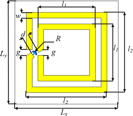
Top view of the proposed unit cell with geometric labels.
Parameter
Value (mm)
Lx
11
Ly
11
l1
5
l2
7
g
0.5
d
1
w
0.5
The bottom layer is a copper mirror. The copper was initially chosen to have a thickness of 35 µm with a metallic electric conductivity 5.8 × 10⁷ S/m. In order to attain perfect wide-band absorption, however, this simple unit cell structure was simulated under a frequency domain setup in a commercial CST (Computer Simulation Technology) microwave studio (https://www.cst.com/,0000). The above parameters were derived from the following general assumptions: that a periodic boundary condition is applied along the x and y directions. Additionally, the propagation of electromagnetic force is in the negative direction on the z axis (see Fig. 2). On the other hand, the directions of the electric field (E), and the magnetic field (H) are applied in the positive direction on the y axis and the positive direction on the x axis, respectively.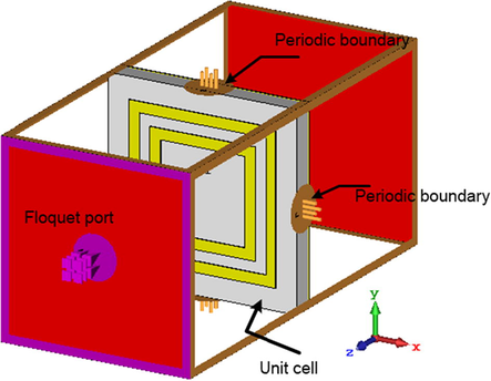
Simulation Setup.
The absorption spectrum can be found from the reflection and transmission coefficients, represented, respectively, by the scattering parameters S11, and S21, which are simulated by CST. The absorption level is therefore calculated by Eq. (1) (Landy et al., 2008; Al-Badri et al., 2017; Al-Badri and Ekmekçi, 2016).
The use of the ground plane in layer three will prevent all transmission waves, i.e. the scattering parameter S21 is zero.
3 Results
Fig. 3 shows the reflection and transmission coefficient when R = 400 ohm the magnitudes of transmission wave through the structure is 0. Therefore the absorption magnitude calculated from reflection coefficient only. Fig. 4 illustrates the simulated absorption spectra and their different resistance values. The results show that when R = 0 ohm (i.e. without lumped resistance) the proposed structure provides four absorption peaks at 79%, 99%, 88%, and 92% of a perfect absorption level at resonance frequencies 13.58 GHz, 14.82 GHz, 16.65 GHz and 18.44 GHz, respectively. Increasing R, however, results in an increase in the absorption level. The optimum R value is at 400 ohm, where absorption is at near unity level between 13.4 GHz and 16.87 GHz.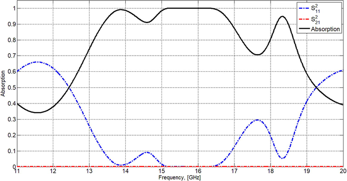
reflection, transmission coefficient and absorption spectrum.
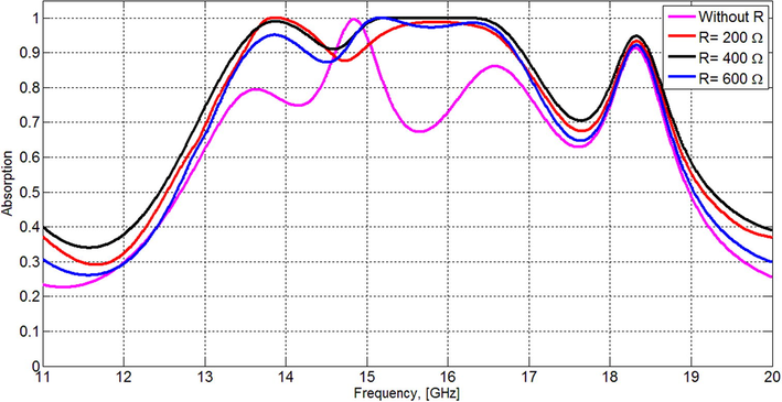
The relationship between the absorption levels spectra and changes in lumped resistance.
On the other hand, when the width of the metallic ring was changed in 0.2 mm steps, the absorption spectrum remains high but the band decreases with increasing w. Additionally, for the w = 0.5 mm, the EM is nearly fully absorbed from 13.4 GHz and 16.87 GHz (see the blue curve in Fig. 5.).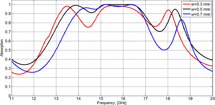
The relationship between the absorption levels spectra and the change in the width of the metallic ring (w).
The dielectric constant of the FR4 substrate was then examined with a step change 0.5 Fig. 6. It was found that as the permittivity was increased from 3.5 the absorption level increased, with a blue shift in frequency, although the band width decreased at the same time.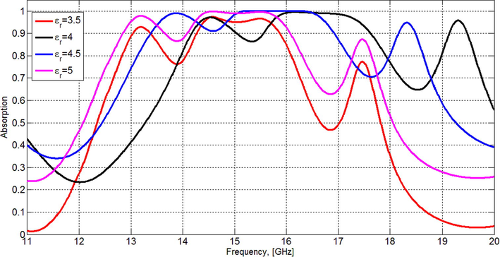
Effect on the absorption spectrum of a change in the dielectric constant.
For a better understanding of the reason behind the improvement in the absorption characteristics when the lumped resistance was increased, numerical simulations of the distribution of the electric field were conducted, using the resonance frequencies of 13.6 GHz, 14.192 GHz and 15.704 GHz, as in Fig. 7 (a, b, and c, respectively). This reveals a strong electric field distributed around the lumped resistance elements because the energy is consumed by the resistance elements (Li et al., 2016; Shi et al., 2016). This demonstrates that the lumped resistance enhances the absorption level and bandwidth, and that this outcome is a good candidate for the realization of broadband absorbers (Li et al., 2016; Shi et al., 2016).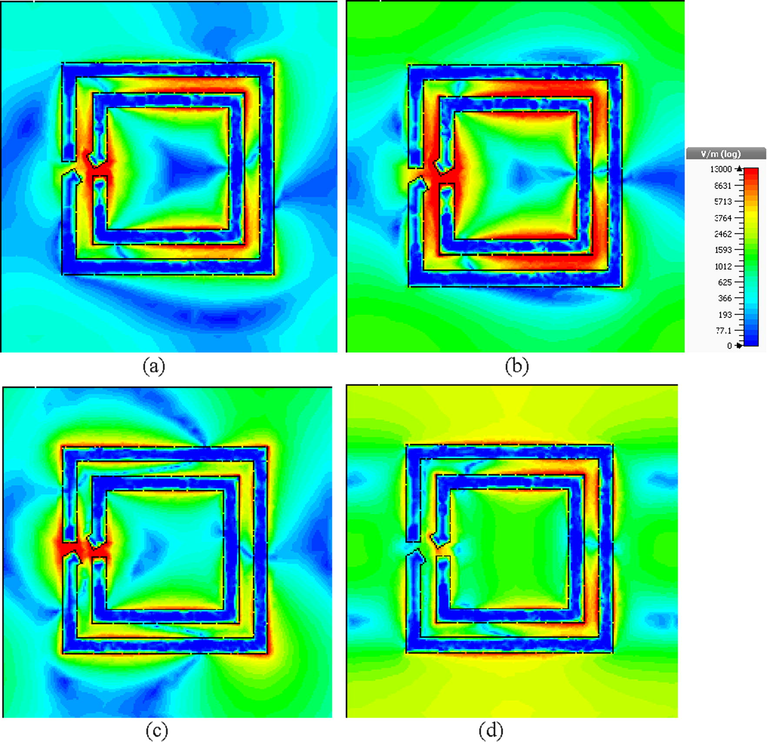
Electric field distributions (a) 13.6 GHz, (b) 14.8 GHz, (c) 16.5 GHz, and (d) 18.3.
4 Fabrication and measurement
20 × 20 unit cells were fabricated for verification of the experimental results, based on the simulated dimensions of the spiral metamaterial absorber. The proposed absorber was fabricated on one side of an FR-4 dielectric substrate using a printed circuit board (PCB) technique, with a relative dielectric constant ɛr = 4.5, tangential losses 0.04, and substrate thickness h = 2.5 mm. The measurement of the prototype was performed in a microwave anechoic chamber as suggested in (Ayop et al., 2014; Sood and Tripathi, 2016; Kollatou et al., 2013). The measurement was accomplished by using two horn antennas. A 50 separation angle was chosen between the EMW transmitter and EMW receiver. The first horn antenna connected to the port-1 of a HP-8757C VNA vector network analyser through a coaxial cable with low-loss and the second horn was connected to port-2 in order to receive the reflected wave, as shown in Fig. 8. In order prevent near field effects between the transmitter and the receiver, the distance between the two horn antennas was set at 10 cm and the angle between them at 50. In addition, the distance between the proposed absorber and horns was set at 45 cm. For the same reasons pyramidal absorbers were used between the horn antennas and around the prototype absorber to eliminate electromagnetic interference from the surrounding environment and antennas.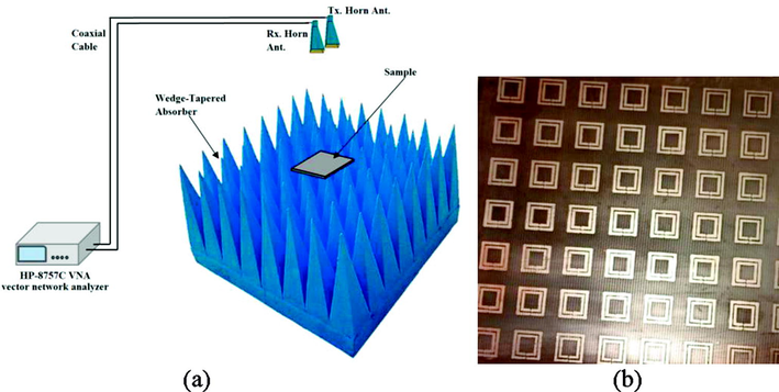
(a) Experimental set-up (b) Fabricated sample.
Fig. 9 presents a comparison between the simulated and the measured absorption spectrum results, showing that the measured results are almost the same as the simulated ones except for a slight blue shift in frequency. In measurement, the perfect absorbance band (absorption above 90%) is lower than absorption band in simulation, while the absorption band at HPBW is close to the simulated one. The lower measured band could be due to scattering from the structure and mutual coupling between both horn antennas (Ayop et al., 2014; Sood and Tripathi, 2016; Kollatou et al., 2013). The frequency shift occurs due to the resistance ohmic tolerance, prototype fabrication tolerance, calibration setup, and the dielectric dispersion of the substrate (Ayop et al., 2014; Lee et al., 2016; Bağmancı et al., 2018).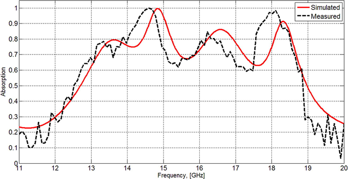
Comparison between simulated and measured absorption spectra.
The proposed absorber can therefore be said to have given good results compared with other broadband metamaterial absorbers previously reported in the literature, as summarized in Table 2. Because of use only one resistance based on one layer structure. Additionally, this structure is a good solution for power harvesting due to significantly improved absorption band width and its use of lumped resistance.
Refs.
Centre frequency (GHz)
Unit cell size (mm)
Thickness (mm)
Absorption level
Bandwidth GHz
No. of lumped resistances
No. of layers
Ghosh et al. (2014)
10.38
10
1
>90
0.68
0
1
Bhattacharyya et al. (2013)
5.15
10
1
>90
0.42
0
1
Alavikia et al. (2015)
5.55
18.5
0.79
>90
0.12
0
1
Dincer et al. (2015)
5.48
44
1.5
>90
0.23
0
1
Sood and Tripathi (2016)
11.26
4.4
1.6
>90
3.8
0
1
El Badawe and Ramahi (2018)
2.72
7
2.5
>90
0.13
1
1
Karaaslan et al. (2017)
7.5
37
4.8
>90
NA
6
3
Erkmen et al. (2018)
2.45
57.5
6.524
>90
NA
1
2
Bağmancı et al. (2018)
6.2
12
3.25
>90
4.3
8
1
Karaaslan et al. (2018)
5
160
6
>90
3.7
16
1
Shi et al. (2017)
2.27
400
0.8
>90
2.4
30
1
Proposed structure
15
11
2.5
>90
3.5 + 0.3
1
1
5 Conclusion
The wide absorption band and perfect absorption achieved in the present work demonstrates that energy harvesting based on a metamaterial with lumped resistance is a good technology to supply power to sensor networks.
References
- Complementary split ring resonator arrays for electromagnetic energy harvesting. Appl. Phys. Lett.. 2015;107(3):033902.
- [Google Scholar]
- Al-Badri, K.S.L., Ekmekçi, E., “A Numerical Study with Various Intersecting Twin Structures on Tuning the Absorption Spectra in S-Band,” URSI-TÜRKİYE’2016 VIII. Bilimsel Kongresi, 1-3 Eylül 2016, ODTÜ, Ankara.
- Monochromatic tuning of absorption strength based on angle-dependent closed-ring resonator-type metamaterial absorber. IEEE Antenn. Wireless Propag. Lett.. 2017;16:1060-1063.
- [Google Scholar]
- Triple band circular ring-shaped metamaterial absorber for x-band applications. Progr. Electromagn. Res.. 2014;39:65-75.
- [Google Scholar]
- Wideband metamaterial absorber based on CRRs with lumped elements for microwave energy harvesting. J. Microwave Power Electromag. Energy. 2018;52(1):45-59.
- [Google Scholar]
- Bandwidth-enhanced metamaterial absorber using electric field-driven Lc resonator for airborne radar applications. Microwave Opt. Technol. Lett.. 2013;55(9):2131-2137.
- [Google Scholar]
- Electromagnetic energy harvesting application based on tunable perfect metamaterial absorber. J. Electromag. Waves Appl.. 2015;29(18):2444-2453.
- [Google Scholar]
- Design and analysis of perfect metamaterial absorber in GHz and THz frequencies. J. Electromag. Waves Appl.. 2015;29(18):2492-2500.
- [Google Scholar]
- Efficient metasurface rectenna for electromagnetic wireless power transfer and energy harvesting. Progr. Electromagn. Res.. 2018;161:35-40.
- [Google Scholar]
- Scalable electromagnetic energy harvesting using frequency-selective surfaces. IEEE Trans. Microwave Theory Techniq.. 2018;66(5):2433-2441.
- [Google Scholar]
- Piezoelectric Energy Harvesting. UK: John Wiley and Sons; 2011. p. :2-3.
- Bandwidth-enhancement of an ultrathin polarization insensitive metamaterial absorber. Microwave Opt. Technol. Lett.. 2014;56(2):350-355.
- [Google Scholar]
- Polarization angle independent perfect multiband metamaterial absorber and energy harvesting application. J. Computat. Electron.. 2016;15(1):228-238.
- [Google Scholar]
- https://www.cst.com/.
- Jayarama Reddy, P., 2012. Solar Power Generation: Technology, New Concepts and Policy. CRC Press/Balkema, Leiden, The Netherlands, pp. 2–3.
- Microwave energy harvesting based on metamaterial absorbers with multi-layered square split rings for wireless communications. Opt. Commun.. 2017;392:31-38.
- [Google Scholar]
- Broad band metamaterial absorber based on wheel resonators with lumped elements for microwave energy harvesting. Opt. Quantum Electron.. 2018;50(5):225.
- [Google Scholar]
- A family of ultra-thin, polarization-insensitive, multi-band, highly absorbing metamaterial structures. Progr. Electromagn. Res.. 2013;136:579-594.
- [Google Scholar]
- Kumar, A., Singh, I.P., Sud, S.K., 2009. Indoor environment gas monitoring system based on the digital signal processor. In: Multimedia, Signal Processing and Communication Technologies, 2009. IMPACT'09. International IEEE, pp. 245–249.
- Incident angle-and polarization-insensitive metamaterial absorber using circular sectors. Sci. Reports. 2016;6:27155.
- [Google Scholar]
- Li, Y., Wang, Z., Song, Y., 2006. Wireless sensor network design for wildfire monitoring. In: Intelligent Control and Automation, 2006. WCICA 2006. The sixth world congress on Vol. 1, pp. 109–113.
- Design of a tunable low-frequency and broadband radar absorber based on active frequency selective surface. IEEE Antenn. Wireless Propagat. Lett.. 2016;15:774-777.
- [Google Scholar]
- Implementation of electromagnetically induced transparency in a metamaterial controlled with auxiliary waves. Phys. Rev. Appl.. 2015;4(2) 024013
- [Google Scholar]
- Experimental verification and simulation of negative index of refraction using Snell’s law. Phys. Rev. Lett.. 2003;90(10):107401
- [Google Scholar]
- Feasibility study of micro-wind turbines for powering wireless sensors on a cable-stayed bridge. Energies. 2012;5(9):3450-3464.
- [Google Scholar]
- Energy harvesting technologies. New York: Springer; 2009.
- Electric-field-coupled resonators for negative permittivity metamaterials. Appl. phys. Lett.. 2006;88(4):041109
- [Google Scholar]
- Experimental verification of a negative index of refraction. Science. 2001;292(5514):77-79.
- [Google Scholar]
- Broadband perfect metamaterial absorption, based on flexible material. 2016. p. :1-3.
- [Google Scholar]
- A design of ultra-broadband metamaterial absorber. Waves Rand. Complex Media. 2017;27(2):381-391.
- [Google Scholar]
- Range scaling of wirelessly powered sensor systems. In: Wirelessly Powered Sensor Networks and Computational RFID. New York: Springer; 2011. pp. 3-12
- [Google Scholar]
- Wirelessly Powered Sensor Networks and Computational RFID. Springer Science and Business Media; 2013.
- Composite medium with simultaneously negative permeability and permittivity. Phys. Rev. Lett.. 2011;84(18):4184.
- [Google Scholar]
- Development of wireless sensor network for combustible gas monitoring. Sens. Actuat. A: Phys.. 2011;171(2):398-405.
- [Google Scholar]
- Broadband ultrathin low-profile metamaterial microwave absorber. Appl. Phys. A. 2016;122(4):332.
- [Google Scholar]
- Introduction to Hydro Energy Systems: Basics, Technology and Operation. Springer Science and Business Media; 2012.
- Reliable wildfire monitoring with sparsely deployed wireless sensor networks. 2012. p. :460-466.
- [Google Scholar]
- Zhou, G., Zhu, Z., Chen, G., Hu, N., 2009. Energy-efficient chain-type wireless sensor network for gas monitoring. In: Information and Computing Science, 2009. ICIC'09. Second International Conference on Vol. 2, pp. 125–128.


