

Corrosion reduction in steam turbine blades using nano-composite coating
⁎Corresponding author. z.yaseen@kfupm.edu.sa (Zaher Mundher Yaseen)
-
Received: ,
Accepted: ,
This article was originally published by Elsevier and was migrated to Scientific Scholar after the change of Publisher.
Peer review under responsibility of King Saud University.
Abstract
The current study aims to reduce the hot corrosion issues in steam turbines for Al-Mussaib thermal power stations. To gain the aim of the study, many experimental tests were conducted by taking a sample from an existing broken steam turbine blade to identify the alloy composition and preparing samples with exact composition by powder metallurgy method, then using the electro-deposition method to coat the prepared samples by three different coating composite materials consists of TiO2 in different ratios (5, 10 and 15) g/l and 5 g/l SiO2 added to Watt's solution. To verify the efficiency of coating, several tests were conducted (surface roughness, hardness, wear, and oxidation test). The obtained results indicated that increasing the Ni-5%SiO2-TiO2 (5, 10 and 15) g/l caused an increase in the coating thickness, which is compatible with increasing the surface roughness. Also, the sample hardness increased after coating, which returned to increasing TiO2 amount (5, 10 and 15) g/l. However, wear resistance for the samples after coating by selected coating composite and 10 g/l TiO2 amount records the highest reduction in the wear of the sample.
Keywords
Hot Corrosion
Steam turbine blades
Composite coating

1 Introduction
Corrosion fatigue and stress corrosion cracking (SCC) are the two major issues with turbine parts (Zhao et al., 2021). Large amounts of corrosive contaminants in the steam that builds up in a layer on the surface of the parts throughout operational or resting periods in the wet areas of turbines are associated with these problems, which grow primarily from early corrosion pits (Dawood et al., 2020; Jonas, 1985; Radhi & Al-Khafaji, 2018). Due to the higher likelihood of steam condensation, low-pressure (LP) steam turbine bucket problems are more frequent (70%) than those of intermediate-pressure (IP) and high-pressure (HP) turbines (Mukhopadhyay et al., 1998). The HP section receives steam from the main steam lines that have been overheated. Cold reheat piping transports the steam to the reheater after passing thru HP turbine. It then needs to return to the incorporated IP and HP cylinder in the steamy reheat piping to transfer thru the IP exhaust hood. Finally, the crossover piping transports the steam to the LP turbine before exiting to the condenser through the LP exhaust. Every steam turbine contains several extraction points where steam is utilized to heat feedwater heaters (Strušnik, 2022; Vedran et al., 2022). The steam passes the saturation line throughout its expansion via the LP turbine. Corrosion degradation has typically been discovered when condensation first starts. If NaCl is introduced to the system, the salt zone is predicted NaCl amount might reach up to 28 %, which would be sufficient to corrode a steam turbine quickly (Jonas & Machemer, 2008). Because of this, the LP portion of the steam turbine suffers the highest corrosion.
Following the scientific revolution propelled by advancements in nanotechnology, the utilization of nanocomposites and hybrid materials has become integral to contemporary scientific and technological research due to their diverse range of applications (Radhi et al., 2022). These materials possess exceptional electrical and mechanical properties, exhibit optical interaction, and demonstrate high thermal conductivity with remarkable efficiency (Abed et al., 2022). The selection of an optimal method for preparing nanocomposites is a critical aspect of the field of research about these intricate materials. “Co-Deposition Techniques” refers to a method that involves using two, three, or more deposition sources. Hence, these diverse or identical sources interact synergistically and adhere to the designated samples, resulting in alloys and hybrids that exhibit exceptional properties (Jasim et al., 2023). The various types of co-deposition include electrolytic co-deposition, co-sputtering, co-evaporation, and spray co-deposition.
The electro-deposition method offers several advantages over alternative coating techniques, including hot isostatic pressing, thermal spraying, and high-velocity oxygen fuel (HVOF) (Zhang & Witman, 2018). These advantages include the ability to continuously process materials, handle complex geometries, operate under normal working pressures, rapid deposition rates, homogeneous distribution of coatings, low maintenance requirements, and decreased generation of waste (Lampke et al., 2006; Szczygieł & Kołodziej, 2005). Electro-codeposition is a highly efficient technique for fabricating Metal Matrix Composite (MMC) coatings (Camargo et al., 2016; Lelevic & Walsh, 2019). This process involves the simultaneous deposition of non-metallic and metallic particles onto pure metals or alloys. The primary objective of electro-codeposition is to enhance the resulting coatings' tribological features and resistant to corrosion (Ger, 2004). In the present context, ongoing research focuses on the co-deposition of ceramic particles, including WC, Al2O3, TiO2, Cr2O3, and SiC, in conjunction with nickel plating (Aal et al., 2007; Hu & Chan, 2006). The tribological properties primarily rely on the reinforced particles' quantity, dimensions, and arrangement (Gnjidić et al., 2001; Thiemig et al., 2007). The electroplating parameters, including stirring speed, temperature, pH, current density, and bath composition, have been observed to impact the surface morphology (Kılıç et al., 2013).
(Chen et al., 2010) used conventional electroplating Ni solution mixed with a small quantity of transparent TiO2 sol to create nanocrystalline Ni-TiO2 composite coatings. These coatings have such a slick exterior. The usual pyramidal form of the Ni nodules was replaced with a spherical shape. Additionally, the Ni particle size dramatically decreased to 50 nm. The coating matrix included well-scattered amorphous anatase TiO2 nanoparticles (approximately 10 nm). The innovative composite coating with 3.26 wt% TiO2 greatly enhanced the microhardness from 320 HV100, the conventional Ni coating, to 430 HV100. As a result, the composite coating's resistance to wear was increased by around 50%.
(Gül et al., 2012) examined the impact of particle amount on the Ni-SiC composite coatings structure made by electro-deposition. They found that Ni-SiC (MMCs) composite coatings enhanced with submicron particles on steel surfaces had good resistance to wear and high hardness, so they were utilized in applications where no wear was preferred, like tools and dies. The solutions raised the SiC particle in the electrolyte, which increased the co-deposited coatings' particle amount. The amount of coating particles decreased up to a max of 20 g/L as the SiC particle amount increased; however, this caused the metal matrix (in this case, Ni) to have its lattice distort; coating resistance to wear improved with SiC particle amount up to 20 g/L in the electrolyte; and nanocomposite Ni-SiC coatings that co-deposited increased friction coefficients and resistance to wear in comparison to films of Ni, which is related to the mixture of submicron-sized (SiC) particles in the deposited layer, strengthening the dispersion and refined grains to raise the composite coating hardness (Abed Janabi et al., 2021).
Prepared Zn-nano-TiO2 composite coatings were coated on the mild steel substrate by (Mokabber et al., 2013). Electroplating created coatings from a sulphate solution containing nanoscale TiO2 particles. The coatings' corrosion behaviour was investigated in 3–5 wt% NaCl solutions, and the microhardness was determined using the Vickers microhardness test. The variables of current density, particle content in the solution, and temp are best when compared to the composite coatings' TiO2 content. The bath was determined to have an optimal current density, particle concentration, and temp of 3 A/dm2, 5 g/L, and 40 °C. Due to the increase in the number of TiO2 particles in composite coatings enhances their hardness while having no negative impact on their ability to resist corrosion.
(Gadhari & Sahoo, 2016) explored the addition of titania particles with the micro-hardness, resistance to corrosion and wear, and friction of electroless Ni-P-TiO2 composite coatings coated on mild steel substrates at various annealing temps. The empirical findings demonstrated that when the particle concentration in the electroless solution rises, more TiO2 particles are integrated into the coatings. Hardness, resistance to wear, and resistance to coating corrosion all greatly increase in the presence of TiO2 particles. X-ray diffraction (XRD), energy dispersive X-ray analysis (EDXA), and Scan electron microscopy (SEM) analysis are used to study microstructure changes and composite coating composition.
(Antar et al., 2021) developed Ni-B-TiO2 composite coatings by including TiO2 sol in the bath solution. Several characterization tests, such as microhardness testing, progressive load scratch testing, reciprocating sliding testing, and multi-pass scratch testing, were conducted to obtain systematic research. The findings indicate that the microstructure of the Ni-B matrix was effectively altered by the TiO2 structure (crystal or amorphous). Additionally, the Ni-B deposit's excellent scratch response and improved resistance to wear were offered because of its compact structure.
Al-Mussaib thermal power station is among Iraq's electricity system's most significant power-producing facilities because of its size and closeness to the capital area. As a result, it has a substantial influence on the Iraqi economy. Most reports released from AL-Musayyib thermal power station stated that the main issue that caused the stop or rest of the steam turbine operation was the breaking or cracking of the blades. Therefore, the action that is usually taken to reduce the issues of blades is applying metal coating before the operation to increase the service life of the blades along with decreasing the hot corrosion failure. The current project aims to increase the resistant to hot corrosion of steam turbine blades for AL-Musayyib thermal power stations by applying nanocomposite coating (5 g/l SiO2 and (5, 10 and 15) g/l TiO2). Therefore, the novelty of the current research focuses on preparing samples with a similar composition to existing steam turbines experimentally by powder metallurgy method, and applying electro-deposition coating (co-deposition coating), which consists of nanomaterials (TiO2 and SiO2), to identify the changes in hot corrosion, wear resistance, and hardness before and after applying nano-composite coating (co-deposition coating) on turbine blades of AL-Musayyib thermal power stations.
2 Experimental work
2.1 Methodology
Al Mussaib thermal power station is a 1280 MW oil-fired power project. It is in Babil, Iraq, 43.28 km (26.89 mi) northwest of Hilla city center, with coordinates 32° 45′ 1″ north, 44° 16′ 51″ east. The project is presently in progress. The process occurred in several stages. Following the conclusion of the construction phase, the project was officially commissioned in the year 1987. The current proprietorship of the project is held entirely by the Ministry of Electricity in Iraq, with a full ownership stake of 100%. The power station in question operates using a steam turbine. The thermal power project is comprised of four turbines, each with a nameplate capacity of 320 MW.
The methodology of the current research consists of collecting a small sample from broken blades and conducting the XRF to identify the chemical composition of the steam turbine blades. Then, preparing samples with similar composition by powder metallurgy method, which was utilized in the other experimental tests.
2.2 X-ray fluorescent analysis
The X-Ray fluorescence test was performed on broken steam turbine blades (as shown in Fig. 1 (a and b) at the Ministry of Science and Technology. XRF tests are utilized for the chemical composition of powders and alloys. The sample analysis results have been demonstrated in Table 1, with Fe, Al and Cr as optimum ratios.
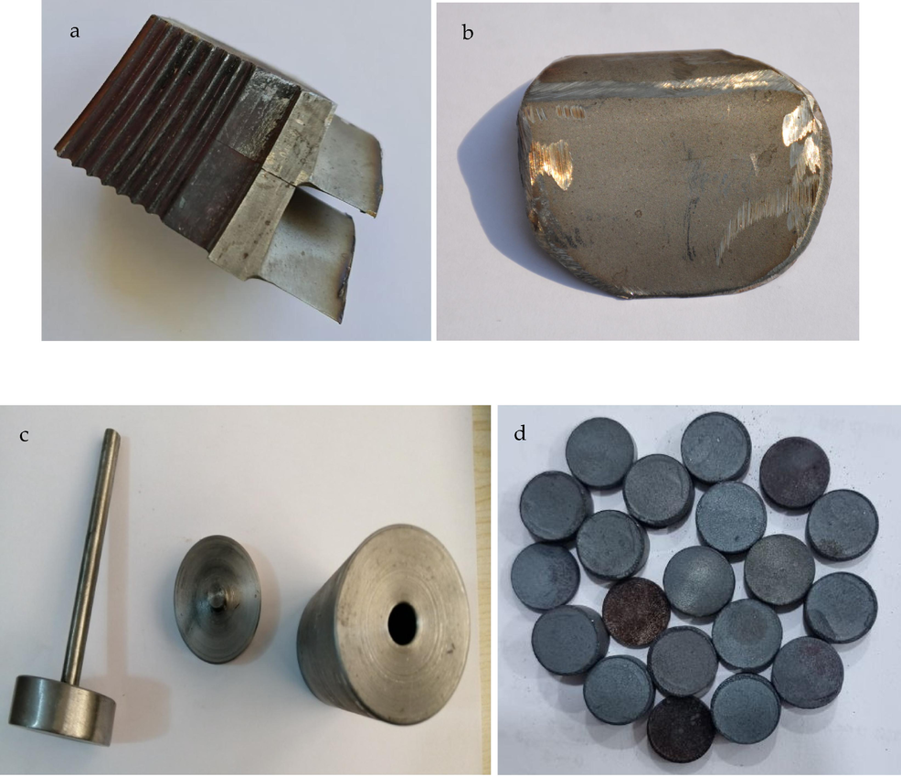
- a) broken steam turbine blades, b) xrf sample, c) the die utilized in sample preparation and d) (13 mm) diameter prepared sample.
| Elements | Value | |
|---|---|---|
| Steam Turbine Blades | Prepared samples | |
| Na | 0.5 | – |
| Mg | 0.593 | – |
| Al | 11.781 | – |
| Si | 1.642 | – |
| P | 0.041 | – |
| S | 0.268 | – |
| Cl | 0.204 | – |
| K | 0.056 | – |
| Ca | 0.270 | – |
| Ti | 0.060 | – |
| V | 0.210 | – |
| Cr | 9.997 | 7.461 |
| Fe | 73.594 | 67.961 |
| Ni | 0.220 | 9.703 |
| Cu | 0.101 | 2.835 |
| Zn | 0.043 | – |
| Mo | 0.420 | 12.039 |
2.3 Specimens preparation
2.3.1 Powder weight
After determining the percentage for each utilized material, the powder of the material was weighted by utilizing the sensitive balance type (Sartorius-BSA1245) German origin (4 deg.), located in the Laboratory of Metals in the Labs of the Department of Metallurgical Engineering - Babylon University.
2.3.2 Powders mixing
To obtain a uniform powder distribution and to obtain a good mixing of the elements, the powders have been combined utilizing the electrical rolling mixer kind (STGQM-1/5–2), located in the resistance laboratory in the Labs of the Department of Department of Metallurgical Engineering - Babylon University. Alumina balls are utilized in various sizes to confirm the powder blending, with a minimal amount of acetone added to reduce the oxidation and friction generated throughout the blending process. The mixing time is 4 h.
2.3.3 Powders compacting
This process includes compaction of the powder of each specimen by utilizing the die cylindrical one direction (made from tool steel) with a die diameter of 13 mm (4 g for each specimen), as illustrated in Fig. 1 (c and d), and by utilizing the electric hydraulic press (ct430-ct440.) which is in the resistance Lab in the Department of Metallurgical Engineering - Babylon University. The powders were pressed under a pressure of 850 MPa, and the loading rate was (0.3 N /min) for 5 min. Graphite powder with about 40 μm particle size was utilized as a lubricator to the die, and then specimens with a diameter of 13 mm and 7 mm in height were produced.
2.3.4 Sintering operation
The sintering process was conducted in the lab of thermal transactions in the Labs of the Department of Metallurgical - Babylon University by utilizing an electrical tube furnace type MTI- (GSL1600X) under a controlled atmosphere (argon gas) to inhibit the specimens oxidation.
-
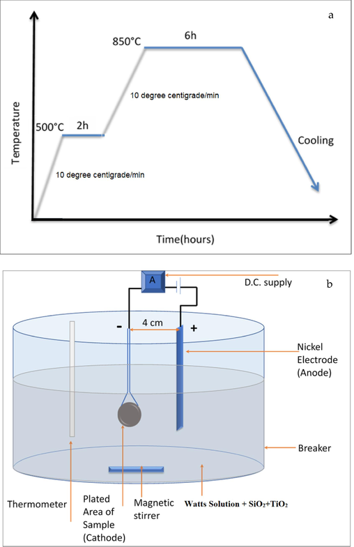
As shown in Fig. 2(a), the sintering process involves the following steps:
-
Heating from room temp(25 °C) to 500 °C
-
Stay for (2) hours at 500 °C.
-
Heating From temp 500 °C to 850 °C
-
Stay for (6) hours at 850 °C.
-
Slow cooling to room temps in the furnace with the continued presence of the Argon gas.
-
A) Heating cycle of sintering process, b) schematic of the electroplating cell.
2.4 Nickel electrode
The nickel electrode utilized is rectangular with sizes of (0.8 x4x 10) cm thickness, width, and length, respectively, with high pureness of 99.99 %. Other materials used in this work are (TiO2 with 20–30 μm Particles size supplied from Fluka chemical 89,470 company); (NiSO4·6H2O, NiCl2·6H2O, H3BO3, and SiO2 that supplied from Fluka company) and (NaOH and HCl that supplied from Sigma-Aldrich Co.LLC company).
2.5 Surface preparation for plating
Surface samples were produced as follows:
-
All surface was fully grinding utilizing (grit paper of carbide-silicon) sizes (180, 400, 600, 800), which was conducted utilizing (MP-2B grinder polisher).
-
After finishing each process, the samples were washed with distilled water and alcohol, dried utilizing an electric dryer, and then stored in a desiccator.
-
The sample’s surfaces were cleaned off by acid and alkaline solutions.
2.5.1 Alkaline cleaning
The samples were immersed in alkaline solutions material (10 wt% NaOH) for two mins at (25 °C) to eliminate any oil and dust from the metal's surface; the specimens were washed with distilled water.
2.5.2 Acid cleaning
The treatment involved the use of a hydrochloric acid (HCl) solution with a concentration of 30%. The treatment was performed at a temp of 25 °C for a duration of five seconds. The purpose of this treatment was to remove oxides. Following the treatment, the sample was rinsed with alcohol and distilled water. The samples were exposure to drying utilizing an electric dryer. Subsequently, the specimens were measured using an electric balance. Following the recording of their weights, the samples were immersed in the coating solution to initiate the electroplating procedure.
2.6 Equipment for electroplating process
The electroplating process was conducted using a beaker produced from glass with a cylindrical shape and power supply, which gave the current up to (0–6) A and the voltage to (0–20) V.
Compositions of Electroplating Bath: Many experimental works explore the feasibility of simultaneous Watts' solution and Watts' solution with various percentages of titania by adding (5, 10, 15) g\L along with 5 g\L of (SiO2). The electrolyte of watts combines boric acid, nickel chloride and nickel sulphate, as shown in Fig. 2(b).
All solutions have been generated using distilled water and subjected to chemical dissolution under acidic conditions. A total of three baths were utilized for the application of a coating onto Watts' solution, which consisted of Watts' solution combined with TiO2. Table 2 displays comprehensive data regarding the optimal performance coating that can be achieved in this research for all baths. Deposition's condition for all specimens:
-
pH = 3.5
-
Temp. = 33 °C
-
Coating duration = 30 min
-
Nickel anode = (99.9%)
-
Current density = 5.305 A/dm2
-
Voltage = 2 V
| Solution | Chemical composition |
|---|---|
| Ni –5SiO2-5TiO2 | NiSO4·6H2O = 240 g/L NiCl2·6H2O = 20 g/L H3BO3 = 20 g/L SiO2 = 5 g/L TiO2 = 5 g/L |
| Ni –5SiO2-10TiO2 | NiSO4·6H2O = 240 g/L NiCl2·6H2O = 20 g/L H3BO3 = 20 g/L SiO2 = 5 g/L TiO2 = 10 g/L |
| Ni –5SiO2-15TiO2 | NiSO4·6H2O = 240 g/L NiCl2·6H2O = 20 g/L H3BO3 = 20 g/L SiO2 = 5 g/L TiO2 = 15 g/L |
2.7 Tests
The current study undertook the examination of forthcoming assessments aimed at assessing the performance of the plating layers.
2.7.1 Coating thickness's measurements
The procedure involves the utilization of a coating thickness gauge of Type (TT 260), which possesses a device accuracy of ±0.1 µm. To obtain a representative specimen thickness, measurements were conducted at three distinct locations and subsequently averaged; the test was conducted to nickel and nickel added titania by (5, 10 and 15) g/l along with 5 g/l (SiO2) coated steel specimen.
2.7.2 Surface roughness test
The surface roughness of nickel and nickel mixed with titania by (5, 10 and 15) g/l coated low carbon steel specimen was determined utilizing the (TR-100 surface roughness tester), at Babylon University, Faculty of Material Engineering. The equipment is utilized to assess the roughness of a specimen's surface. It consists of a sensor that measures the roughness and provides a direct reading on the device's screen. The device is known for its high accuracy, with a precision of ±0.01 μm.
2.7.3 Hardness test
Vickers hardness (TH-717 Digital Vickers Hardness Tester) was determined by the hardness of nickel and nickel added titania by (5, 10 and 15) g/l along with 5 g/l of (SiO2) coated steel specimen and steel substrate without coating specimens the applied load at (200 N) and holding duration (10 s) in College of Material Engineering / Babylon University.
2.7.4 Energy dispersive X-ray spectroscopy
The Energy Dispersive X-ray model (Inspect S50 FEI company), as an analytical technique, was utilized to determine the element percentage for each layer of the coated specimen in which nickel and nickel added titania by (5, 10 and 15) g/l along with 5 g/l of (SiO2) coated steel, specimen the test was conducted in the college of pharmacy/ Babylon University.
2.7.5 Wear test
According to ASTM (G99-04), FG cylindrical specimens were produced with diameter (10) mm and length (20) mm from the prepared cylinders. These samples are grinded using emery papers: (400, 600, 800, 1000, 1200, 1500, 2000, 2500 and 3000). Specimens are backed by epoxy to produce them for testing. The wear test is conducted by utilizing (Pin-on-disc) apparatus, which has a disc of steel turning with a speed of (250) r.p.m.
-
Precise rotation's radius (r = 6) mm.
-
Figuring out the load (10) N.
-
Setting a test time limit of (0, 5, 15, 30) minutes.
The specimen is removed when the test process is complete, and its weight is determined again (W2). Executing the same steps for every test. Figuring the wear rate using the formula (Dawood et al., 2020):
W1 (g) = sample’s weighting before the test.
W2 (g) = sample’s weighting after the test.
ρ (g/mm3) = Density of material.
2.7.6 Oxidation test
Three high-temperature alloys used in heavy-duty engine applications underwent oxidation and corrosion testing. The experiments were carried out between 700 and 900-degree centigrade in conditions that included sulphur dioxide, water vapour, and salt mixes (Abi-Akar, 2000). It was discovered that the hot corrosion was strongly influenced by both the salt content and the test temp. Under the same test settings, the localized corrosion depth is substantially greater at 900 °C than at 700 °C, and salt mixes incorporating sodium sulphate seem more corrosive than those with just calcium sulphate. The specimens were submerged in motor oil and heated to 750 °C to ash the oil in a cyclical oil and ash immersion test that was devised. The specimens were then taken out of the furnace, given some time to cool, and the process was performed twice more so that ash could gather on the samples. After this, the specimens were heated for 2 days, which tested hot corrosion performance consistent with what was seen in service applications (LeBozec et al., 2008).
This test may also help with high temp alloy material selection for potential use in heavy-duty engines. The test may also be utilized to distinguish various engine lubricants and evaluate how well they work with alloys subjected to high temperatures.
3 Experimental results and discussion
Experimental findings that involved coating thickness, surface roughness, and other testing, including XRD, Hardness, and optical microscope findings, would be presented and discussed.
3.1 Energy dispersive X-ray spectroscopy
Fig. 3 demonstrates the XRD patterns for the uncoated sample. The shown patterns match the standard stainless-steel patterns available commercially.
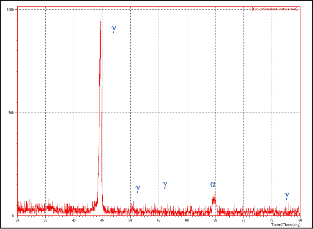
- XRD pattern ffor prepared stainless-steel sample.
3.2 Measurements of coating thickness
For coating samples, the thicknesses were increased with increasing TiO2 proportions (5, 10 and 15) g/l, as demonstrated in Fig. 4. These findings specified that the deposit rates of samples with Ni- 15TiO2- 5SiO2 are thicker than samples with Ni- 5TiO2-5SiO2, which owing to the high diffusivity of the species resulting from TiO2. Nevertheless, the thickness of the samples increased with the increasing amount of TiO2. Fig. 4 depicts the impact of the incremental proportion of titania (TiO2) in the electroplating solution of nickel. Also, the coating thickness experiences an increase as the quantity of (TiO2) incorporated in the nickel composite layer on the steel sample's surface increases.
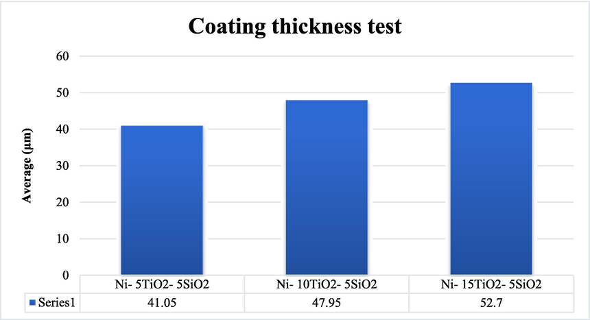
- Result of effect added titania on coating thickness test.
3.3 Surface roughness test
Fig. 5(a) demonstrates the surface roughness test findings for uncoated and coated samples coated by the composite coating. The device reading for each sample was demonstrated in Fig. 5(b, c, d). According to the provided information, it is observed that the surface exhibited a higher degree of smoothness once an amount of 5 g/l TiO2 was employed. Subsequently, the surface roughness exhibited a progressive escalation in response to the titania amount present in the coating solution, culminating in the attainment of the most pronounced roughness once the amount reached 15 g/l of TiO2. Based on the results of the coating thickness test, it can be observed that the coating thickness and surface roughness exhibit a positive correlation with the quantity of (TiO2) incorporated within the nickel composite layer applied onto the steel specimen's surface. Based on (Mazur et al., 2016), increasing the TiO2 amount led to an increase in the coating layers, which is compatible with surface roughness increasing.
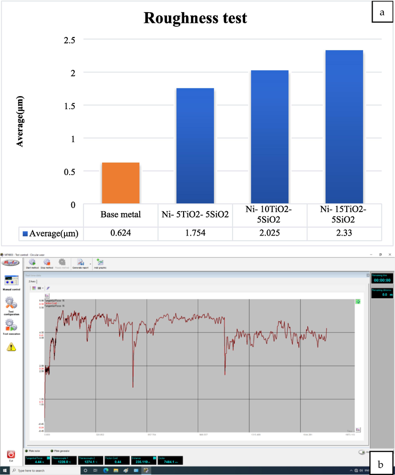
- The obtained friction coefficient from the wear device for the samples a) Surface roughness test result b) 5 g/l TiO2, c) 10 g/l TiO2, and d) 15 g/l TiO2.
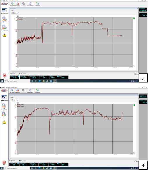
- The obtained friction coefficient from the wear device for the samples a) Surface roughness test result b) 5 g/l TiO2, c) 10 g/l TiO2, and d) 15 g/l TiO2.
The magnitude of friction experienced between two solid objects is contingent upon the specific conditions of their contact. Understanding surface microtopography is important when investigating tribological processes within the contact zone (Branko et al., 2000). The statical friction coefficient is influenced by several variables, including the mechanical characteristics of the materials involved, the roughness of the surfaces, the potential dissolution between the materials, the duration of contact, the characteristics of any lubricant film present, and the elasticity of the tribe system. Fig. 5(b, c) depicts the friction coefficient fluctuation concerning the number of sliding passes. The composite coating exhibits a notably high friction coefficient, with values of 0.44, 0.52, and 0.6. Based on (Gu et al., 2004), the relationship between friction coefficient and surface roughness is positive; increasing one leads to increasing the other.
3.4 Hardness test
The purpose of the hardness test would have been to identify how the electrodeposited TiO2 coating affected the low carbon steel's 210 HV hardness magnitudes. Additionally, research was done to determine the impact of adding ceramic titania (TiO2) particles with particle sizes ranging from 20 to 30 µm to nickel solution with additions of (5, 10 and 15) g/l on the hardness magnitudes of Ni coating and low carbon steel. The findings of the hardness test for steel samples and Ni-TiO2 layers with (5, 10 and 15) g/l TiO2 and 5 g/l SiO2. The variation in titania volume percentage in each layer causes the observed difference in hardness magnitudes between the base sample without coating and coated samples with different TiO2 ratios. The Hall-Petch correlation, which indicates that the particles size has a demonstrable impact on the material's hardness, may be used to provide a mathematical explanation (Dawood et al., 2020):
HV: Material's hardness with small particles size.
Ho: Hardness material is the multi-size grain (polycrystalline grain size).
K: Constant refers to the HV hardness slope that drawing depending on the material kind.
d: Particle's diameter.
The Hall-Petch correlation describes why ultra-fine microstructures with the same hardened material have greater hardness magnitudes of 448 HV than coarser-grained ones. After being coated with nickel hard metal, samples that were not coated became harder. Additionally, increasing the amount of TiO2 (5, 10 and 15) g/l addition increased the hardness from (210 HV) for the base sample without coating to (361 HV), (398 HV), and (448 HV). These results compatible with Rajesh et al. (Rajesh et al., 2019) findings. The Hardness tests are shown in Fig. 6.
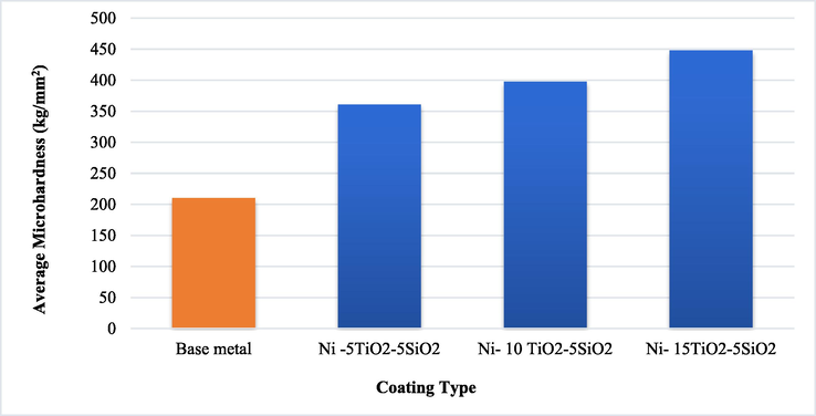
- Results of the impact of added titania on the micro-hardness test.
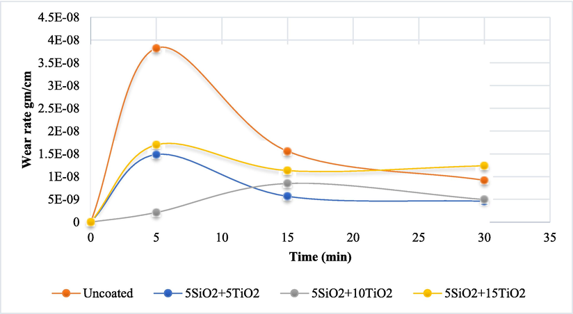
3.5 Wear test results sf
The weight of the specimen before and after the testing was obtained utilizing a sensitive balance (Denver style) with a precision of 0.1%, and the wear rate of the produced alloys was computed utilizing the gravimetric technique (0.1 g). The following formula is used to compute the wear rate:
W.R: wear rate (g/cm), ΔW: change in weight (g), Wo: Specimen weighting before testing (g), W1: Specimen weighting after testing (g), t: slip duration min (0, 5, 15, 30) min.
r: The centre radius of rotation r = 6 mm, N: speed (250 rpm).
The relationship between wear rate and slip time at 10 N applied load has been shown in Fig. 7 for coated and uncoated samples, where at 10 N, increasing the time of slip after 5 min decreased the wear rate for all selected samples. At the same time, the coated samples record a significantly improvement in wear resistance rate compared with uncoated stainless samples, and the sample coated with 5%SiO2 + 10%SiO2 could be considered the best sample compared with other coated samples.
- The findings of weight loss at 10 N lead.
The weight reduction was translated into a decrease in volume by considering each sample's density. Fig. 7 illustrates the outcomes of the wear test conducted under comparable conditions as previously described, with a load of 10 N, rotational speed of 250 rpm, and varying durations of 5, 15, and 30 min.
The present study has revealed that the deposited layer tends to crack in this spall when its thickness exceeds the optimal value of 52.7 μm. The protective nature of the layer diminishes when its thickness falls below 50 μm. Fig. 7 demonstrates that as the load increases, there is a corresponding increase in the wear rate at a constant speed, which can be attributed to the heightened sub-surface deformation caused by the strain rate. Nawal et al. (Dawood et al., 2020). have reached analogous findings concerning the sliding range, wherein it was detected that the wear rate exhibits a linear increase with greater sliding distances. Electroplated nickel coatings exhibit superior and predominantly improved properties than conventional coarse-crystalline coatings. The attributes encompass enhanced strength or micro-hardness, enhanced adhesion, heightened resistance to wear, and increased resilience against hot corrosion, an expected phenomenon wherein elevated loads result in augmented friction between the sample's surface and the rotating disc.
Furthermore, as time progressed, the decrease in volume intensified due to the increased loss of particles from the sample due to increased frictional movement. The numerical data presented herein serves to illustrate the effects resulting from the introduction of silicon oxide and titania particles into the nickel electrodeposition solution, followed by an examination of wear rates under various experimental conditions. A substantial decrease in volume loss was observed as added particles increased. The composite with the highest amount of silica (5 g/L SiO2 and 15 g/L TiO2) exhibited the lowest volume loss, suggesting that the coated layers' particles may contribute to increased hardness, leading to improved wear resistance (Dawood et al., 2020).
3.6 Oxidation test
Losing weight due to exposure to high temperature within a specific time range between (0.5 and 2) hr. At 250°, the TiO2 ratio from (0, 5 and 10) g/l reduces weight loss significantly, while increasing the amount of TiO2 to 15 g/l gives similar results as 10 g/l of TiO2, as shown in Fig. 8(a). Fig. 8(b–d) show that with increasing the heating temperature, the effect of increasing TiO2 amount from (0, 5, 10 and 15) g/l becomes clearer in reducing the loss in the samples' weight compared with uncoated samples (Gupta & Tripathi, 2011).
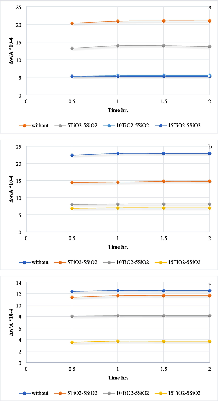
- The oxidation test results for various temps a) 250 °C, b) 300° C, c) 350° C, and d) 400° C.
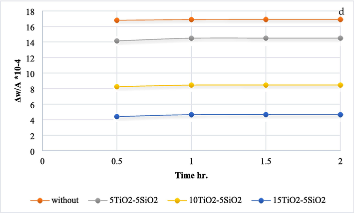
- The oxidation test results for various temps a) 250 °C, b) 300° C, c) 350° C, and d) 400° C.
(Shao et al., 2012) demonstrated that the nanocomposite coatings had a smoother and more compact surface than the pure Ni layer, a better hardness, and a lower wear rate. The anti-corrosion ability of nanocomposite coating was tested in solutions of 3.5% and 35% sodium chloride, respectively. The findings also show that the nanocomposite covering considerably increases corrosion resistance due to adding TiO2 to nickel nanocomposite coatings may enhance their mechanical features, such as wear resistance and hardness, and that the effect becomes greater as TiO2 concentration is raised. Also, after applying TiO2, (Shanaghi et al., 2009) discovered that the film uniformity was maintained in elevated temps and that there was no evidence of cracking or flaking off the substrate. Additionally, the hardness measurements explain why mild steel coated with TiO2 nanoparticles has a higher resistance to hot corrosion, with Icorr falling from 18.621 to 0.174 A/cm2.
According to Song et al. (Song et al., 2017), nanoparticles can significantly increase coated steel's hot corrosion resistance and effectively reduce agglomeration. The best-performing of the three types of nanoparticles is SiO2 nanoparticles.
4 Conclusion
Coating steam turbine blades with nanomaterials is considered one of the innovative solutions that are applied to reduce the corrosion issue in blades and improve the other steam turbine parts' properties. The current study is mainly based on using TiO2 and SiO2 as nano-coating materials, and the obtained results of experimental work can be drawn down as follows:
-
For all selected coatings, Ni-SiO2-TiO2 composite coating, the coated substrates are completely covered by a layer composite of nanoparticles in a mean particle size of 30–70 nm.
-
The composite layer (Ni-SiO2-TiO2) indicated a stable structure with outstanding crystallization and higher surface mechanical bonding due to the good incorporation of SiO2-TiO2 with the nickel matrix.
-
The composite layer (Ni- SiO2-TiO2) reduces the hot corrosion rate with uncoated at 400 °C while maximum improvement is 75% once the amount of (5SiO2-15TiO2) g/L in coated solution.
-
The findings illustrated at 10 N is the greatest wear rate in the uncoated sample, and the wear rate is reduced by 50 % for coated by Ni-SiO2-TiO2, (5SiO2-5TiO2) g/L.
-
The increment percentage of Vickers hardness is (72, 89 and 113) % for Ni- SiO2-TiO2 of 5SiO2 and (5, 10 and 15) g/L respectively of TiO2.
Acknowledgements
The authors would like to reveal their appreciation and gratitude to the respected reviewers and editors for their constructive comments. Zaher Mundher Yaseen would like to appreciate the Civil and Environmental Engineering Department, King Fahd University of Petroleum & Minerals, Saudi Arabia for their support. In addition, Zainab Al-Khafaji acknowledges the support received by Al-Mustaqbal University College (Grant number: MUC-E-0122).
Declaration of Competing Interest
The authors declare that they have no known competing financial interests or personal relationships that could have appeared to influence the work reported in this paper.
References
- Novel composite coatings containing (TiC–Al2O3) powder. Mater. Sci. Eng. A. 2007;447(1–2):87-94.
- [Google Scholar]
- Increasing of the corrosion resistance by preparing the trivalent nickel complex. Egypt. J. Chem. 2021
- [CrossRef] [Google Scholar]
- Study the effect of adding zirconia particles to nickel–phosphorus electroless coatings as product innovation on stainless steel substrate. Open Eng.. 2022;12(1):1038-1045.
- [CrossRef] [Google Scholar]
- Comparative investigation of scratch resistance and tribological performance of Ni–B–TiO2 composite coatings prepared by conventional and novel processing methods. Ceram. Int.. 2021;47(10):14438-14454.
- [Google Scholar]
- The influence of the contact surface roughness on the static friction coefficient. Tribol. Ind.. 2000;22(3&4):41.
- [Google Scholar]
- Ultrasound assisted electrodeposition of Zn and Zn-TiO2 coatings. Electrochim. Acta. 2016;198:287-295.
- [Google Scholar]
- Electrodeposition of sol-enhanced nanostructured Ni-TiO2 composite coatings. Surf. Coat. Technol.. 2010;204(15):2487-2492.
- [Google Scholar]
- Investigation corrosion and wear behavior of nickel-nano silicon carbide on stainless steel 316L. Mater. Sci. Forum. 2020;1002:33-43.
- [CrossRef] [Google Scholar]
- Effect of TiO2 particles on micro-hardness, corrosion, wear and friction of Ni–P–TiO2 composite coatings at different annealing temperatures. Surf. Rev. Lett.. 2016;23(01):1550082
- [Google Scholar]
- Electrochemical deposition of nickel/SiC composites in the presence of surfactants. Mater. Chem. Phys.. 2004;87(1):67-74.
- [Google Scholar]
- The influence of SiC particles on the compressive properties of metal matrix composites. Mater. Charact.. 2001;47(2):129-138.
- [Google Scholar]
- Preparation and characterization of hydrophobic organic–inorganic composite thin films of PMMA/SiO2/TiO2 with low friction coefficient. Appl. Surf. Sci.. 2004;221(1–4):129-135.
- [Google Scholar]
- Effect of particle concentration on the structure and tribological properties of submicron particle SiC reinforced Ni metal matrix composite (MMC) coatings produced by electrodeposition. Appl. Surf. Sci.. 2012;258(10):4260-4267.
- [Google Scholar]
- Equivalent circuit modelling of Ni–SiC electrodeposition under ramp-up and ramp-down waveforms. Mater. Chem. Phys.. 2006;99(2–3):424-430.
- [Google Scholar]
- Identify and investigation corrosion behavior of electroless composite coating on steel substrate. Open Eng. 2023
- [Google Scholar]
- Jonas, O., Machemer, L., 2008. Steam Turbine Corrosion and Deposits--Problems and Solutions. In: Proceedings of the 37th Turbomachinery Symposium.
- Effect of CTAB concentration in the electrolyte on the tribological properties of nanoparticle SiC reinforced Ni metal matrix composite (MMC) coatings produced by electrodeposition. Colloids Surf. A Physicochem. Eng. Asp.. 2013;419:53-60.
- [Google Scholar]
- Details of crystalline growth in co-deposited electroplated nickel films with hard (nano) particles. Appl. Surf. Sci.. 2006;253(5):2399-2408.
- [Google Scholar]
- Accelerated corrosion tests in the automotive industry: a comparison of the performance towards cosmetic corrosion. Mater. Corros.. 2008;59(11):889-894.
- [Google Scholar]
- Electrodeposition of NiP composite coatings: a review. Surf. Coat. Technol.. 2019;378:124803
- [Google Scholar]
- Functional photocatalytically active and scratch resistant antireflective coating based on TiO2 and SiO2. Appl. Surf. Sci.. 2016;380:165-171.
- [Google Scholar]
- Effect of electroplating parameters on properties of Zn–nano-TiO2 composite coatings. Surf. Eng.. 2013;29(1):41-45.
- [Google Scholar]
- An investigation of the failure of low pressure steam turbine blades. Eng. Fail. Anal.. 1998;5(3):181-193.
- [Google Scholar]
- Investigation biomedical corrosion of implant alloys in physiological environment. Int. J. Mech. Production Eng. Res. Dev.. 2018;8(4)
- [CrossRef] [Google Scholar]
- Preparation And Investigation A Hydroxyapatite Layer Coating On Titanium Substrate For Surgical Implants. Journal of 2022 Nanostructures
- [Google Scholar]
- Structural, optical, mechanical and dielectric properties of titanium dioxide doped PVA/PVP nanocomposite. J. Polym. Res.. 2019;26(4):1-10.
- [Google Scholar]
- Corrosion protection of mild steel by applying TiO2 nanoparticle coating via sol-gel method. Prot. Met. Phys. Chem. 2009;45(3):305-311.
- [Google Scholar]
- Mechanical and corrosion resistance properties of TiO2 nanoparticles reinforced Ni coating by electrodeposition. IOP Conf. Ser.: Mater. Sci. Eng.. 2012;40(1):12043.
- [Google Scholar]
- Effects of nanoparticles on the corrosion resistance of fluoropolymer coatings on mild steel. Surf. Eng.. 2017;33(6):451-459.
- [Google Scholar]
- Integration of machine learning to increase steam turbine condenser vacuum and efficiency through gasket resealing and higher heat extraction into the atmosphere. Int. J. Energy Res.. 2022;46(3):3189-3212.
- [Google Scholar]
- Sun, L., Berndt, C. C., Gross, K.A., 2001. Characterization and mechanical properties of flame sprayed hydroxyapatite/polymer composite coatings. In: ITSC2001, pp. 321–326.
- Composite Ni/Al2O3 coatings and their corrosion resistance. Electrochim. Acta. 2005;50(20):4188-4195.
- [Google Scholar]
- Influence of pulse plating parameters on the electrocodeposition of matrix metal nanocomposites. Electrochim. Acta. 2007;52(25):7362-7371.
- [Google Scholar]
- Exergy analysis of a complex four-cylinder steam turbine. Mach. Technol. Mater.. 2022;16(1):3-7.
- [Google Scholar]
- Zhang, Y., Witman, J.C., 2018. Electro-codeposition of MCrAlY Coatings for Advanced Gas Turbine Applications.
- Effects of tensile load hold time on the fatigue and corrosion-fatigue behavior of turbine blade materials. Int. J. Fatigue. 2021;152:106448
- [Google Scholar]


