

Translate this page into:
Analysing the design, fabrication, and performance of a compact parabolic trough collector equipped with a shell-type receiver made from a variety of metals and introduced with single slope solar still
⁎Corresponding authors. prabhu.spectra@gmail.com (A. Nagamani Prabu), Himanshu.payal@sharda.ac.in (Himanshu Payal), yusufshaikh.amu@gmail.com (Mohammad Yusuf)
-
Received: ,
Accepted: ,
This article was originally published by Elsevier and was migrated to Scientific Scholar after the change of Publisher.
Peer review under responsibility of King Saud University.
Abstract
Abstract
In this study, a unique receiver design is given for consideration. The interior of the receiver is constructed out of aluminium, while the exterior is built of copper. The water that is held within the inner copper tube is heated by a system that circulates through it, and the hollow area that is found between the two tubes is filled with vegetable oil to decrease the amount of heat that is lost. As a direct consequence of this, low-pressure steam is generated. The efficiency of the system was evaluated in comparison to the performance of another receiver made up of the same number of tubes (aluminium). The receiver that was built with tubes made of different metals had an initial efficiency of 58.61%, whereas the receiver that was built with the same type of metal had an efficiency of just 36.5%. In conjunction with this study, integrated solar still found that due to Al-Al's introduction of this still interaction, the receiver of the parabolic trough collector has a lower efficiency. The still with the parabolic trough collector has a daily average efficiency of 52.25%, whereas the still without the collector has a daily average efficiency of 36.36%.
Keywords
Compact parabolic trough collector
Shell type receiver
Single slope still
Aluminium
Copper

1 Introduction
Solar energy is free and renewable because it uses the sun's rays. The collection of solar thermal and photovoltaic (PV) energy is currently popular. Systems using evacuated tubes, flat plates, and CSPs are examples of solar thermal collectors. Concentrated solar power systems include Scheffler, linear Fresnel, solar tower, parabolic dish, compound parabolic, and parabolic trough collectors. Extensive study and development went into the parabolic trough collector, which is flexible enough to employ receivers of different materials and structures. Their research indicates that receivers play an essential role in the operation of the whole system. The receiver is heated by EMF. Use heat-absorbing, low-heat-loss materials. The transition from cold to hot receivers is troubling. Surface energy loss is reduced by insulation and coatings. The maximum temperature of a PTC tube is determined by researchers. Temperature is affected by size. PTC has submitted a large number of documents. To test the degree of receiver tube axis deflection measured from the trough's focal line, Khanna et al. (2014) created an analytical expression. The receiver tube deflects when the angle of incidence is not zero because the end facing the sun does not receive concentrated sunlight. When the rim angle is zero, the receiver tube won't block the focal line. Fuqiang et al.(2015) used Monte Carlo Ray Tracing to study how a glass cover affects heat flux inside a receiver tube. When concentrated sunlight passes through a glass cover, the heat flux magnitude and distribution are barely affected; however, an elliptical-circular cross-section reduces the heat flux gradient by 32.3%. This is correct for circular cross-sections, but heat flux is unaffected. In their review of different heat transfer augmentation methods, Sandeep and Arunachala (2016) covered evacuated receivers, nanofluids with and without inserts, and inserts with base fluids. Laminar flow benefited from PTC with insert and base fluid, while turbulence flow benefited from nanofluids with inserts. A new thin aluminium receiver was studied by Bortolato et al. (2016) for use in small linear concentrators. At 0.160 Km2w−1, they improved both the optical and thermal efficiencies, respectively, to 82% and 64%, with almost no loss in pressure. Conrado et al. (2017) recently reviewed PTC's thermal performance in depth. This included math models, simulation, and experimental setups. Their study aimed to better understand future thermal design considerations. Prahl et al. (2017) provided a comprehensive overview of receiver tube displacement and measurement techniques. Proper mirror shape and receiver tube alignment are needed to efficiently capture solar radiation. Also, they presented an airborne approach that measures the receiver tube and mirror shape. A transparent absorber tube and a gas-phase nanofluid HTF were used in the first high-temperature PTC experiment carried out by Potenza et al. (2017). The working medium was an air dispersed CuO nano-powder. A 65% success rate was achieved with temperatures maintained at 145 °C for 10 h. Xiangtao et al. (2017) created a tube absorber with pin fin arrays to enhance heat transfer. With the aid of Monte Carlo Ray Tracing and the Finite Volume Method, the flow and heat transfer capabilities of the PTC receiver were assessed. When using a receiver with pin fin arrays, the moderate Nusselt number can be raised to 9% and the overall heat transfer factor to 12%. Jamal-Abad et al. (2017) tested a metal foam-filled receiver to improve PTC performance. Copper foam with 0.9 porosity and 30 PPI pore density was inserted and tested at 0.5 to 1.5 lit/min. Using metal foam improves Nu number, increases friction, and decreases solar collector efficiency. Fraidenraich et al. (2017) derived the angular acceptance function of cylindrical parabolic collectors This technique is easy to implement, expedient, and accommodating of receiver variation. Both standard and variation receivers can benefit from this technique. Bitam et al. (2018) developed a numerical method for evaluating PTC performance by substituting a sinusoidal tube receiver for a straight tube absorber. Thermal stress and power loss are reduced by this design. Increases in the Nusselt number and friction coefficient are 45–63% and less than 40.8%, respectively.
The performance of the solar still was evaluated by Murugavel et al. (2008). using a variety of materials such as jute, cotton cloths, and natural rock. After that, Mohamed et al. (2020). looked into the asymmetrical solar still at a variety of different insulations. According to the research of Khalifa and Hamood (2009), proper insulation of a solar still could result in a productivity increase of up to 80 percent. In addition, Abu-Hijleh and Rababa'H (2003) thought about using a solar still that consisted of a sponge placed in a basin. In a passive double slope solar still containing two different quantities of base fluid water 35 kg and 80 kg. Lovedeep Sahota et al. (2016) injected Al2O3 nanoparticles into the system at varying concentrations of 0.04, 0.08, and 0.12%. It was discovered that adding 0.12% of Al2O3 nanoparticles to 35 kg of base fluid water led to a 12.2% increase in the distillate yield.
El Gharbi et al. (2011) did a numerical comparison of the Fresnel lens and the parabolic trough revealing that the latter is more efficient. The total amount of energy input into the still had an effect on the solar still's basin water temperature, evaporation rate, and freshwater production to some extent. The efficiency of a modified double-slope solar still combined with a parabolic trough concentrator was investigated by Sanjay and Sinha (1996). Lawrence and Tiwari (1990), Tiris et al. (1998). and Tiwari et al. (2016). Evaluated enhanced solar still-solar collector systems due to their higher water productivity compared to traditional solar stills. Tiris et al. (1998) and Tiwari et al. (2016). Tiwari et al. (1998), Lawrence et al. (1990), and Tiris et al. (1998). Sharif et al. (2013) calculated the maximum hourly productivity of solar energy still connected to flat collectors and heat pipes to be 0.875 L per square meter per hour. Singh et al. (2020) investigated the performance of a double-slope solar still with two flat plate collectors in their study.
This research aims to develop a new shell-type linear receiver with tubes made of both similar and dissimilar metals using plant extracts of vegetable oil sandwiched among aluminium and copper (aluminium on the outside) (Al-Al). To predict the performance of the proposed system, experiments were carried out with both an Al-Al and an Al-Cu receiver. Furthermore, to look into how Al-Al receivers can improve their performance with solar stills.
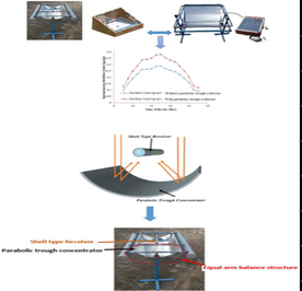
2 Focusing device, parabolic trough type, small
Using a foam sheet and a PVC pipe that is just 0.002 m thick, we can create a compact parabolic trough solar collector that measures 0.9 m by 0.6 m. Acrylic sheeting was used to give the trough the necessary support while it was being bent into the shape of a parabola. In order to redirect solar energy into the receiver tube, a highly reflective silver sheet has adhered to the trough's curved surface. See Fig. 1 for a photo of the proposed system's 0.45 m2 aperture. In this case, the focal length of the parabolic trough is calculated to be 0.13 m. During the day, the trough's tracking mechanism, which is based on equal arm balance, follows the sun's path to maximize productivity.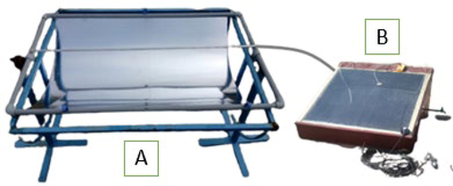
(A) shows a photograph of a linear compact parabolic trough collector with receiver. Fig (A) and (B) Parabolic trough Integrated solar still.
2.1 Receptor of the shell variety
A new take on the shell-type linear receiver is constructed from two hollow cylindrical tubes, one made of Al and Cu and the other of Al and Al, with vegetable oil inserted amongst the tubes. Both the Al-Cu and Al-Al tube receivers are depicted in Fig. 2a and 2b, respectively, in the image shown below. With taping and threading for installation on the focal plane of the parabolic trough collector, as shown in 2c, the receiver tubes can be attached to the supporting structure (see Fig. 3).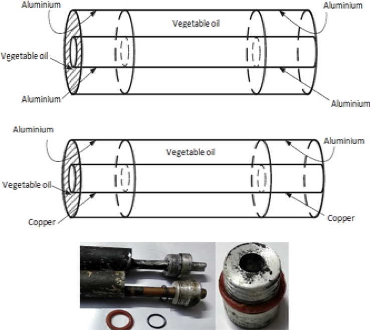
Diagrammatic and photograph representation of an aluminium – aluminium and copper receiver tube.
Schematic and photograph of the shell type Receive.
2.2 Design of single slope wick-type solar still
Fig. 1(B) shows a wick-type single-slope solar still. One square metre can evaporate. 4 mm of condensing glass protects the still's top. Inner and outer still enclosures are 1 by 1 by 0.38 m and 1.05 by 1.05 by 0.38 m, respectively. Glass wool, a good thermal insulator with 0.0038 W/mK, was used between the inner and outer enclosures. The still lost less heat to the atmosphere. The water reservoir is 13 degrees from the still's evaporation area, where the still holds water. Jute wicking is black painted. Consistent coating and unclogged wick capillaries are priorities. The remaining wick is draped over the still's slanted side and partially submerged in the reservoir.
Equation is pertaining to the proposed linear parabolic trough collector has been utilized with the reference to the results obtained by Dereje et al. (2012) and as follows
Concentration ratio is given below:
Frame angle is given as,
Aperture width
Aperture area and linear Receiver area which is defined as
Focal line has been calculated from the Eq. (3) as
Depth of the parabola is given below:
Arc length of parabolic curved surface is
Latus rectum = width of the parabola ( ) when the rim angle is 90°
Surface area of the concentrator is
Diameter of rounded receiver
Compact parabolic trough Collector's efficiency and heat gain obtained through fluid has been calculated using the equation.
Instantaneous efficacy of the system
Thermal efficiency of the system
S1 - aluminium surface specific heat capacity.
Surface specific heat capacity of aluminium (S1).
Specific heat capacity of a thermomic fluid, denoted by the symbol S2,
The specific heat of water is denoted by the symbol S3.
Specific heat capacity of copper surfaces, denoted by the letter S.
M1 = surface mass in a similar metal on the exterior.
Metallurgical Fluid Mass M2.
Mass in M3 of similar metal lining the inside.
M4 = water density.
Water mass (M4).
Contrasting metal surface mass, or M6.
Mass M7 of similar metal on the inside surface.
The initial and final surface temperatures are denoted by TSei and TSef, respectively.
Temperatures of the thermomic fluid at the start and end of the experiment.
Surface temperatures measured at the beginning and end of the interior.
Water temperature at start and finish (TSwi,TSwf).
The exterior surface's TDSei and TDSef temperatures are the initial and final temperatures, respectively.
Both the initial and final temperatures of the thermodynamic fluid are denoted by the symbols TDSti and TDStf.
Initial and final interior surface temperatures, denoted by the notation (TDSii, TDSif).
Comparing the difference between the water's temperature at the start and finish (TDSwiTDSwf).
3 Strategies for conducting experiments
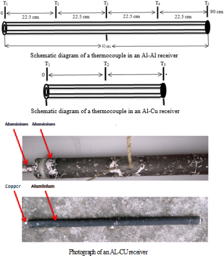
The parabolic trough system had a 0.13-meter focal length and 0.45-meter aperture. Experiments were conducted in Karpagam University's Physics Laboratory in Coimbatore. At predetermined intervals, a calibrated K-type thermocouple was inserted into the receiver tube to measure heat transfer fluid temperature. After calibration, a single K-type thermocouple measured fluid inlet and outlet temperatures. At 9 a.m., we began taking digital thermometer and solar radiation monitor readings every half hour. A typical day in November 2016 involved testing Aluminum-Aluminum and Aluminum-Copper receiver tubes. Both tubes were made of aluminium. A gate valve maintained 0.00125 kg/s of heat transfer fluid through the receiver tube. This value was calculated using the optimal heat transfer fluid flow through the receiver tube. Fig. 4a shows the Al-Al receiver, while Fig. 4b shows the Al-Cu thermocouple receiver. Fig. 4c and d show the system's two receiver tubes. Installing tubes on the focal plane (see Table 1).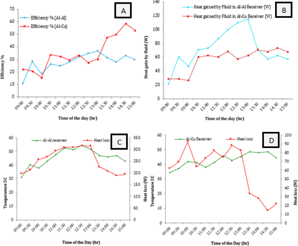
(A). How AL-AL and AL-CU receivers' lightning-fast performance varies over time (B) Throughout the day, heat gain varies (C)Temperature swings and heat loss over the course of the day for an Al-Al receiver (D) Daytime fluctuations in heat loss and temperature measured from an Al-Cu receiver.
Parameter
Al-Cu
Al-Al
Rim angle
90
90′
Focal length(F)
13
13
Aperture width (Wa)
0.52 m
0.52 m
Diameter of the receiver tube(Do)
0.028 m
0.028 m
Length of the trough and receiver (L)
0.40 m
0.9 m
Aperture area
0.22
0.45
Concentration ratio (C)
6.26
5.69
Reflectivity of the collector(y)
0.7
0.7
Tracker
Semi-automatic
Semi-automatic
4 Findings and analysis
4.1 Changes in AL-AL receiver temperature over time
The proposed system has been evaluated using a linear Al-Al receiver, and the temperature of the heat transfer fluid is monitored continuously throughout the day at predetermined time intervals. A calculation was made to determine the average temperature of the receiver after readings were taken at intervals of 0.225 m from the inlet. In addition, the temperatures of the heat transfer fluid's inlet and outlet were measured, and the difference in temperature between the two was computed to determine the effectiveness of the system. Table 2 shows the fluctuating inlet and outlet temperatures, as well as the average temperature of the receiver and the temperature differential that exists between the inlet and outlet temperatures, over the course of time. This graph demonstrates that the average temperature of the receiver gradually climbs throughout the day, eventually reaching a peak of 54.3 degrees Celsius around lunchtime. The highest temperature that was ever recorded for the heat transfer fluid outlet was 52 degrees Celsius at thirteen o'clock in the afternoon, while the highest temperature that was ever recorded for the heat transfer fluid inlet was only 27 degrees Celsius. Because of the random nature of the intensity of solar radiation, the temperature at the outlet will increase as the amount of solar radiation increases. Table 2 shows the temperature of the receiver as determined by readings taken at intervals of 0.225 m from the inlet. Because the initial temperature of the heat transfer fluid is lower than that of subsequent temperatures, the variability of the receiver temperature at position one (T1) is always lower than that of subsequent temperatures. The temperatures inside the receiver tube are relatively stable until thirteen o'clock, when they start to fall as the day draws to a close and night approaches.
Al-Al Receiver
Time Duration
09:00
09:30
10:00
10:30
11:00
11:30
12:00
12:30
13:00
13:30
14:00
14:30
15:00
Inlet Temperature ° C
26
26.5
27
26.5
28
28.5
28.9
29
30
30.5
31
30
29
Receiver Temperature ° C
31
40.4
37.9
42.8
47.7
52.4
51.2
54.3
51.6
47
46
46
42.8
Out let Temperature ° C
30
38
36
40
42
45
48
50
52
44
42
42
40
Temperature Difference ° C
4
11.5
9
13.5
14
16.5
19.1
21
22
13.5
11
12
11
Postion T1 ° C
30
32
31.5
40
40
40
36
40
35
35
42
42
40
Postion T2° C
31.5
42
40
44
50
52
50
52
50
48
46
46
44
Postion T3° C
32
46
42
48
52.5
61
58
57.5
61
52
48
50
46
Postion T4 ° C
31.5
42
40
42
50
56
56
60
58
50
44
48
42
Postion T5° C
30
40
36
40
46
53
56
62
54
50
50
48
42
Al-Cu Receiver
Inlet Temperature ° C
26
26.5
27
26.5
28
28.5
28.9
29
30
30.5
31
30
29
Receiver Temperature° C
34.5
37.1
42
41.3
38
41.3
46
42.6
45.3
48.6
48
48.6
44.6
Out let Temperature° C
31.5
32
32
38
40
40
42
40
42
44
44
44
42
Temperature Difference ° C
5.5
5.5
5
11.5
12
11.5
13.1
11
12
13.5
13
14
13
Postion T1° C
31.5
38
42
42
38
42
42
44
48
52
50
52
48
Postion T2° C
42
42
46
44
40
44
48
44
48
50
50
50
44
Postion T3° C
30
31.5
38
38
36
38
48
40
40
44
44
44
42
4.2 Changes in Al-Cu receiver temperature over time
Table 2 shows a temperature versus time plot is created using the average temperature of an Al-Cu receiver, the inlet and outlet temperatures of the heat transfer fluid, and the temperature difference between the inlet and outlet temperatures. The average temperature of the receiver tube reached its highest point at 13:30, when it was 52 degrees Celsius, according to the data collected. The heat transfer fluid in the system reaches its maximum temperature of 44 degrees Celsius at 13:30, when the average receiver temperature is at its highest, making it the system's hottest point overall. The temperature difference between the heat transfer fluid's inlet and outlet temperatures is always greater for an Al-Cu receiver than for an Al-Al receiver. This is due to the inner copper tube's high specific heat capacity and good thermal conductivity. Furthermore, as the temperature of the outer aluminium tube rises above that of the inner copper tube, the convection of heat energy through the vegetable oil to the outer tube decreases. Table 2 shows the results of temperature measurements taken every 0.22 m from the receiver tube's inlet. It was discovered that the temperature of the receiver tube and the amount of solar input have a complex relationship.
4.3 Al-Al and Al-Cu receiver efficiency varies over time
The instantaneous effectiveness of an Al-Al and Al-Cu receiver is shown in Fig. 4(A). The Aluminium-copper receiver performs best during regular working hours. Convective heat transfer is decreased by copper's higher specific heat capacity. Vegetable oil is placed in the space between the copper and aluminium tubes to lessen convection. Al-Al has a 37% instantaneous efficiency, compared to 59% for Al-Cu. Both varieties of receiver tubes have a higher thermal efficiency in the morning. Because the trough aperture always receives the same amount of radiation, this holds true throughout all operational phases.
4.4 Change in temperature over time for Al-Al and Al-Cu receivers
The proposed system with linear Al-Al and linear Al-Cu receiver tubes shows a gradual increase in heat gain up to 13:00 h before levelling off. This trend is depicted in Fig. 4(B). The heat gain from the Al-Cu receiver tube follows the same pattern, peaking around noon but dropping off after that. The Al-Al receiver tube generates more heat than the Linear Al-Cu receiver due to its larger aperture area and longer length. Shorter and with a narrower aperture than its Al-Al counterpart, the Al-Cu receiver tube is nonetheless a significant improvement over its predecessor. Due to less heat transfer between the tubes, the linear Al-Cu receiver tube outperforms its linear Al-Al counterpart.
4.5 Both Al-Al and Al-Cu receivers experience a gradual but continuous increase in heat loss and temperature over time
The receiver tube's heat index and energy loss (in Al-Al and Al-Cu, respectively) during operation are depicted in Fig. 4(C) and (D), respectively. Fig. 4(C) shows that the rate of heat loss through an Al-Al tube is proportional to the strength of the sun's rays up until about 13:00, after which it begins to decline. When the fluid motion between the inner and outer tubes becomes saturated at 13:00 hrs, it is because both tubes are made of Al-Al.
As can be seen in Fig. 5(D), the Al-Cu receiver tube's heat loss does not follow the pattern of the sun's irradiance; instead, it reaches its maximum around 13:30 and then slowly declines throughout the afternoon to evening. This is because convection between Cu and Al tubes is not the same because the two metals have different specific heat capacities and different ways of moving heat.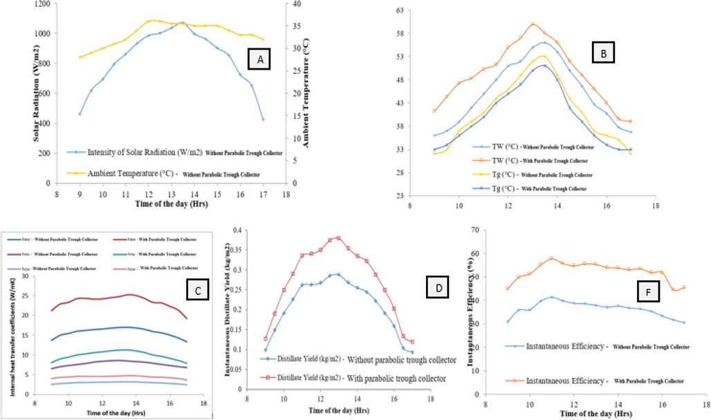
(A) Ambient temperature and intensity of solar radiation for the experimental days (B) Water and condensing glass cover temperature (C) convective, radiative and evaporative heat transfer coefficients (D) Instantaneous distillate yield (E) Instantaneous efficiency of the still.
4.6 Al-Al and Al-Cu receivers experience time-dependent changes in heat loss and solar radiation
Table 3 shows how linear Al-Al and linear Al-Cu receivers perform in terms of heat loss and solar radiation. Over the course of a day, heat loss in Al-Al receiver tubes is greater than that in linear Al-Cu tubes. When it comes to heat absorption, the linear Al-Cu receiver tube outperforms its competitors. When using a copper tube as the heat transfer fluid flow conduit, heat loss can be reduced by filling the space between the inner and outer copper tubes with vegetable oil. Furthermore, by increasing the aperture area of the linear Al-Cu receiver tube, the capacity to absorb solar radiation can be increased. This applies regardless of where the tube is in relation to the troughs. The proposed system employs the equal weight balance tracking method, which has been demonstrated to successfully track the motion of the sun by Nagamani Prabu et al. (2016).
Heat Loss
Time Duration
09:00
09:30
10:00
10:30
11:00
11:30
12:00
12:30
13:00
13:30
14:00
14:30
15:00
Radiation
626
674
815
852
936
978
982
1002
998
715
658
600
615
AL-Al
04:33
07:26
17:24
09:07
20:09
01:40
07:55
15:07
08:52
05:24
06:28
00:00
17:24
AL-Cu
62.4081
69.39
92.53
63.96
73.581
82.30
74.53
88.4
82.60
33.56
27.87
14.21
21.61
Thermic Fluid Temperature (vegetable oil)
Al-Al
32
42
40
42
44.5
49
53
55
57.5
44
41
43
40
Al-Al
36
36.5
38
38
40
44
48
46
48
46
44
48
44
Table 3 shows time-dependent temperature changes in the annulus between two tubes in the linear Al-Al and linear Al-Cu receivers. Vegetable oil is used as a heat transfer medium in this case. Because convection is prevented in the linear Al-Cu case, the thermic fluid in the Al-Cu receiver tube is kept at a lower temperature than the thermic fluid in the linear Al-Al receiver tube. Thermic fluid used to fill the space between the tubes reduces the ease with which heat can transfer from the copper tube to the aluminium tube even further. This is because thermic fluid makes it much more difficult for heat to move through it due to how poorly it allows heat to move by convection.
4.7 Solar still system integrated parabolic trough collector with Al-Al receiver
Solar radiation and ambient temperature were measured using a solar radiation monitor and a digital thermometer. The proposed still was tested in April in Coimbatore's climate using a parabolic trough collector. For the still, a circular trough outperformed a parabolic trough. Fig. 5(A) depicts typical experimental days with and without a parabolic trough, as well as solar radiation and ambient temperature. The graph shows that the sunny days in April 2021 had the same ambient temperature and solar radiation. Solar radiation reached 1072, 1065, and 1075 W/m2 at 13.5 h, and the air temperature was 36 degrees Celsius.
The experiment's equipment was set up at 8:00 a.m., and the first readings were taken at 9:00 a.m. Salty water from the reservoir travels up the submerged slanted wick and is absorbed by the jute wick. Solar radiation aids in wick evaporation by pushing vapour toward the glass cover. The glass cover's underside condensed water vapour, which dripped into the still's collection channel. The amount of distilled water in the collection channel was measured every 30 min. Regularly taken measurements. Using a calibrated Copper-Constantan thermocouple, we took multiple readings of the saline water temperature at the wick surface (Tw) and the condensing glass cover surface temperature (Tg).
Parabolic trough collector of proposed still tested with and without other parts. Convective, radiative, and evaporative heat transfer coefficients were calculated for the still with and without an integrated parabolic trough collector. This was Dunkle's intent. Fig. 5(B) shows still water and condensing glass cover temperatures with and without a parabolic trough collector. The graph shows that the single slope wick-type solar still without the Parabolic tough collector has a lower reservoir water temperature. Parabolic tough collectors absorb more sunlight. The jute wick's capillary action heated and thinned the salt water. Dunkle's expression, which uses the water and cover temperatures to determine heat transfer, has been used to determine the internal heat transfer coefficients as follows.
Convective heat transfer coefficient from water to condensing glass cover surface
Radiative heat transfer coefficient from water to condensing glass cover surface
Evaporative heat transfer coefficient from water to condensing glass cover surface
The internal heat transfer coefficients of the still with and without a parabolic trough collector in the water tank are shown in Fig. 5(C). The graph clearly shows that the radiative, convective, and evaporative heat transfer coefficients for the still-integrated parabolic are significantly higher than those obtained for the parabolic trough collector that is still missing. The presence of surface plasmons in a parabolic trough still improves the evaporative heat transfer coefficient by lowering the viscosity of the water and allowing it to flow continuously across the surface of the wick. The convective and radiative heat transfer coefficients for the parabolic trough collector, which is still in use, have been improved. The addition of a parabolic trough to a still increases the rate at which heat is transferred within the still. Fig. 5(D) depicts the instantaneous distillate yield of the still with and without PTC integration. The temperature gradient between the evaporating and condensing surfaces of the glass cover influences the distillate yield. The temperatures of the evaporating and condensing surfaces of the still-integrated parabolic trough collector were found to be significantly different. This occurs as a result of a heat exchange between the salty solar radiation and the salty water within the parabolic trough collector. As a result, the ocean becomes warmer. The preheater, which absorbs solar energy, rapidly heats the salt water. The distillation process is unaffected, but the result is increased evaporation. The graph clearly shows that the still integrated parabolic trough increased output while requiring little extra effort.
The expression for instantaneous distillate yield is used to calculate instantaneous efficiency.
5 Conclusion
The shell-shaped receiver, which is formed of various metals and contains a layer of vegetable oil in the centre, greatly improves the system's performance. In the suggested arrangement, the Al-Cu receiver tube increased the temperature of the heat transfer fluid at the exit while decreasing the quantity of heat lost through convection. The flow rate of the heat transfer fluid can be adjusted to produce low-pressure steam. An Al-Cu tube has the largest heat gain since it has the lowest heat loss. Throughout the day, Al-Cu receiver tubes demonstrate steady system efficiency. The system is proportional to the strength of the sun's rays and changes in the same basic way that solar power does. The system is efficient, produces no toxic by-products, and can deliver a large amount of thermal energy for a variety of uses at a reasonable cost. The daily average efficiency of the still with and without the parabolic trough collector is 52.25% and 36.36%, respectively. When compared to the still without nanoparticles, the still with a parabolic trough collector produced a higher distillate yield. Over a 24-hour cycle, the still with the parabolic trough collector produced a larger distillate yield than the still without the parabolic trough collector.
Acknowledgement
The authors extend their sincere appreciation to the Researchers Supporting Project number (RSPD2023R682), King Saud University, Riyadh, Saudi Arabia for the support.
Declaration of Competing Interest
The authors declare that they have no known competing financial interests or personal relationships that could have appeared to influence the work reported in this paper.
References
- Experimental study of a solar still with sponge cubes in basin. Energy Convers. Manage.. 2003;44(9):1411-1418.
- [Google Scholar]
- Single axis solar tracker for parabolic trough cylindrical concentrator, international journal of innovative research in science. Eng. Technol.. 2016;5(9):15953-15962.
- [Google Scholar]
- Numerical investigation of a novel sinusoidal tube receiver for parabolic trough technology. Appl. Energy. 2018;218(February):494-510.
- [Google Scholar]
- Experimental study of a parabolic trough solar collector with fl at bar-and-plate absorber during direct steam generation. Energy. 2016;116:1039-1050.
- [Google Scholar]
- Thermal performance of parabolic trough solar collectors. Renew. Sustain. Energy Rev.. 2017;67:1345-1359.
- [Google Scholar]
- Design support system for parabolic trough solar collector. J. Appl. Sci.. 2012;12(23):2474-2478.
- [Google Scholar]
- A new approach for obtaining angular acceptance function of non-perfect parabolic concentrating collectors. Sol. Energy. 2017;147:455-462.
- [Google Scholar]
- Effects of glass cover on heat flux distribution for tube receiver with parabolic trough collector system. Energy Convers. Manage.. 2015;90:47-52.
- [Google Scholar]
- Experimental investigation on a solar parabolic trough collector for absorber tube filled with porous media. Renew. Energy 2017
- [Google Scholar]
- Effect of insulation thickness on the productivity of basin type solar stills: an experimental verification under local climate. Energy Convers. Manage.. 2009;50:2457-2461.
- [Google Scholar]
- Performance correlations for basin type solar stills. Desalination. 2009;249(1):24-28.
- [Google Scholar]
- Effect of angle of incidence of sun rays on the bending of absorber tube of solar parabolic trough concentrator. Energy Procedia. 2014;48:123-129.
- [Google Scholar]
- Theoretical evaluation of solar distillation under natural circulation with heat exchanger. Energy Convers. Manage.. 1990;30(3):205-213.
- [Google Scholar]
- An experimental study on single basin double slope simulation solar still with thin layer of water in the basin. Desalination. 2008;220:687-693.
- [Google Scholar]
- Experimental investigation of transparent parabolic trough collector based on gas-phase nanofluid. Appl. Energy. 2017;203:560-570.
- [Google Scholar]
- Absorber tube displacement in parabolic trough collectors – A review and presentation of an airborne measurement approach. Sol. Energy. 2017;157:692-706.
- [Google Scholar]
- Solar parabolic trough collectors : A review on heat transfer augmentation techniques. Renew. Sustain. Energy Rev. (August 2015):1-14.
- [Google Scholar]
- Transient model and comparative study of concentrator coupled regenerative solar still in forced circulation mode. Energy Convers. Manage.. 1996;37(5):629-636.
- [Google Scholar]
- Experimental studies on a solar still coupled with a flat plate collector and a single basin still. Energy Convers. Manage.. 1998;39(8):853-856.
- [Google Scholar]
- Heat transfer enhancement analysis of tube receiver for parabolic trough solar collector with pin fin arrays inserting. Sol. Energy. 2017;144:185-202.
- [Google Scholar]
Further reading
- Experimental and theoretical study of a solar desalination system located in Cairo, Egypt. Desalination. 2007;217:52-64.
- [Google Scholar]
- Experimental study of a solar still with sponge cubes in basin. Energy Convers. Manage.. 2003;44:1411-1418.
- [Google Scholar]
- A novel integrated solar desalination system with a pulsating heat pipe. Desalination. 2013;31(1):206-210.
- [Google Scholar]
- Experimental study of productivity progress for a solar still integrated with parabolic trough collectors with a phase change material in the receiver evacuated tubes and in the still. J. Energy Storage. 2020;32:102007
- [Google Scholar]
- Experimental and financial investigation of asymmetrical solar stills with different insulation. Appl. Energy. 1995;52:265-271.
- [Google Scholar]
- A comparative study between parabolic trough collector and linear Fresnel reflector technologies. Energy Proc.. 2011;6:565-572.
- [Google Scholar]
- Thermo-physical characteristics of passive double slope solar still loaded with MWCNTs and Al2O3-water based nanofluid. Mater. Today: Proc 2020
- [Google Scholar]
- Effect of Al2O3 nanoparticles on the performance of passive double slope solar still. Sol. Energy. 2016;130:260-272.
- [Google Scholar]
- Parametric study of an active and passive solar distillation system: energy and exergy analysis. Desalination. 2009;242:1-18.
- [Google Scholar]


