Translate this page into:
Plane failure in rock slopes – A review on stability analysis techniques
⁎Corresponding author. tkraghuvanshi@gmail.com (Tarun Kumar Raghuvanshi) tarunraghuvanshi@yahoo.com (Tarun Kumar Raghuvanshi)
-
Received: ,
Accepted: ,
This article was originally published by Elsevier and was migrated to Scientific Scholar after the change of Publisher.
Peer review under responsibility of King Saud University.
Abstract
In stratified sedimentary and meta-sedimentary rock formations ‘plane mode’ of rock failure is very common. The plane failure occurs when a structural discontinuity plane such as; bedding plane, fault plane or preferred orientations of a joint set dips or daylight towards the valley or excavation at an angle smaller than the slope angle and greater than the angle of friction of the discontinuity surface. The stability of the slope, having plane mode of failure, depends on the geometry, rock type, potential failure plane characteristics, groundwater conditions, dynamic loading and the surcharge conditions. The slope may demonstrate these conditions in a simple uniform manner or there may be complex conditions owing to variability in the slope geometry and heterogeneity in the slope material. The stability of the slope, having plane mode of failure, can be assessed by different methods which can be broadly classified as conventional and numerical methods. Conventional methods include; kinematic methods, empirical methods, limit equilibrium and probabilistic methods, whereas numerical methods include continuum, discontinuum and hybrid methods. Each of these methods has their own advantage and limitations owing to the slope conditions, application requirement and capability of an expert. In this paper a comprehensive review on governing parameters and various stability analysis techniques for plane mode of failure in rock slopes is presented.
Keywords
Rock slope stability
Plane failure
Limit equilibrium
Numerical methods
1 Introduction
In rock slopes plane, wedge, toppling and rock fall are common modes of failures (Tang et al., 2016; Lee and Wang, 2011; Yoon et al., 2002; Hoek and Bray, 1981; Hocking, 1976). Plane mode of failure generally occurs in slope formed by stratified sedimentary and meta-sedimentary rock formations. The plane failure in rock slope occur when a structural discontinuity plane dips or daylight towards the valley at an angle smaller than the slope face angle and greater than the angle of friction of the discontinuity surface (Fig. 1) (Tang et al., 2016; Kovari and Fritz, 1984). The strike of the potential discontinuity surface must be nearly parallel to the slope face (Fig. 1) and there must be release surfaces present on either sides of the sliding mass which provides least resistance during the event of sliding (Fig. 2). In addition, a tension crack must also be present in the upper portion of the slope (Fig. 1). Under such conditions the rock mass, which rests on the discontinuity plane, will slide down the slope when shearing stresses becomes more than the resisting forces (Bell, 2007; Hoek and Bray, 1981; Hocking, 1976). In this paper a comprehensive review on plane failure mode in rock slopes is presented. The review includes discussion on governing factors and the techniques available for the plane failure analysis.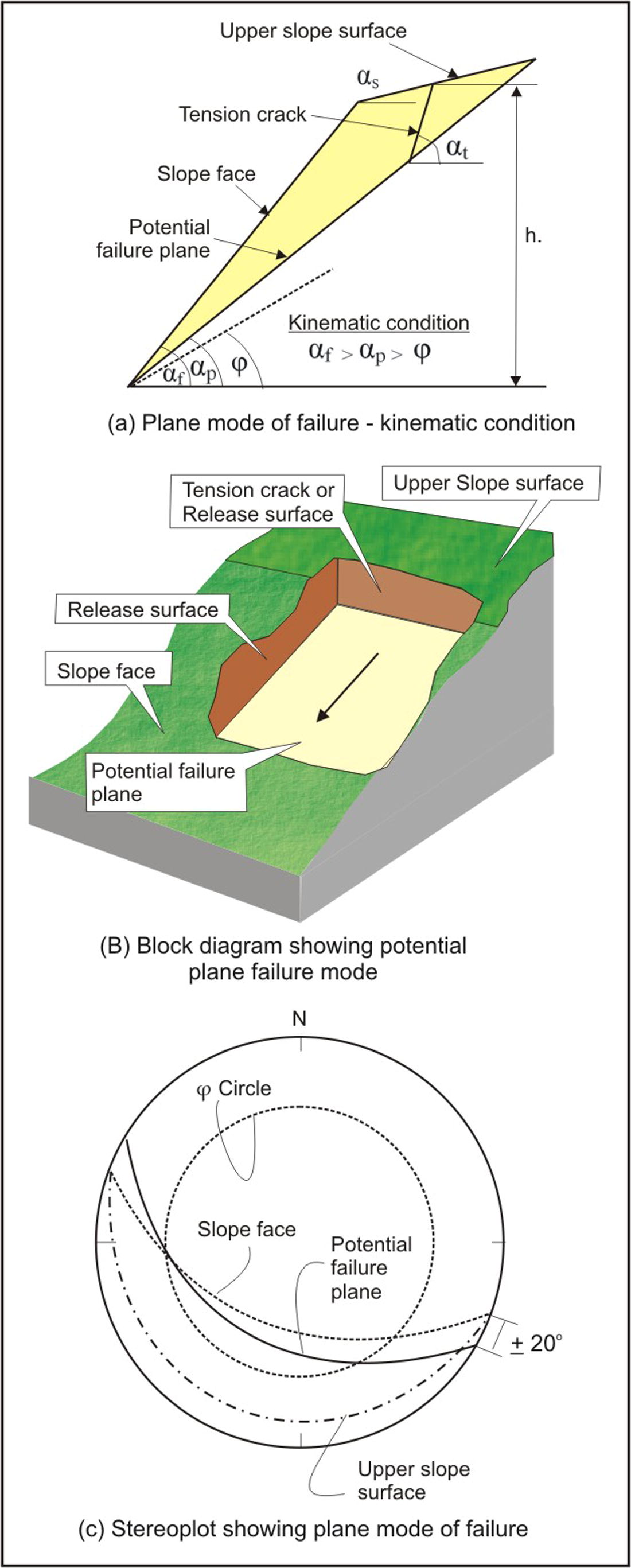
Potential plane mode of failure.
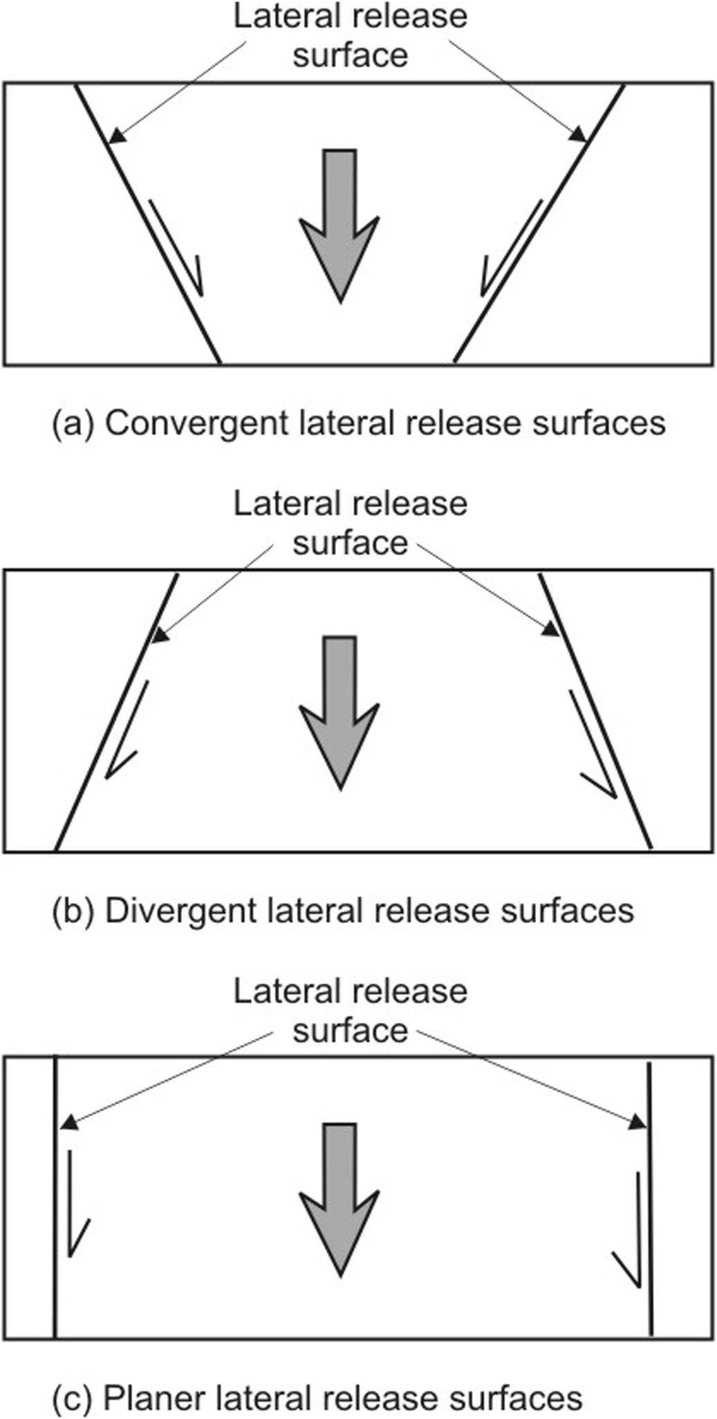
Orientation of lateral release surfaces.
2 Governing factors
Stability of the slope is concerned with the relationship between driving and resisting forces. Some factors contribute for driving forces whereas others add to the resisting forces. Therefore, these governing factors are very important for the stability analysis of the rock slopes in general and for plane mode of failure in particular. The main internal governing factors are; geometry of the slope, potential failure plane characteristics, surface drainage and groundwater condition (Wang and Niu, 2009; Ayalew et al., 2004; Turrini and Visintainer, 1998; Anbalagan, 1992), whereas the external factors are rainfall, seismicity and manmade activities (Girma et al., 2015; Raghuvanshi et al., 2014; Wang and Niu, 2009; Dahal et al., 2006; Gorsevski et al., 2006; Malamud et al., 2004; Bommer and Rodrı’guez, 2002; Keefer, 2000). These factors in combination will be responsible in defining the stability condition of the slope.
2.1 Internal factors
2.1.1 Geometry of the slope
The geometry of the slope having plane mode of failure is defined by; inclination of the slope (αf), upper slope surface inclination (αs), slope height (h), potential failure plane – dip amount (αp) and dip direction (Ψp), tension crack or upper release joint (αt) and the lateral release surfaces (Hoek and Bray, 1981) (Fig. 1). The main driving force acting on the slope is the gravitational force which is directly proportional to the slope inclination (αf). Steeper slope will be more susceptible for instability (Hamza and Raghuvanshi, 2017; Raghuvanshi et al., 2014). As the upper slope inclination (αs) increases, additional rock mass will add to the weight component, thus shearing stresses will increase and instability in the slope will be induced (Sharma et al., 1995). Increase in height (h) of the slope will increase the shear stresses (Raghuvanshi et al., 2014; Anbalagan, 1992; Hack, 2002). Further, if potential failure plane (αp) daylight on the slope face at an angle smaller to the slope face angle (αf) and greater than the angle of friction (φ) the kinematic condition is satisfied and failure can take place (Sharma et al., 1995; Kovari and Fritz, 1984; Hoek and Bray, 1981) (Fig. 1). When the shear stress exceeds the shear strength along the potential failure surface, tension crack (αt) develops in the upper portion of the slope. The rock mass will tend to detach along this tension crack (Sharma et al., 1995; Hoek and Bray, 1981) or release joint (Sharma et al., 1999) (Fig. 1). On the either side of the potential sliding mass there must exists lateral release surfaces which provides least resistance to the sliding mass. These release surfaces can be convergent, divergent or planer (Sharma et al., 1995; Hoek and Bray, 1981; Price, 2009) (Fig. 2).
2.1.2 Potential failure plane characteristics
The main resisting stress along the potential failure surface is defined by the shear strength parameters namely; cohesion (c) and the angle of friction (φ) (Fig. 3). The shear strength along the potential failure plane depends on the engineering geological characteristics of the discontinuity surface. These include orientation of the failure plane, continuity of the failure surface, roughness of the surface, aperture etc. (Johnson and Degraff, 1991). Assessment of these characteristics is important in defining the shear strength of the potential failure plane. The angle of friction (φ) along the potential failure plane can be estimated by law of friction proposed by Barton and Bandis (1990). The commonly used methods for estimation of ‘φ’ and ‘c’ are empirical methods and back analysis. The empirical methods are based on rock mass classification systems (Bieniawski, 1989; Hoek et al., 2002). Further, back analysis is considered to be the most reliable method to make an estimate for cohesion (c) along the potential failure plane for the anticipated conditions (Sharma et al., 1999; Singh and Goel, 2002).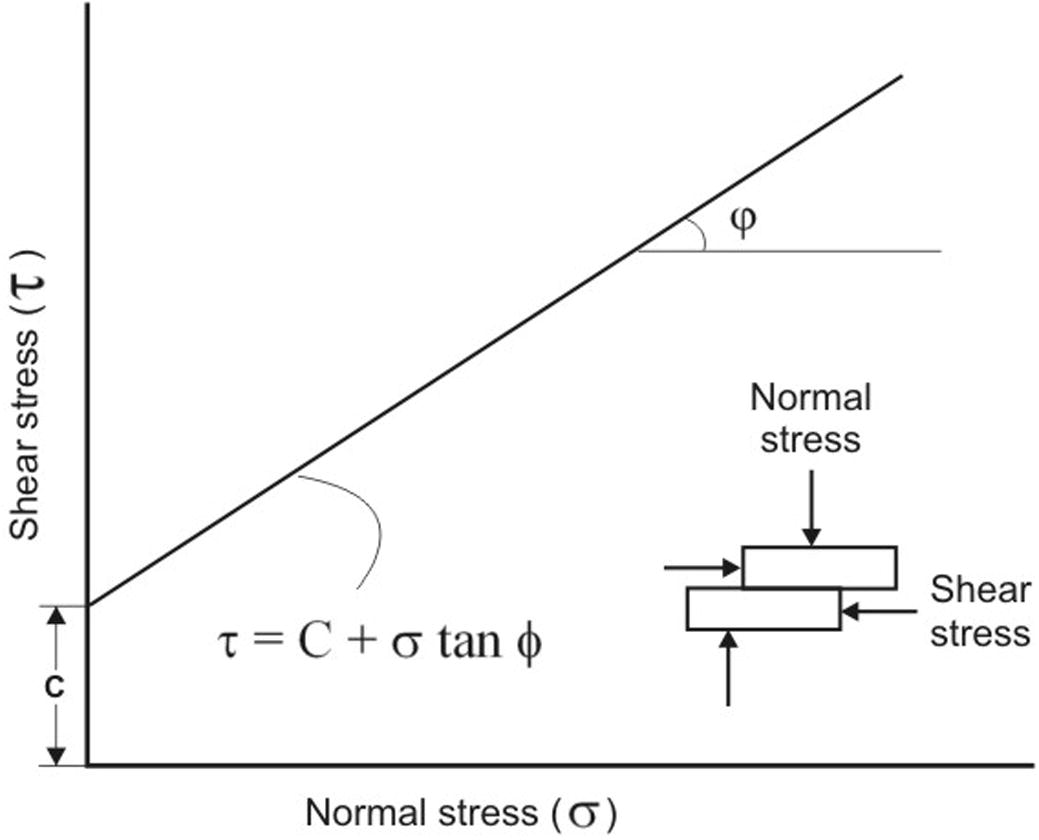
Relation between normal and shear stress along potential failure plane.
2.1.3 Surface drainage and groundwater conditions
Surface flow on upper slope will easily find its way through the tension crack to recharge the potential failure surface. Thus, this water in tension crack will develop a water force (V) and an uplift water force (U) along the potential failure surface, this will reduce the stability of the slope (Hossain, 2011; Ahmadi and Eslami, 2011; Sharma et al., 1995; Hoek and Bray, 1981) (Fig. 4). The water along the potential failure surface will reduce the shear strength and also lubricate the surface that may facilitate the sliding process (Raghuvanshi et al., 2015; Hack, 2002). Therefore, it is very important to consider surface drainage conditions while assessing the stability of the slope.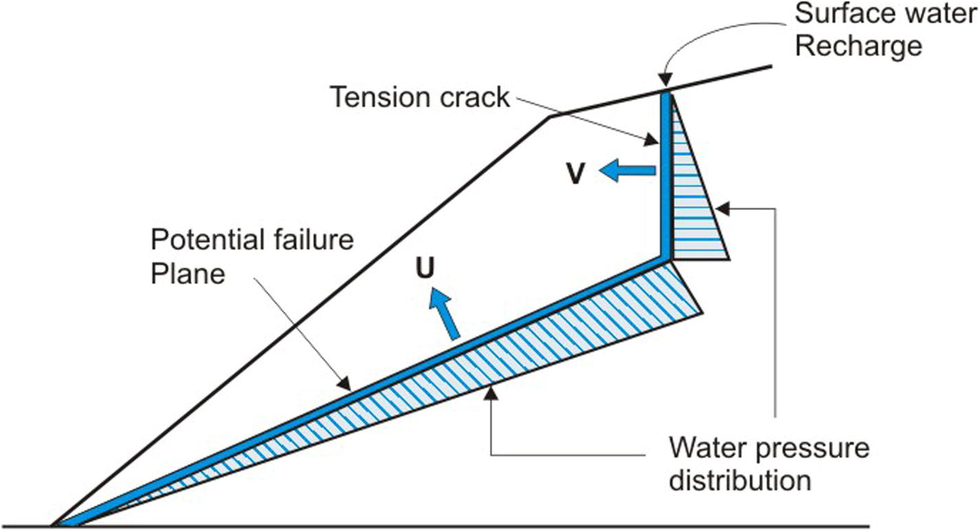
Water force and pressure distribution in slope having potential plane mode of failure.
2.2 External factors
2.2.1 Rainfall
Rainfall is a principal instability triggering factor in rock slopes (Ermias et al., 2017; Raghuvanshi et al., 2014; Dahal et al., 2006; Ayalew et al., 2004; Dai and Lee, 2001; Collison et al., 2000). This is evident from the fact that most of the slopes fail during rainy season (Ermias et al., 2017; Raghuvanshi et al., 2015, 2014). Surface flow on upper slope due to rainfall will easily find its way through tension crack to recharge the potential failure surface. Thus, instability in the slope will be induced.
2.2.2 Seismicity
The rock slopes under seismic loading are subjected to accelerations which induce instability in the rock slope (Ermias et al., 2017; Bommer and Rodrı’guez, 2002; Keefer, 2000). The slopes which are stable under static conditions may destabilize under dynamic seismic loading (Hoek and Bray, 1981). Under seismic loading the slope having potential plane mode of failure may easily destabilize, as one of the resolved component of the horizontal acceleration acting along the potential failure plane will add to the driving forces and the other component will be acting against the resisting forces (Fig. 5).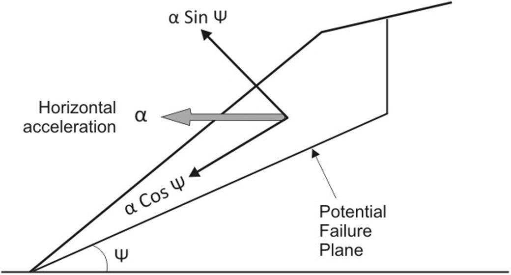
Slope subjected to horizontal acceleration during seismic loading.
2.2.3 Manmade activities
Road construction is the major manmade activity on the hill slopes (Ermias et al., 2017; Wang and Niu, 2009). Very often slopes are cut in unplanned manner, leaving unsupported overhanging steep slopes. The natural slope stability is disturbed and instability in slope is induced (Tang et al., 2016). If kinematic conditions for plane mode of failure exist, the slope may easily fail. Other aspect related to manmade activities on slopes is, adding surcharge to the slope by constructing buildings and other civil engineering structures on the slopes. Such surcharge will directly add to the weight of the siding mass and if kinematic conditions exists probability for slope failure will increase (Shukla et al., 2009).
3 Stability analysis techniques
Stability analysis for a slope, having plane mode of failure, can be carried out by adopting various techniques. Broadly, these techniques can be classified into; (i) conventional approach; that includes kinematic methods, empirical methods, limit equilibrium methods (Karaman et al., 2013; Baba et al., 2012) and probability methods whereas, (ii) numerical methods; includes continuum modeling, discontinuum modeling and hybrid modeling (Stead et al., 2006; Eberhardt, 2003).
3.1 Conventional approach
3.1.1 Kinematic method
Kinematic methods are based on the principle of kinematics which deals with the geometric condition that is required for the movement of the rock block over the discontinuity plane, without considering any forces responsible for the sliding (ZainAlabideen and Helal, 2016; Karaman et al., 2013; Kulatilake et al., 2011; Goodman, 1989). The commonly used kinematic method to determine possible mode of failure was initially proposed by Markland (1972) and later it was redefined by Hocking (1976). For kinematic check stereographic projections are used (ZainAlabideen and Helal, 2016). On a stereo-net the representative great circles for all preferred discontinuity planes, present on the given slope, are plotted. Also, great circle for slope face and friction circle, corresponding to the friction angle of the discontinuity plane, are plotted. The zone demarcated by the friction circle and the slope face is designated as sliding envelope (Fig. 6). If any great circle of a discontinuity plane, having strike nearly parallel to the slope face, falls within this sliding envelope, kinematic condition is satisfied (Ali et al., 2015).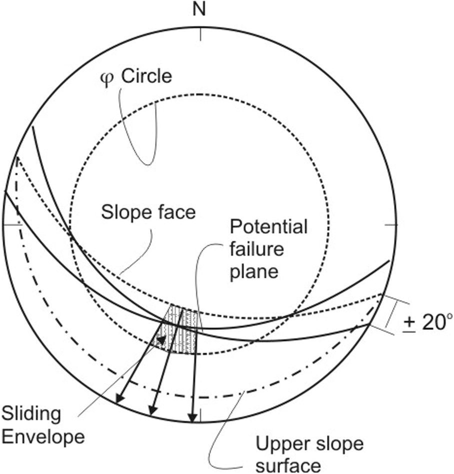
Kinematic condition for plane mode of failure.
Hoek and Bray (1981) further redefined the kinematic condition for plane mode of failure by introducing two more general conditions; (i) the strike difference between the slope face and the potential failure surface must be nearly parallel (±20°) and (ii) there must be lateral release surfaces on either sides of the sliding block which must not provide any resistance to the sliding. Price (2009) classified these lateral boundaries as convergent, divergent and planar (Fig. 2). Further, Yoon et al. (2002) divided lateral release surfaces into two types; (i) when discontinuity intersect the potential failure plane and (ii) when free faces intersects the slope face. The lateral release surfaces may lead to single faced slope (SFS) sliding or multi faced slope (MFS) sliding. Slopes which are MFS show varied sliding conditions owing to complex slope geometric characteristics. Yoon et al. (2002) suggested kinematic check for such multi faced slopes. Further, Lisle (2004) presented equations to calculate daylight envelope for plane failure in rock slopes. Kinematic check is the first step to proceed for other analytical techniques.
3.1.2 Empirical methods
In past several empirical methods based on rock mass classification systems have been developed. The important slope classification systems are; classification proposed by Selby (1980), Slope Mass Rating (SMR) (Romana, 1985), Modified Slope Mass Rating (MSMR) (Anbalagan et al., 1992), Slope Stability Probability Classification (SSPC) (Hack, 1998) and rock mass classification system for slopes proposed by Liu and Chen (2007).
SMR classification, proposed by Romana (1985) can be used to assess the stability condition of a rock slope (Alzo’ubi, 2016). SMR utilizes Bieniawski’s (1979) rock mass rating (RMR), the relationship between parallelism of slope and discontinuities, dip amount of the discontinuity and relation between the slope inclination and dip of the discontinuity. Also, mode of excavation is considered in SMR. Anbalagan et al. (1992) modified SMR by considering wedge mode of failure as a separate case. For stability analysis of slope, having plane mode of failure, both SMR and MSMR classifications can be utilized. Hack (1998) proposed SSPC to classify the rock mass and to define its in situ stability condition with probability of failure to occur. The SSCP accounts for discontinuity relations with the slope, degree of weathering and the shear strength of the slope material (Singh and Goel, 2002). In SSPC the exposed rock mass is characterized to represent in its imaginary un-weathered and undisturbed state for which suitable corrections for weathering and excavation disturbance are made (Karaman et al., 2013; Hack, 1998). Further, Liu and Chen (2007) proposed a classification system for the assessment of rock slope stability. In this classification geological, geometric and environmental factors were considered. By combining Fuzzy Delphi method and Analytic Hierarchy Process a model to estimate the rock mass quality was developed.
3.1.3 Limit equilibrium methods
Limit equilibrium methods are relatively simple in its application, as compared to the numerical methods (Tang et al., 2016; Yang and Zou, 2006; Eberhardt et al., 2004). For plane mode of failure analysis, the limit equilibrium methods were proposed by many researchers, such as; Tang et al. (2016), Ahmadi and Eslami (2011), Shukla et al. (2009), Price (2009), Hoek (2007), Zheng et al. (2005), Sharma et al. (1999), Ling and Cheng (1997), Sharma et al. (1995), Hoek and Bray (1981) etc. In limit equilibrium method various forces responsible for driving of the rock mass and the resisting forces are evaluated and the ratio of resisting forces to driving forces at equilibrium, defines the factor of safety (FOS) (Price, 2009; Sharma et al., 1995; Hoek and Bray, 1981). If FOS value is more than ‘1’ it suggest stable slope, if less than ‘1’ unstable and if FOS is equal to ‘1’ the slope is in a critical state of equilibrium (Hossain, 2011). The FOS will be affected by various governing factors such as; geometry of the slope, failure plane characteristics, water forces and external triggering factors. The FOS is inversely proportional to the height of the slope. Increase in height (h) of the slope will increase the shear stresses, thus FOS will decrease (Raghuvanshi et al., 2014; Anbalagan, 1992; Hoek and Bray, 1981; Hack, 2002; Raghuvanshi and Solomon, 2005). Steeper slope angle will directly affect the FOS. The main driving force acting on the slope is the gravitational force which is directly proportional to the slope inclination (Hamza and Raghuvanshi, 2017; Raghuvanshi et al., 2014). Similarly, increase in upper slope inclination will increase FOS (Sharma et al., 1995). Also, the FOS is directly proportional to the shear strength of the potential failure plane (Hoek and Bray, 1981). The shear strength of the potential failure plane is defined by parameters; cohesion (c) and angle of friction (φ). As the shear strength increases, FOS will increase.
Hoek and Bray (1981) provided a 2D analytical solution for plane mode of failure. For this method the required general conditions are; (i) the dip of the potential failure plane should be less than the slope inclination (ii) the dip of the potential failure plane must be greater than the angle of friction, (iii) the strike of the potential failure plane must be nearly parallel (±20°) to the slope and (iv) there must be lateral boundaries on either side of the sliding block which place negligible resistance to the sliding mass. Besides, few assumptions were also made by Hoek and Bray (1981). The geometry of the slope used in this analytical solution is presented in Fig. 7. In Hoek and Bray (1981) technique it was assumed that tension crack is vertical and the upper slope is horizontal. Later, Sharma et al. (1995) explained that upper slope is seldom horizontal for natural slopes and in most of the cases it is inclined. They also showed that the value of FOS decreases considerably when the upper slope surface angle is increased. Similarly, the tension crack may not always be vertical. Thus, Sharma et al. (1995) modified the Hoek and Bray’s (1981) analytical solution by considering the actual upper slope inclination and non vertical tension crack (Fig. 7). Further, Ling and Cheng (1997) proposed an analytical method for the slope stability assessment. The rock mass was assumed to be a rigid body having plain strain condition. For this analytical formulation, forces due to the weight of the sliding mass, water forces and the seismic coefficients were considered. Later, Sharma et al. (1999) proposed analytical solution for plane mode of failure in which they redefined the tension crack as a release-joint which may be a pre-existing discontinuity. Shukla et al. (2009) also presented an analytical solution for the plane failure analysis by considering factors such as; the weight of the sliding mass, water forces in the tension crack and along the potential failure plane, shear strength parameters of the potential failure plane, slope inclination, surcharge load and the seismic factors. Further, Ahmadi and Eslami (2011) proposed an analytical solution in which the effect of water forces was studied.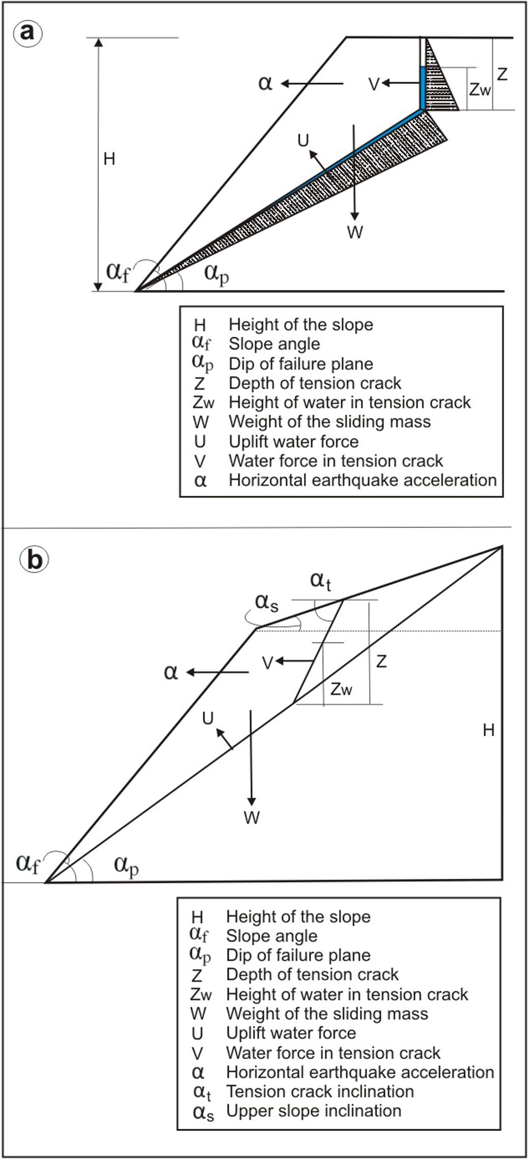
Geometry of slope and various force vectors used in (a) Hoek and Bray (1981) analytical technique (b) Sharma et al. (1995) modified technique.
3.1.4 Probabilistic methods
The probabilistic methods facilitate to incorporate parameters, which show uncertainty, in a systematic way and define the stability condition of the slope in probabilistic terms (Alzo’ubi, 2016; Chowdhury, 2010). For probabilistic analysis of a slope, having plane mode of failure, the parameters to be used are first defined as fixed dimension parameters and as random variables (Hoek, 2007). Fixed dimension parameters are mainly the geometric parameters which can be obtained directly from the geometry of the slope such as; slope height, slope inclination, upper slope inclination and dip of the potential failure plane. The random variables are those which show uncertainty in their values and may vary considerably such as; cohesion (c) and angle of friction (φ), ratio of depth of water in tension crack to the depth of the tension crack etc. (Hoek, 2007). FOS is the ratio between the resisting forces and the driving forces. As earlier stated, since some of the parameters used in resisting and driving forces are random variables therefore, such parameters will have probability distribution over certain range, rather than a fixed absolute value. Thus, the probabilistic analysis will also provide FOS as random variables with probability distribution (Chowdhury, 2010).
In probabilistic framework for plane failure analysis, three methods are followed (i) First Order Second Moment approach (FOSA), (ii) Point estimate approach (PEA) and (iii) Monte Carlo Simulation approach (MSA). The FOSA provide expected value of FOS and its variance. In PEA method the discrete values of FOS can be estimated at the mean values of the variables (Chowdhury, 2010). Through PEA, mean and standard deviation of FOS can be computed when input parameters show random behavior (Hoek, 2007). In MSA method from the probability distribution of each variable, discrete values are randomly selected. Later, FOS is evaluated by utilizing a set of different discrete values of various parameters. Multiple simulations are made by repeating the process by taking different set of the discrete values of various variables (Zhao et al., 2016; Chowdhury, 2010).
3.2 Numerical methods
The rock slopes in general, demonstrates variability in its geometry, heterogeneity in geological formation, non-linearity in the potential failure plane, uneven distribution of the water forces in the slope with induced surcharge and the seismic loading conditions (Alzo’ubi, 2016). Stability condition of such complex slopes cannot be evaluated by following conventional techniques (Karaman et al., 2013; Eberhardt, 2003). In order to simulate such complexities, numerical methods are required. In general, numerical methods; include continuum, discontinuum and hybrid methods (Tang et al., 2016; Stead et al., 2006; Eberhardt, 2003).
3.2.1 Continuum modeling
The continuum modeling approach can be applied to those rock slopes where the rock mass is relatively uniform such as; heavily disintegrated rock mass which can be considered as continuous all over the slope. The variability of various governing parameters can be simulated in the stability analysis for the static and dynamic conditions. The continuum modeling is based on finite element, finite difference and boundary element methods. The basic input data that is required for continuum modeling approach are; constitutive model, in-situ stress, shear strength parameters for surfaces, groundwater etc. For the slope stability analysis through continuum modeling finite difference and finite element models are commonly used. These methods can suitably be applied for weak rock masses in which failure results due to intact rock deformation or through the discrete stratified discontinuities (Stead et al., 2006). The major limitation with continuum techniques is in defining rock mass as continuum, for which simplifications are needed. Thus, the final results are highly influenced by such simplifications (Hack, 2002).
3.2.2 Discontinuum modeling
The discontinuum modeling is suitable for discontinuous rock mass which contains discontinuities and the failure mechanism is controlled by pre-existing discontinuities. In discontinuum analysis movement of intact rock blocks bounded within discontinuities and the deformation of intact rock can be addressed for both, static and the dynamic conditions (Stead et al., 2006). The input data required for modeling includes data on slope geometry, discontinuity characteristic, discontinuity shear strength and stiffness, in-situ stress and groundwater data. For discontinuum modeling, distinct element method and discontinuous deformation analysis are widely used. For plane failure mechanism distinct element method can be used (Stead et al., 2006). The discontinuum method is quite effective to simulate the discontinuity behavior and to assess the rock slope stability for given conditions.
3.2.3 Hybrid modeling
Hybrid modeling approaches utilizes the combined capabilities of both continuum and discontinuum methods. The strength of the rock mass is a combined effect of strength along the rock joints and the strength of the intact rock between the joints (Alzo’ubi, 2016). Complex slope and discontinuity geometry can be considered in hybrid modeling approach. Step-path geometries can be simulated by hybrid finite-discrete element method with fracture propagation approach (Stead et al., 2006).
4 Effectiveness of stability analysis techniques
Each of the methods available for plane failure analysis has certain advantage and limitations (Salunkhe et al., 2017; Abderrahmane and Abdelmadjid, 2016; Stead et al., 2006). Thus, selection of these methods will depend on governing parameters involved in the analysis, complexity of the geological conditions, hydrologic and geometric parameters, purpose for which the slope stability has to be assessed, computational capacity and the capability of an evaluator.
Kinematic methods have a merit that they are simple in their application. These methods will only suggest the potential for failure and do not provide slope stability condition in quantitative terms (Alzo’ubi, 2016). However, these methods are essential before application of other quantitative methods. Further, empirical methods can be applied over large area to investigate slope stability condition, in general. For simple cases such as uniform planar discontinuities these methods can be applied directly. However, for complex cases, involving variable slope geometric and geologic conditions, these empirical methods cannot be applied. Application of limit equilibrium methods is simple and the data required for analysis can easily be collected from the field (Tang et al., 2016; Baba et al., 2012; Stead et al., 2006). Assumptions made in limit equilibrium methods may possibly lead to over simplification and thus, the results may not be realistic. However, over the years these methods have provided satisfactory results for engineering applications (Chowdhury, 2010). To have more realistic results on slope stability condition this method can further be integrated with probabilistic methods that can help to recognize and assess uncertainties among the governing parameters in a systematic manner (Alzo’ubi, 2016; Chowdhury, 2010). For plane failure analysis probabilistic methods are effective however this method requires collection of detailed parameter data well distributed over the slope, this is a major limitation with this method. Further, to assess the stability condition for slopes having potential complex non planer failure surface numerical methods can be applied (Tang et al., 2016; Stead et al., 2006; Eberhardt, 2003). In case of plane failure where failure results due to discrete stratified discontinuities, the continuum or discontinuum methods can be applied (Stead et al., 2006). Also, application of hybrid modeling approach is appropriate for complex slope and variable discontinuity geometry. The numerical methods are capable of simulating slope complexities however they require discontinuity characteristic data at block level which practically is difficult to collect (Hack, 2002). Further, numerical methods require high memory with good computational capacity of the system (Stead et al., 2006).
5 Discussion
Plane failure in rock slopes is relatively a simple mode of failure, however it may involve complex failure mechanism owing to its complex geometry (Yoon et al., 2002), heterogeneity in geology, non-planer potential failure plane, variability in shear-strength along the potential failure plane (Tang et al., 2016), uneven distribution of the water forces (Ahmadi and Eslami, 2011), surcharge (Shukla et al., 2009) and the dynamic loading conditions (Hoek and Bray, 1981). These factors in combination will be responsible in defining the stability condition of the slope. Identification and assessment of these governing factors is essential for the stability analysis of the slope.
A kinematic method for plane mode of failure utilizes data related to geometry of the slope, orientation of the potential failure plane and the angle of friction. In these methods no forces that are responsible for the driving of rock mass are considered (Goodman, 1989). In general, these methods can only suggest about potential for failure occurrence (Alzo’ubi, 2016). Kinematic check is the first step to proceed for other analytical approaches. Further, empirical methods which are based on rock mass classification systems are relatively simple in their application (Alzo’ubi, 2016). With these techniques relatively large area can be investigated in comparatively less time. Particularly for road projects on hilly sections where many slope sections have to be investigated, these methods are useful. SMR (Romana, 1985) and MSMR (Anbalagan et al., 1992) are particularly useful methods to analyze the stability condition of a slope having plane mode of failure. These methods also suggest initial design for the slope stabilization. These methods are effective for simple cases such as plane mode of failure with uniform planer surfaces, however for complex geological and geometric conditions with substantial risk component these methods should not be applied for the design purpose (Alzo’ubi, 2016).
Limit equilibrium methods are more commonly adopted for plane failure analysis, perhaps for two reasons; (i) application of these methods is easy because of their simplicity (Tang et al., 2016; Baba et al., 2012; Stead et al., 2006) and (ii) the governing parameter data required for the analysis can easily be collected from the field. Different approaches have considered different forces for their analytical formulations and each method has made varied assumptions to evaluate the stability condition of the slope having plane mode of failure (Alzo’ubi, 2016; Chowdhury, 2010). These assumptions are necessary, so that each parameter to be used in the analysis can be acquired in the form that can directly be used in the analytical equations. In 2D analysis a slice of unit thickness is considered which is assumed to represent a typical section of the slope. However, there may be lateral variation in the slope geometry and the geological conditions. The stability condition thus assessed is presumed to be representative for the entire slope (Hoek and Bray, 1981). The assumptions made in the limit equilibrium methods for slopes having complex geometry and geological conditions may possibly leads to over simplification of the conditions and thus, the results may not be realistic. Though experience has shown that the limit equilibrium method have provided satisfactory results for engineering applications (Chowdhury, 2010). Attempts were made by different researchers to minimize the assumptions in the limit equilibrium methods so that the actual conditions can be simulated (Ahmadi and Eslami, 2011; Shukla et al., 2009; Sharma et al., 1999; Ling and Cheng, 1997; Sharma et al., 1995). Further, sensitivity analysis (Hoek, 2007; Stead et al., 2006) and integration with the probabilistic approach (Hoek, 2007) has further strengthened the capabilities of the limit equilibrium methods. In limit equilibrium methods each of the governing parameters is defined in absolute terms, so that FOS can be computed. However, some of the parameters used in this analysis have certain degree of uncertainty (Alzo’ubi, 2016). Therefore, recognition and assessment of such uncertainties among the parameters and adopting appropriate values for such parameters in the slope stability analysis is of prime concern in defining appropriateness of the method and raising confidence in the decision making process. The uncertainty of the parameters can be addressed in a systematic way in the probabilistic methods (Alzo’ubi, 2016; Chowdhury, 2010). The probabilistic methods are effective in analyzing the plane mode of failure (Hoek, 2007) however it requires detailed input parameter data, distributed throughout the slope. Defining the variability of different parameters used in the probabilistic method is an important aspect in defining the stability condition in realistic terms (Alzo’ubi, 2016).
Numerical methods can simulate complexities and progressive failure mode involving rock block failures along the potential complex non planer failure surface (Tang et al., 2016; Stead et al., 2006; Eberhardt, 2003). The continuum methods can suitably be applied for weak rock masses in which failure results due to intact rock deformation or through the discrete stratified discontinuities. The discontinuum modeling is suitable for rock mass which contains discontinuities and the failure mechanism is controlled by the pre-existing discontinuities. For plane failure mechanism distinct element method can be effectively used (Stead et al., 2006). The discontinuum method can simulate the discontinuity behavior and can assess the stability for all given conditions. The major limitation with discontinuum method is non-availability of discontinuity data at block level which generally leads to incorporate more simplified discontinuity data. Thus, the results may be affected with this limitation (Hack, 2002). Complex slope and the discontinuity geometry can be considered in hybrid modeling approach however, it requires high memory and high computational capacity of the system (Stead et al., 2006).
Finally, the method to be adopted for the plane failure analysis will require judgment on several factors such as; complexity in geological and geometric conditions of the slope to be analyzed, availability of required parameter data for analysis, purpose for which slope stability analysis has to be made, limitations and effectiveness of an analytical method, availability of computational facilities and the capacity and skill of an evaluator.
6 Conclusion
Plane failure is a simple mode of failure in rock slopes, however due to complexity in geometry, variability in discontinuity characteristics, uneven distribution of water forces within the slope, surcharge and dynamic loading conditions, the failure mechanism may become complex to assess. Over the years several methods have been developed which can broadly be classified into conventional and numerical methods. The conventional methods such as; limit equilibrium and probabilistic methods may be applied to slopes that shows relatively uniform geometry and homogeneous geologic conditions. Limit equilibrium methods are the most popular methods and integration with the probabilistic method has further strengthened its capabilities in simulating the real slope conditions. For complex geometry and the geological conditions, numerical methods are more suitable. These methods have capability to simulate the real slope conditions. However, numerical methods are time consuming and require high computational facilities and special skills in its application. For rapid assessment of slope stability over large areas, empirical techniques such as approaches based on rock mass classification are more convenient and generally provide satisfactory results. The method to be applied for plane failure analysis may depend on several factors such as; governing parameters, complexity of geological conditions, geometric and hydrologic conditions, purpose for which slope stability has to be assessed, computational capacity and the capabilities of an evaluator to apply these techniques.
Acknowledgement
The author is thankful to the Head and staff of the School of Earth sciences, College of Natural Sciences, Addis Ababa University for providing all kind of support. The meticulous review and comments by the esteemed anonymous reviewers is duly acknowledged, which helped in enhancing overall quality of the present review paper.
References
- Assessment of slope stability by continuum and discontinuum methods. Int. J. Civil Environ. Struct. Construct. Architect. Eng.. 2016;10(4):543-548.
- [Google Scholar]
- A new approach to plane failure of rock slope stability based on water flow velocity in discontinuities for the Latian dam reservoir landslide. J. Mt. Sci.. 2011;8:124-130.
- [CrossRef] [Google Scholar]
- Detailed slope stability analysis of selected slope sites situated along Katas-Choa Saiden Shah road. Int. J. Eng. Invent.. 2015;5(1):32-43.
- [Google Scholar]
- Rock slopes processes and recommended methods for analysis. Int. J. GEOMATE. 2016;11(25):2520-2527.
- [Google Scholar]
- Landslide hazard evaluation and zonation mapping in mountainous terrain. Eng. Geol.. 1992;32:269-277.
- [Google Scholar]
- Anbalagan, R., Sharma, S., Raghuvanshi, T.K., 1992. Rock mass stability evaluation using modified SMR approach. In: Proc. 6th Nat. Sym. Rock Mech., Bangalore, India, pp. 258–268.
- Landslide susceptibility mapping using GIS-based weighted linear combination, the case in Tsugawa area of Agano River, Niigata Prefecture, Japan. Landslides. 2004;1:73-81.
- [Google Scholar]
- Slope Stability Evaluations by Limit Equilibrium and Finite Element Methods Applied to a Railway in the Moroccan Rif. Open J. Civil Eng.. 2012;2:27-32.
- [Google Scholar]
- Review of predictive capabilities of JRC-JCS model in engineering practice. In: Balkema A.A., ed. Proceedings of International Conference on Rock Joints, Loen, Norway. 1990. p. :603-610. Rotterdam
- [Google Scholar]
- Engineering Geology (second ed.). Great Britain: Butterworth-Heinemann; 2007. p. :581.
- Engineering Rock Mass Classifications. New York: Wiley; 1989. p. :251.
- The geomechanics classification in rock engineering application. Proceedings Fourth Congress of the International Society for Rock Mechanics. 1979;2:41-48.
- [Google Scholar]
- Geotechnical Slope Analysis. The Netherlands: CRC Press/Balkema; 2010. p. :737.
- Modelling the impact of predicted climate change on landslide frequency and magnitude in SE England. Eng. Geol.. 2000;55:205-218.
- [Google Scholar]
- Roadside Slope Failures in Nepal during Torrential Rainfall and their Mitigation. Disaster Mitigation of Debris Flows, Slope Failures and Landslides. 2006. p. :503-514.
- Terrain-based mapping of landslide susceptibility using a geographical information system: a case study. Can. Geotech. J.. 2001;38:911-923.
- [Google Scholar]
- Eberhardt, E.D., 2003. Rock slope stability analysis–utilization of advanced numerical techniques. Earth and Ocean sciences at UBC, pp. 41.
- Numerical analysis of initiation and progressive failure in natural rock slopes—the 1991 Randa rock slide. Int. J. Rock Mech. Min. Sci.. 2004;41:69-87.
- [Google Scholar]
- Landslide Hazard Zonation (LHZ) around Alemketema Town, North Showa Zone, Central Ethiopia - A GIS based expert evaluation approach. Int. Jr. Earth Sci. & Engg.. 2017;10(1):33-44.
- [Google Scholar]
- Landslide hazard zonation in Ada Berga District, Central Ethiopia – a GIS based statistical approach. J. Geomatics. 2015;90(i):25-38.
- [Google Scholar]
- Goodman, R. E. 1989, Introduction to Rock Mechanics, University of California at Berkeley, pp. 562.
- An heuristic approach for mapping landslide hazard by integrating fuzzy logic with analytic hierarchy process. Control Cybernet. 2006;35(1):121-146.
- [Google Scholar]
- Hack, R., 2002. An evaluation of slope stability classification. In: C. Dinis da Gama, L. Ribeira e Sousa (eds.), Proc. ISRM EUROCK’2002, Portugal, Madeira, Funchal, 25–28 November 2002, Publ. Sociedade Portuguesa de Geotecnia, Av. do Brasil, 101, 1700–066 Lisboa, Portugal. pp. 3–32.
- Slope Stability Probability Classification. Vol vol. 43. Enschede: ITC Delft Publication, Netherlands; 1998. p. :273.
- GIS based landslide hazard evaluation and zonation – A case from Jeldu District, Central Ethiopia. J. King Saud Univ. Sci.. 2017;29(2):151-165.
- [Google Scholar]
- A method for distinguishing between single and double plane sliding of tetrahedral wedges. Int. J. Rock Mech. Min. Sci. Geomech. Abstr.. 1976;13:225-226.
- [Google Scholar]
- Rock Slope Engineering (Revised Third Edition). London: Institute of Mining and Metallurgy; 1981. p. :358.
- Hoek, E., Torres, C.C., Corkum, B., 2002. Hoek-Brown failure criterion – 2002 Edition. In: Proc. NARMS-TAC Conference, Toronto, 2002, 1: 267–273.
- Hoek, E., 2007. Practical rock engineering. http://www/rocscience.com/hoek/PracticalEngineering.asp. Accessed 4 March 2010.
- Hossain, M. M., 2011. Stability analysis of anchored rock slopes against plane failure subjected to surcharge and seismic loads. Retrieved from http://ro.ecu.edu.au/theses/139 on March 18’ 2017.
- Principles of Engineering Geology. New York: John Willy and Sons; 1991. p. :497.
- The assessment of slope stability and rock excavatability in a limestone quarry. Earth Sci. Res. SJ.. 2013;17(2):169-181.
- [Google Scholar]
- Statistical analysis of an earthquake-induced landslide distribution—the 1989 Loma Prieta, California event. Eng. Geol.. 2000;58:231-249.
- [Google Scholar]
- Kovari, K., Fritz, P., 1984. Recent developments in the analysis and monitoring of rock slopes. In: IVth International Symposium on Landslides, Toronto.
- Evaluation of rock slope stability for Yujian River dam site by kinematic and block theory analyses. Comput. Geotech.. 2011;38:846-860.
- [Google Scholar]
- Analysis of highway slope failure by an application of the stereographic projection. Int. J. Environ. Chem. Ecol. Geol. Geophys. Eng.. 2011;5(3):122-129.
- [Google Scholar]
- Calculation of the daylight envelope for plane failure of rock slopes. Ge’otechnique. 2004;54(4):279-280.
- [Google Scholar]
- Rock sliding induced by seismic force. Int. J. Rock Mech. Min. Sci.. 1997;34(6):1021-1029.
- [Google Scholar]
- A new approach for application of rock mass classification on rock slope stability assessment. Eng. Geo.. 2007;89:129-143.
- [Google Scholar]
- A useful technique for estimating the stability of rock slopes when the rigid wedge sliding type of failure is expected. Imp. Coll. Rock Mech. Res. Rep.. 1972;19:10.
- [Google Scholar]
- Landslide inventories and their statistical properties. Earth Surf. Process. Landforms. 2004;29:687-711.
- [Google Scholar]
- Engineering geology principles and practice. Berlin Heidelberg: Springer-Verlag; 2009. p. :450.
- Slope stability susceptibility evaluation parameter (SSEP) rating scheme – an approach for landslide hazard zonation. J. Afr. Earth Sci.. 2014;99:595-612.
- [Google Scholar]
- GIS based grid overlay method versus modeling approach – a comparative study for Landslide Hazard Zonation (LHZ) in Meta Robi District of West Showa Zone in Ethiopia. Egypt. J. Remote Sens. Space Sci.. 2015;18:235-250.
- [Google Scholar]
- A Sensitivity Analysis of a Natural slope having Planar mode of failure. J. Ethiop. Assoc. Civil Eng.. 2005;4(1):27-40.
- [Google Scholar]
- Romana, M., 1985. New adjustment ratings for application of Bieniawski classification to slope. In: Int. Sym. Role Rock Mech., Zacatecas, pp. 49–53.
- An overview on methods for slope stability analysis. Int. J. Eng. Res. Technol.. 2017;6(3):528-535.
- [Google Scholar]
- A rock mass strength classification for geomorphic purposes: with tests from Antarctica and New Zealand. Zeitschrift für Geomorphologie. 1980;23:31-51.
- [Google Scholar]
- An engineering geological appraisal of Lakhwar dam, Garhwal Himalaya India. Eng. Geol.. 1999;53:381-398.
- [Google Scholar]
- Effect of surcharge on the stability of anchored rock slope with water filled tension crack under seismic loading condition. Geotech. Geol. Eng.. 2009;7(4):529-538.
- [Google Scholar]
- Software for engineering control of landslides and tunneling hazards. Krips, Mappel, The Netherlands: A.A Balkema Publishers; 2002. p. :344.
- Developments in the characterization of complex rock slope deformation and failure using numerical modelling techniques. Eng. Geo.. 2006;83:217-235.
- [Google Scholar]
- Stability analysis of stratified rock slopes with spatially variable strength parameters: the case of Qianjiangping landslide. Bull. Eng. Geol. Environ. 2016
- [CrossRef] [Google Scholar]
- Proposal of a method to define areas of landslide hazard and application to an area of the Dolomites. Italy. Eng. Geol.. 1998;50:255-265.
- [Google Scholar]
- Spatial forecast of landslides in three gorges based on spatial data mining. Sensors. 2009;9:2035-2061.
- [Google Scholar]
- Stability factors for rock slopes subjected to pore water pressure based on the Hoek-Brown failure criterion. Int. J. Rock Mech. Min. Sci.. 2006;43:1146-1152.
- [Google Scholar]
- Kinematic analysis for sliding failure of multi-faced rock slopes. Eng. Geol.. 2002;67:51-61.
- [Google Scholar]
- Determination of the safe orientation and dip of a rock slope in an open pit mine in Syria using kinematic analysis. Al-Nahrain Univ. College Eng. J. (NUCEJ). 2016;91(1):33-45.
- [Google Scholar]
- Probabilistic method to determine the overall rock block failure based on failure mode. Engng. Trans.. 2016;64(1):105-113.
- [Google Scholar]
- Slope stability analysis based on elasto-plastic finite element method. Int. J. Numer. Meth. Eng.. 2005;64(14):1871-1888.
- [Google Scholar]


