Translate this page into:
Transient liquid phase bonding of magnesium alloys AZ31 using nickel coatings and high frequency induction heat sintering
⁎Corresponding author. Tel.: +966 46797520; fax: +966 4677317. aalhazaa@ksu.edu.sa (A.N. AlHazaa)
-
Received: ,
Accepted: ,
This article was originally published by Elsevier and was migrated to Scientific Scholar after the change of Publisher.
Peer review under responsibility of King Saud University.
Abstract
Transient liquid phase (TLP) bonding process was applied to join magnesium alloy AZ31 samples with minimum microstructural changes. The magnesium samples were coated by 5 μm nickel prior to the TLP bonding. Bonding conditions of 8 MPa uniaxial pressure and 520 °C bonding temperature were applied for all bonds at various bonding times. The microstructure across the joint regions was examined as a function of bonding time (5–60 min). Investigating the change in Ni contents was examined by EDS line scan. It was noticed that Ni coating could not be observed by SEM for bonds made at 30 and 60 min due to complete dissolution of the Ni coating. Second phase particles containing Mg2Ni intermetallics were observed by X-ray Photoelectron Spectroscopy (XPS) near the joint region. The shear strength of the bonds initially increases with the increase in bonding time till 20 min. On the other hand, with bonding times over 20 min the shear strength decreases. Therefore the optimum bonding time at the conditions applied was concluded to be 20 min.
Keywords
TLP bonding
Mg alloy
Coatings
Induction heating
1 Introduction
Energy consumption has been a concern in recent years. Therefore, many researchers have directed their interests to work with materials which help to save fuel. Magnesium, the lighter metal, has been a focus of study for academia and industry because it can replace many heaver metals such as steel and aluminum for automotive and aerospace industry (Luo, 2002; Mordike and Ebert, 2001). Magnesium has the lowest density among all known structural metals. Its density is half of the density of aluminum and this gives magnesium a significant advantage for energy savings. The most used magnesium alloy in the industry is Mg-AZ31 which has excellent mechanical properties such as high specific strength, high damping capacities, good machinability and castability (Somekawa et al., 2003). Mg-AZ31 in addition has high electrical conductivity, high thermal conductivity and a unique property of being a good electromagnetic shield (Zhi-hua et al., 2013). Therefore, magnesium has promising applications in the electrical industry as well. Nevertheless, Mg-AZ31 has some disadvantages such as being a reactive material and has poor corrosion resistance. This limited the use of Mg-AZ31 compared to aluminum and Titanium (Robert and Brown, 2002). Furthermore, the cost of manufacturing Mg is still high compared to competitive materials like Al and Ti.
Transient liquid phase (TLP) bonding has the ability to join similar and dissimilar materials with minimum deformation of the base material. The quality of TLP bonding depends on the choice of the interlayer or coating material that can melt or form eutectic below the actual melting point of the base material. The mechanism of the TLP bonding was elaborated by a number of researchers, Shirzadi and Wallach (1999), Illingworth et al. (2007), Padron et al. (2004), Assadi et al. (2001), Jalilvand and Omidfar (2013). The main conclusion of the scientific research publications on investigating TLP bonding process is that the choice of interlayer/coating material is the most critical factor in achieving a successful joint with minimum intermetallic compounds (IMCs) forming at the joint region. A general formula was given between a diffusion distance of the solute and the holding time assuming constant interface using Ag/Cu system (Poku et al., 1988). In TLP bonding of similar or dissimilar materials most researches vary holding time as a process parameter and study the joint region. In TLP bonding of Al7075 to Ti–Al–4V alloy using Cu interlayer, it was found that the homogeneous of the joint region and the joint strength improved by increasing holding time however when holding time exceeded 30 min the joint strength decreased due to grain coarsening (AlHazaa et al., 2010). The optimization of the holding time in order to achieve the highest possible strength of the joints was conducted for diffusion bonding of Al7075 to Ti–6Al–4V using Sn based alloy (AlHazaa and Khan, 2010; Kenevisi and Mousavi, 2012).
Researchers have used Al and Ni as potential interlayers for TLP bonding of Mg-AZ31 alloy. The use of Al as an interlayer has resulted in forming thick brittle IMCs at the joint region (Sun et al., 2005). The Al–Mg phase diagram predicts three types of intermetallic compounds. On the other hand, the Mg–Ni phase diagram predicts only Mg2Ni. This would give an advantage of using Ni as an interlayer to join magnesium alloys. TLP bonding using Ni interlayer was recently investigated and a maximum shear joint strength of 36 MPa was achieved (Jin and Khan, 2012). The successful TLP bonding does not only depend on the choice of the interlayer but also on the surface conditions. Magnesium alloys are known to form a rapid oxide film on their surfaces which would reduce metal to metal contact between the interlayer and the base metal and therefore weaken the bond. A comparative study of TLP bonding of Mg-AZ31 alloy and Ti–6Al–4V alloy was investigated using both Ni interlayer and Ni coatings. It was concluded that the bonds produced using coatings gave much higher shear strength (Atieh and Khan, 2014). In this research study, TLP bonding of magnesium alloy AZ31 was investigated using Ni coatings. Thermal evaporation under vacuum was used as a pre-bonding process to achieve Ni coatings on Mg-AZ31 surfaces. The produced bonds were examined as a function of holding time.
2 Experimental procedure
A commercial magnesium alloy AZ31 was purchased from Goodfellow in a form of extruded rod with a diameter of 10 mm. The composition of the alloy is 96% Mg, 3% Al and 1% Zn in weight percent. The rod was cut by wire cutting technique to have similar sample height of 1 cm. The samples were prepared using SiC paper to 1000 grit finish. After that they were washed by ethanol and acetone and distilled water and then dried and kept inside desiccators. The samples were then transferred to a chamber of thermal evaporation system, UNIVEX vacuum coating. A 99.99% pure nickel wire was placed on a tungsten basket to be evaporated on the magnesium surfaces under a pressure of 1 × 10⁻⁵ mbar to avoid oxidation during coatings. The electrical current passing through the tungsten basket was increased till evaporating the nickel wire. After several trials, the current was set to 33.4 A. The time of evaporation was set to two minutes in order to obtain a 5 μm coating thickness. In each coating experiment, eleven samples were placed on the holder to achieve similar coating. The samples were then kept in desiccators for bonding trials. The bonding experiments between every two samples coated by Ni were done using HFIHS sintering system, Fig 1. All bonding experiments were performed under the minimum load for this system which gave 8 MPa uniaxial presses. Since Mg alloy has been known to have a low ductility, this level of load was not expected to cause macro deformation. Induction heating was used as a heating source under a pressure of 1 × 10⁻³ torr. A heating rate of 5 °C/s was used to achieve a bonding temperature of 520 °C which is above the eutectic temperature of the Mg–Ni binary system. The temperature of the joint was monitored by a thermocouple. The bonding time was used as a variable from 5 min to 60 min. The basic configuration of a HFIHS unit (ELTek CO., Korea) is shown in Fig 1. It consists of a uniaxial pressure device, a graphite die. (Outside diameter, 45 mm; inside diameter, 10 mm; height, 40 mm). A water-cooled reaction chamber that can be evacuated, an induced current (frequency of about 50 kHz) pressure, position and temperature-regulating systems are also presented. HFIHS resembles the hot pressing process in several respects, i.e., the sample is loaded in a die, and a uniaxial pressure is applied during the heating process. However, instead of using an external heating source, an intense magnetic field is applied through the electrically conducting coil to generate heat in the samples needed to be bonded.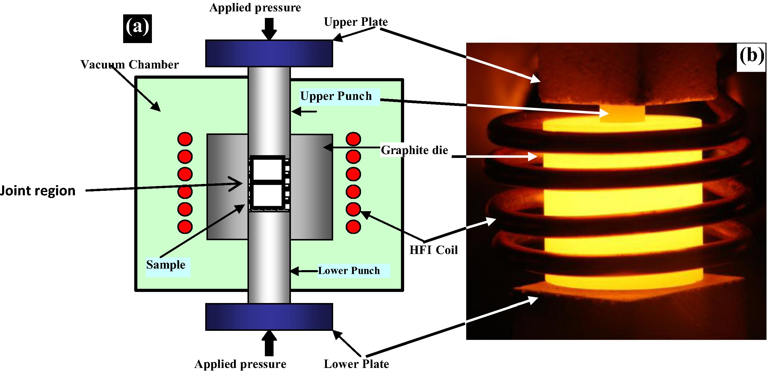
(a) Schematic diagram of high-frequency induction heating bonding apparatus and (b) real photo of the heated die.
The system is first evacuated to a vacuum level of 1 × 10⁻³ torr, and uniaxial pressure is applied. An induced current is then activated and maintained the required bonding temperature.
For metallurgical examination, each bonded sample was cut across the joint by wire cutting. One piece of each sample was mounted in Bakelite and the other piece was used for mechanical testing. The surfaces were polished to 1 μm finish in a diamond suspension. The microstructure of the joint was examined by Scanning Electron Microscope (SEM).
The samples were attached to SEM stage after wrapping with Cu tape for conduction. The samples were viewed by SEM FEI Quanta 200 operated at settings: Accelerating Voltage = 20 kV, Working Distance = 10 mm, Spot Size = 4.0. EDX analysis was performed on multiple regions in area, point and line modes using EDAX Genesis XM4 system attached to SEM. The elemental contents were calculated using standardless ZAF option. The images were recorded in back scattered imaging mode. The change in the composition was examined by Energy Dispersive Spectroscopy (EDS) (Voort, 2011). The shear joint strength was examined using Tinius Olsen shear tester in accordance with ASTM standard D1002 (ASTM Standard, 1999). The geometry of the shear testing is shown in Fig 2(a) where the actual image of the tester is shown in Fig 2(b). X-ray Photoelectron Spectroscopy (XPS) – JPS-9200 model was used to analyze the Ni coatings on Mg substrates and furthermore to analyze the second phase particles which were observed near the joint regions.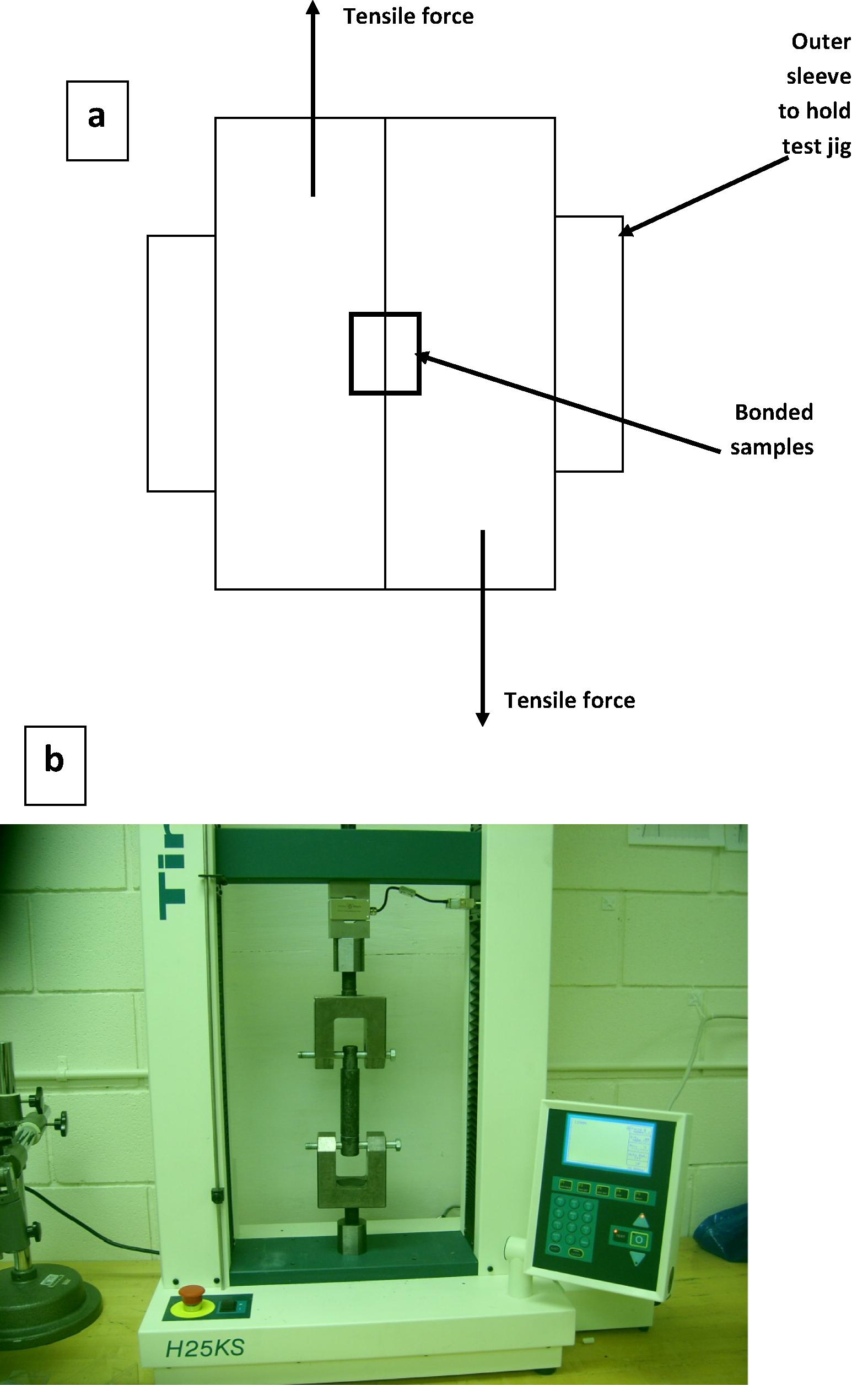
(a) Schematic of the shear test and joint geometry and (b) actual image of the shear test.
3 Results and discussion
3.1 Analysis of coatings
Fig 3 shows the distribution of Ni, Mg, O and C as a function of the coatings depth. Ion gun etching was used for depth profiling inside the XPS chamber. It can be seen that Ni concentration has the highest value which is about 35 atomic percent at a depth of 10 μm. Mg concentration at this depth is around 25 atomic percent. On the other hand it is understandable that the concentration of the contaminating elements like oxygen and carbon decreases with increasing depth and have the highest concentrations at the surface.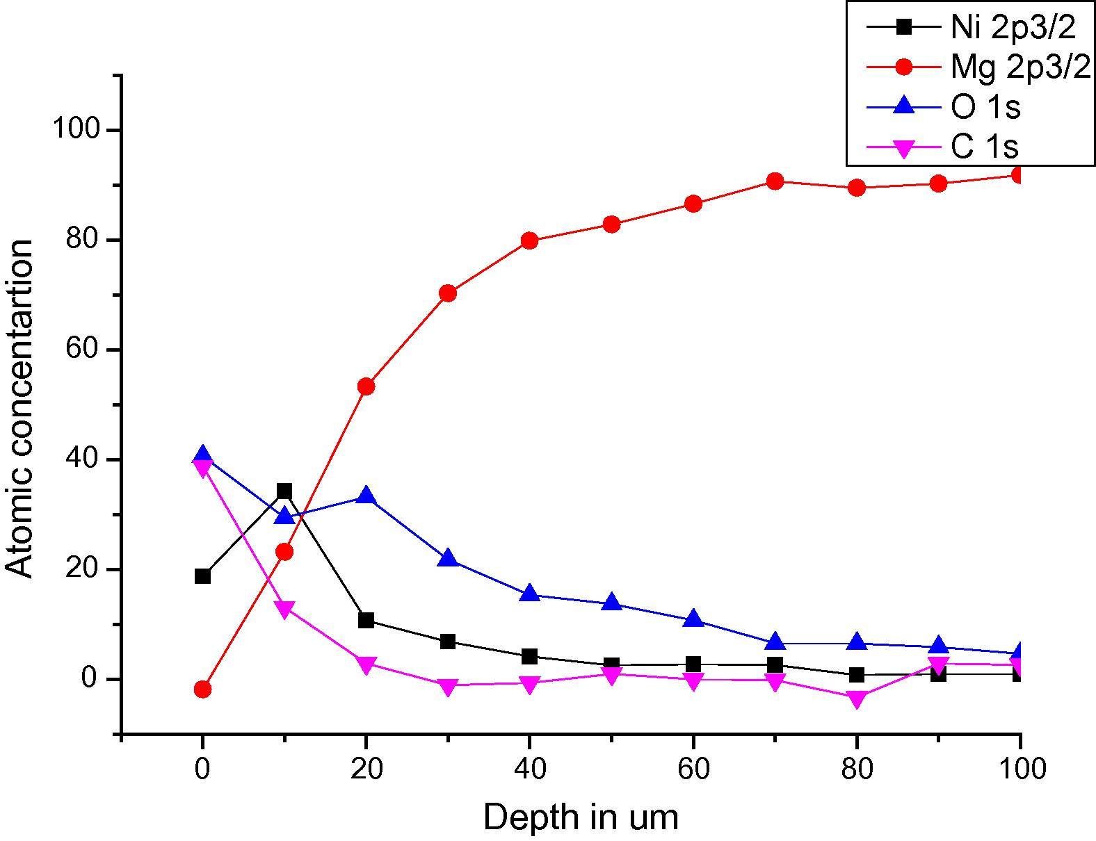
Distribution of elements after coating analyzed by XPS.
3.2 Mechanisms of bond formation
For the bond made at 5 min, SEM micrograph showed a rich Ni region at the joint of about 2 μm in width as shown in Fig 4, while the width of this region was reduced to about 1 μm for the bond made for 10 min as shown in Fig 5. Figs 6 and 7 show the joint region for bonds made at 15 and 20 min. On the other hand, it was not possible to observe rich Ni for bonds made at longer times. Fig 10 shows a low magnification micrograph of the bond made at 30 min where the joint line appeared to be dark which indicates that no rich Ni remains at the joint. In addition, the joint line for bonds made at 10 min and above was not continuous which suggest a complete dissolution of the Ni coatings occurs in some of interfacial locations at the joint regions. This could be due to the Ni/Mg eutectic reaction which starts forming liquid phase at a temperature of about 507 °C. EDS line scan was taken across the joint region for samples made at 5 and 15 min as shown in Figs 8 and 9. It was noticed that there is a reduction in Ni while increasing of Mg at the joint region. In addition, second phase particles were observed near the joint regions as shown in Fig 10 for the bond made at 30 min. Fig 11 shows a high magnification image of a second phase particle. X-ray Photoelectron Spectroscopy (XPS) was used to analyze this particle as shown in Fig 12. Narrow scan was taken at the binding energy regions for Ni (2p). It can be seen that the oxide peak disappeared after etching and only the peak of 852 eV remains. This peak has been reported previously to be attributed to the polycrystalline Mg2Ni compound (Lee et al., 2000; Mittal et al., 2004). XPS spectra of the second phase particle were also taken at the binding energy region of Mg as shown in Fig 13. It can be seen that after etching, the oxide peak disappeared and the metallic Mg (2p) was identified at a binding energy of 49.9 eV. Therefore, the XPS results suggest the presence of Mg2Ni IMC which is predicted in the Ni, Mg phase diagram.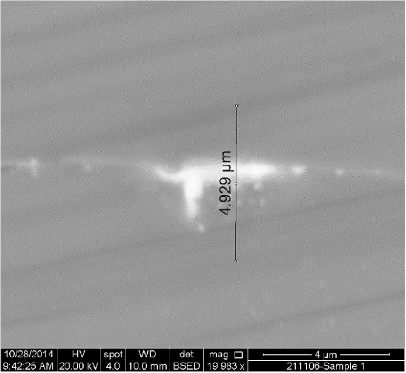
SEM image of the joint region for bond made at 5 min.
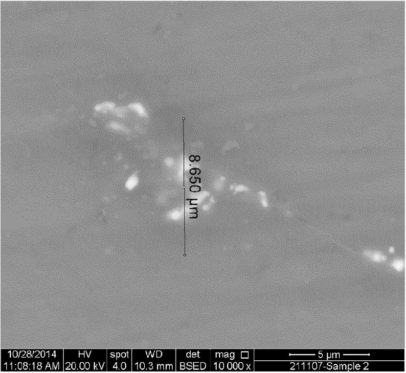
SEM image of the joint region for bond made at 10 min.
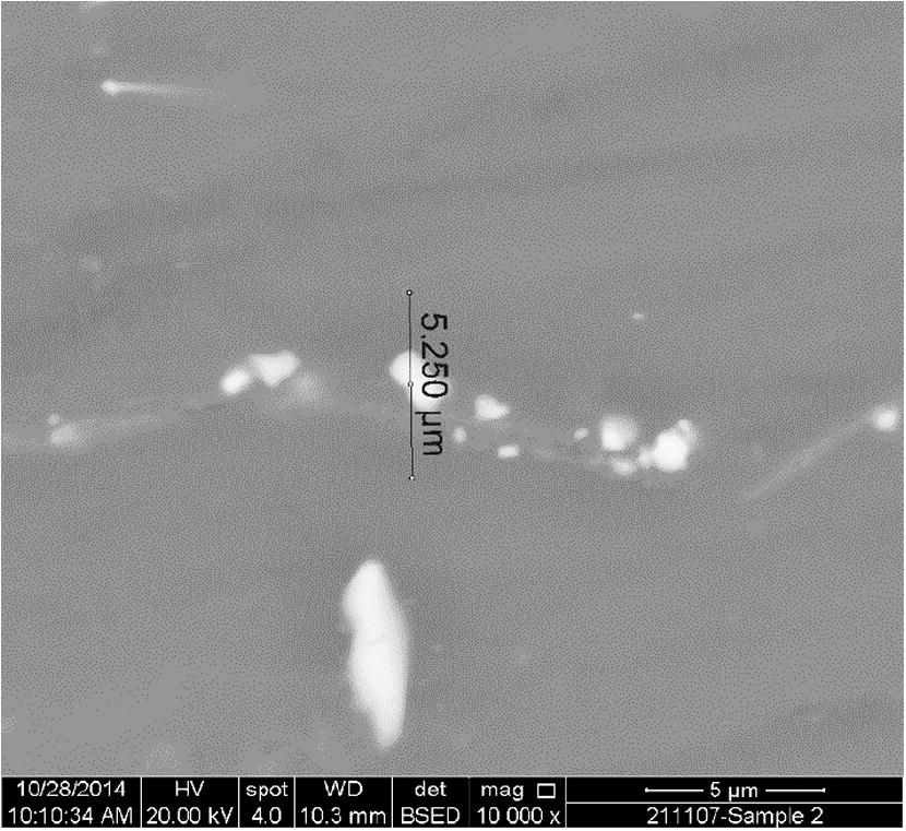
SEM image of the joint region for bond made at 15 min.
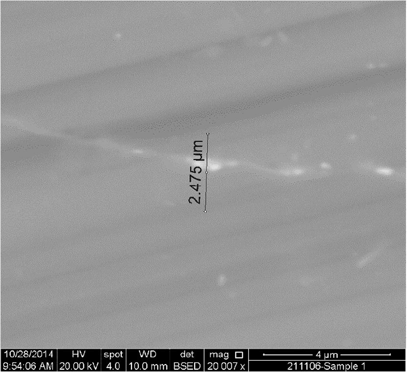
SEM image of the joint region for bond made at 20 min.
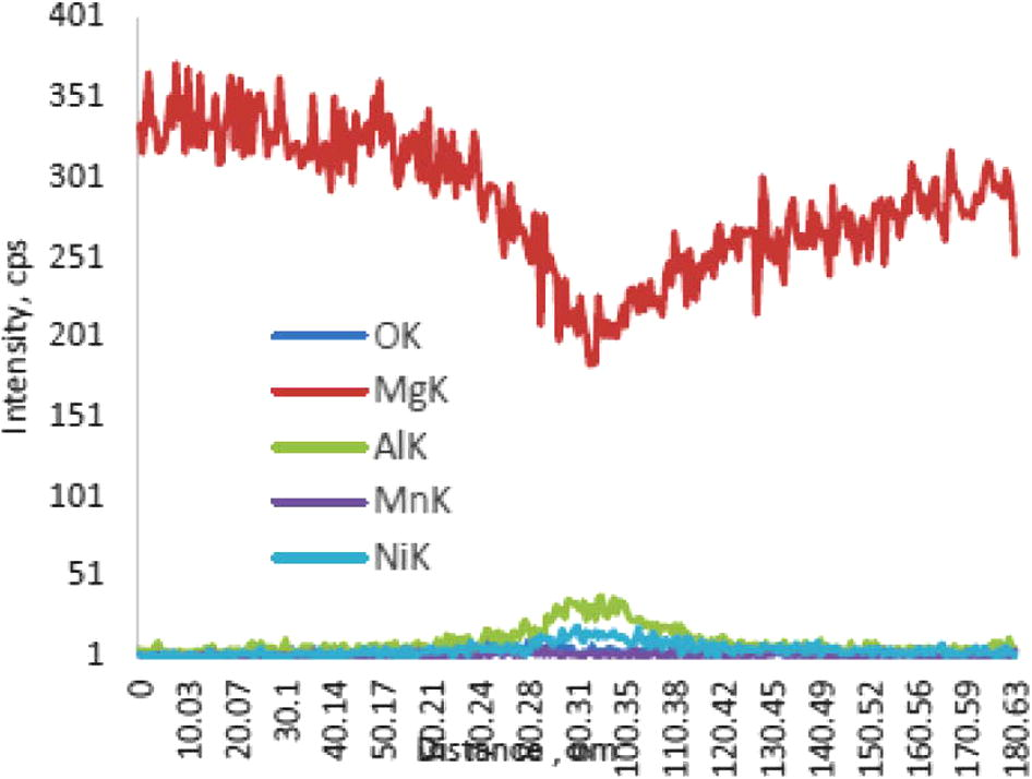
EDS line scan across the joint for different elements for bond made at 5 min.
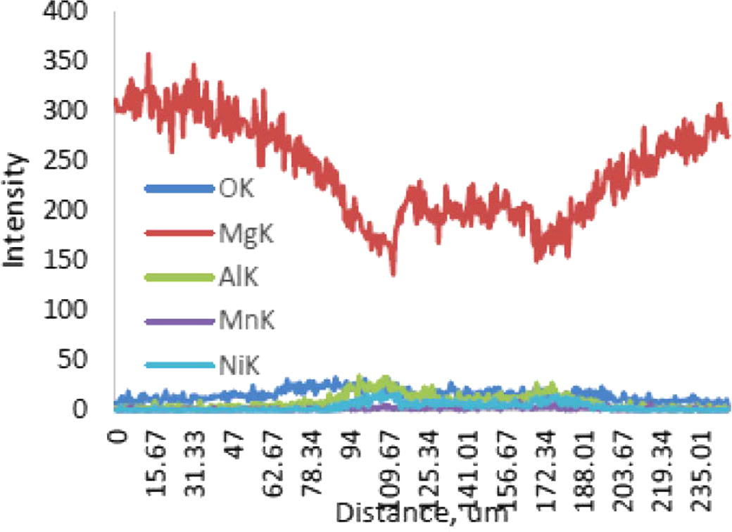
EDS line scan across the joint for different elements for bond made at 15 min.
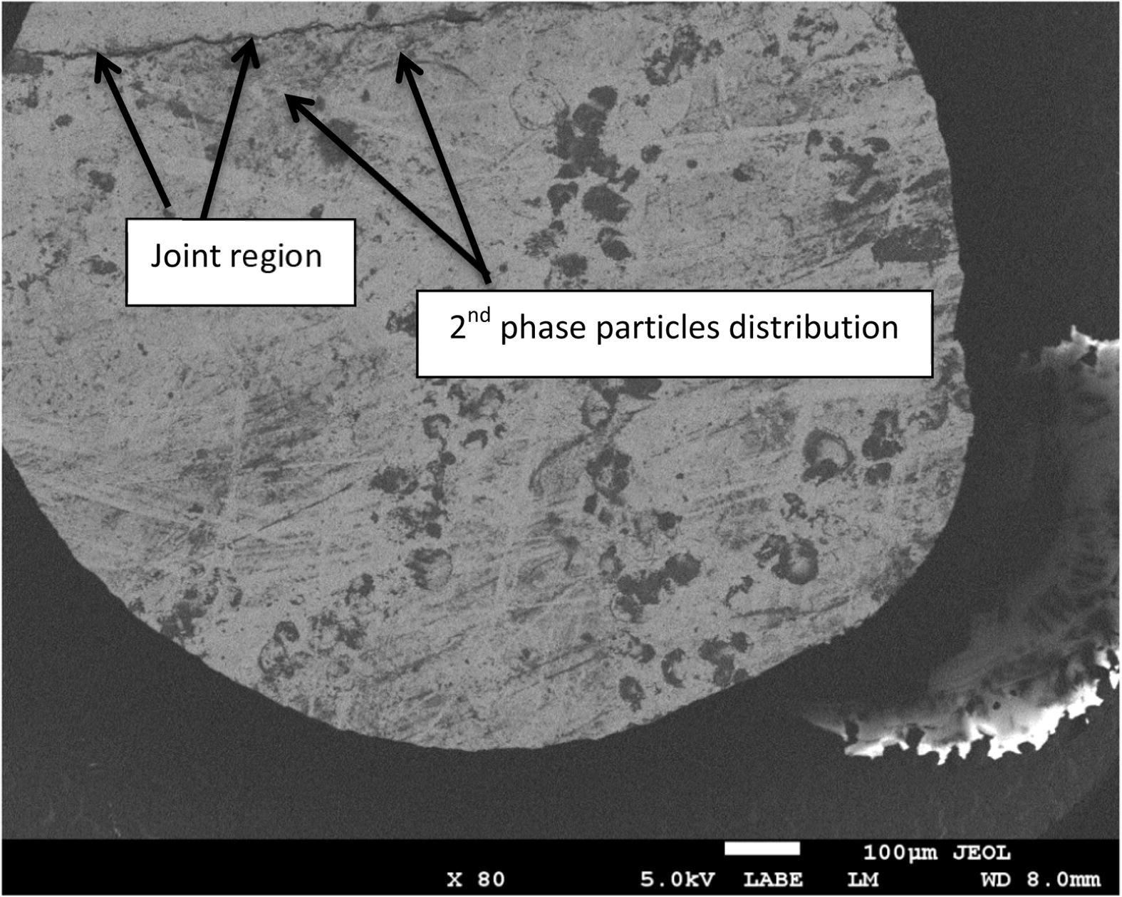
Low magnification image of the joint made at 30 min.
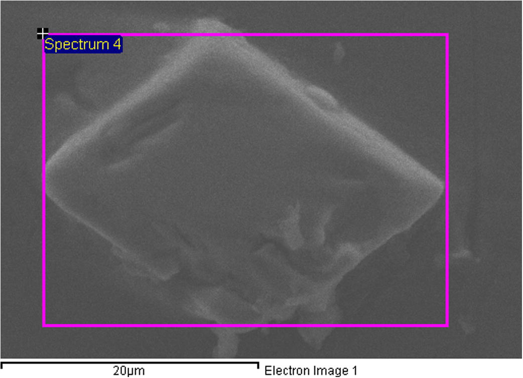
SEM image of a 2nd phase particle shown in bond made for 30 min.
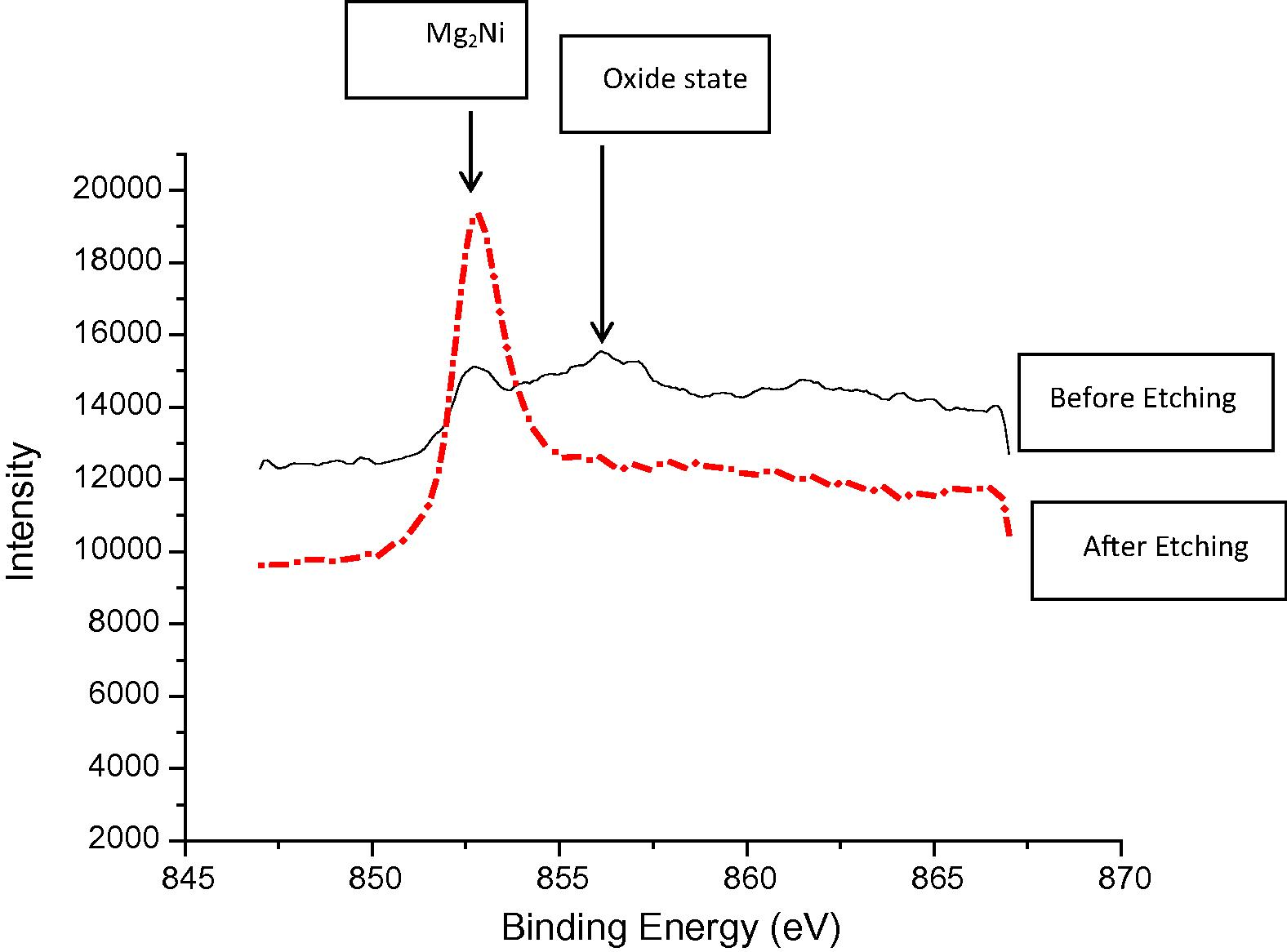
XPS narrow scan at the polycrystalline Mg2Ni binding energy region of the 2nd phase particle shown in Fig 11.
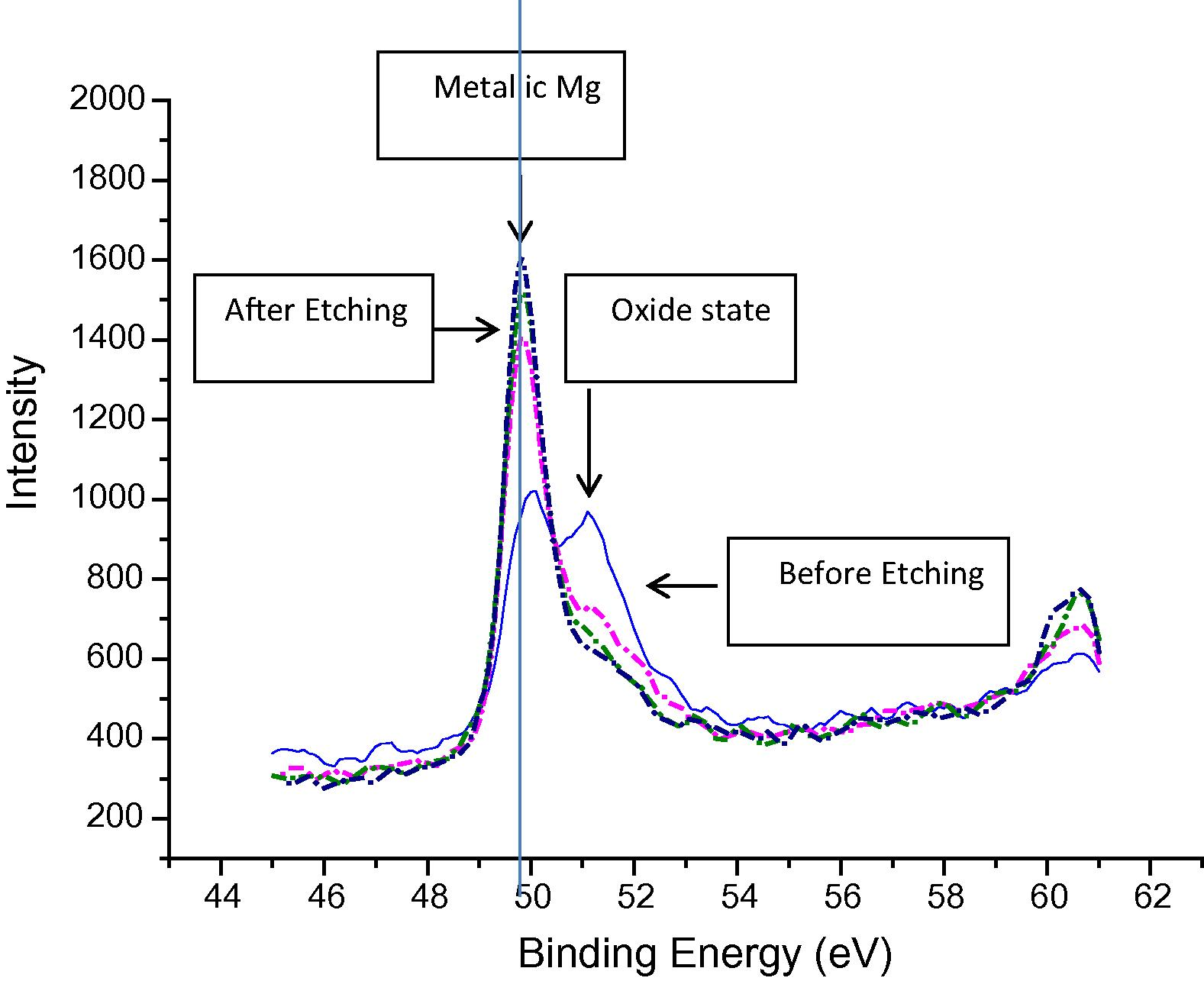
XPS narrow scan at Mg binding energy region of the 2nd phase particle shown in Fig 10.
Fig 14 shows SEM micrograph of the bond made at 20 min where the joint line can be identified at low magnification. It can be seen that the joint line is not continuous due to the complete homogenization of the joint region which is the ultimate stage for TLP bonding (Poku et al., 1988). Fig 15 shows a close up SEM image of the bond made at 20 min. The image shows that the joint region has different microstructures compared to the base material and that is due to the eutectic reaction between Mg alloy and Ni.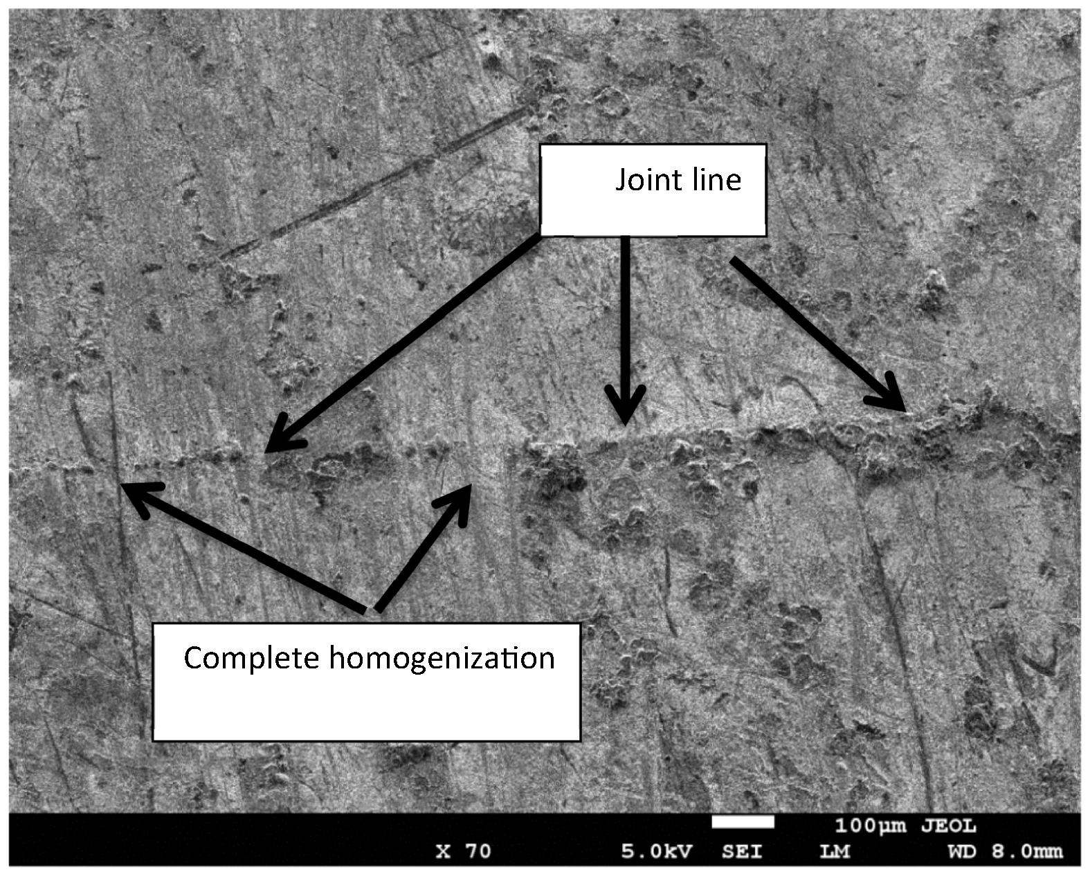
Image (SE mode) of the joint region for bond made at 20 min.
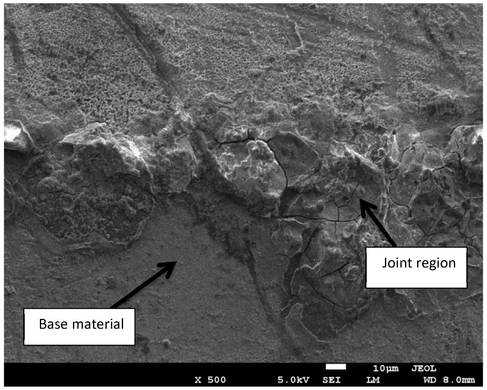
Close up image (SE mode) of the joint region for bond made at 20 min.
SEM micrographs were taken for the bond made at 20 min in two regions, one region is near the joint line and the other region is far away from the joint line as shown in Fig 16. Although the microstructure is same in the two regions of the magnesium alloy, it was obvious that the grain size is different. The difference in the grain size can be attributed to the TLP bonding as a welding process. The eutectic reaction which occurs in the joint region involves melting, diffusion and isothermal solidification. These processes are expected to increase the grain size of magnesium alloy near the joint when it solidifies. However, the grain size of the base material which is far from the joint region was not affected as shown in Fig 16(b). This is expected because TLP bonding is a welding process restricted to a narrow region near the joint line and should have no effect on the base material. The effect of welding process of magnesium alloy AZ31 on the grain size has been studied before and agreed with these observations (Fukumoto et al., 2007).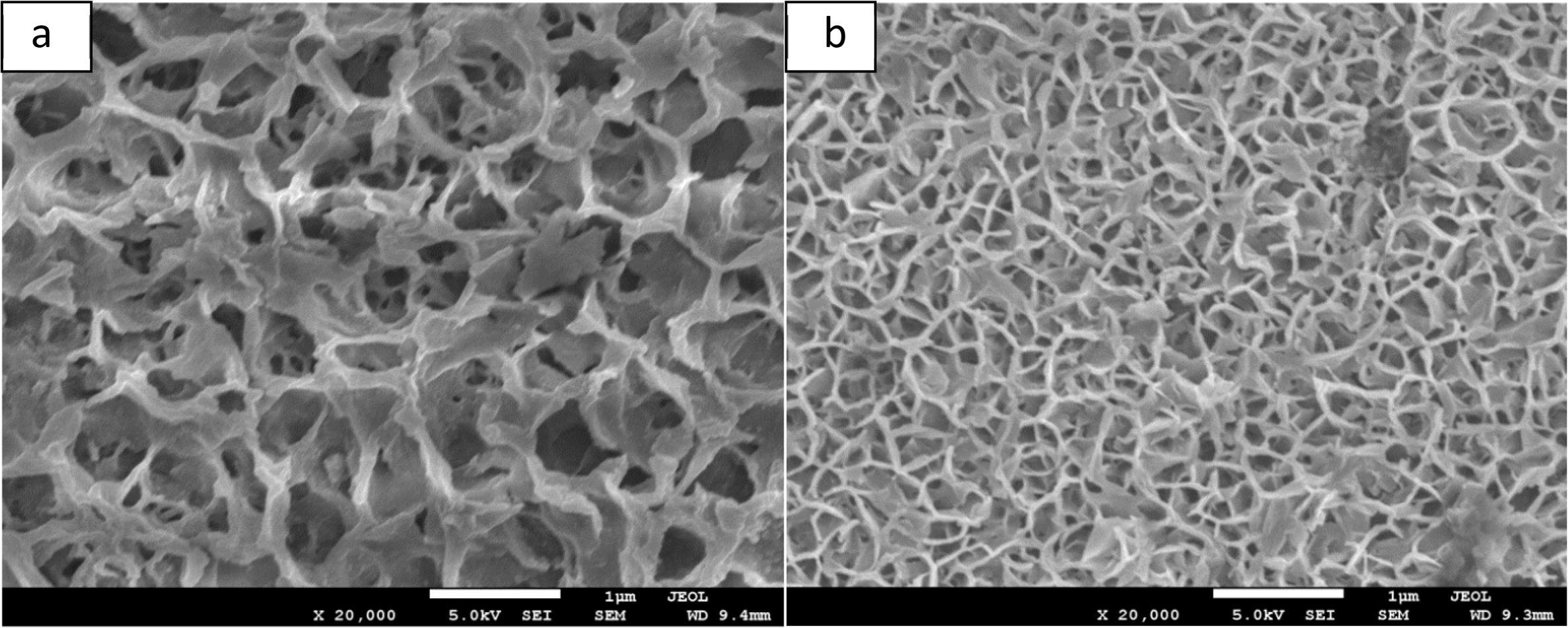
SEM images (SE mode) for the base material (a) near the joint and (b) away from the joint.
3.3 Shear strength measurements
Fig 17 shows the shear strength of the bonds as a function of bonding time. The bond made at 5 min gave shear strength of 21.5 MPa which is considered high for such short bonding time. For bond made at 10 min the shear strength was increased to 28.1 MPa. There was continuous increase of the shear strength with bonds made at 15 and 20 min. The measured shear strength gave 39 MPa and 46.2 MPa respectively. This gradual increase is attributed to the homogenization of the joint region which usually exceeded by isothermal solidification, eutectic reaction and dissolution of the Ni coatings. Nevertheless, at bonding time of 30 and 60 min it was observed that the shear strength was decreased and gave 43.7 and 38.7 respectively. This might be due to the grain coarsening and the increase in forming 2nd phase particles which have brittle structure. The maximum shear strength achieved was 46.2 MPa at bonding time of 20 min and this was higher than the maximum shear strength reported previously for bonding magnesium alloys together using Ni interlayer which was reported to be 36 MPa at 60 min bonding time (Jin and Khan, 2012).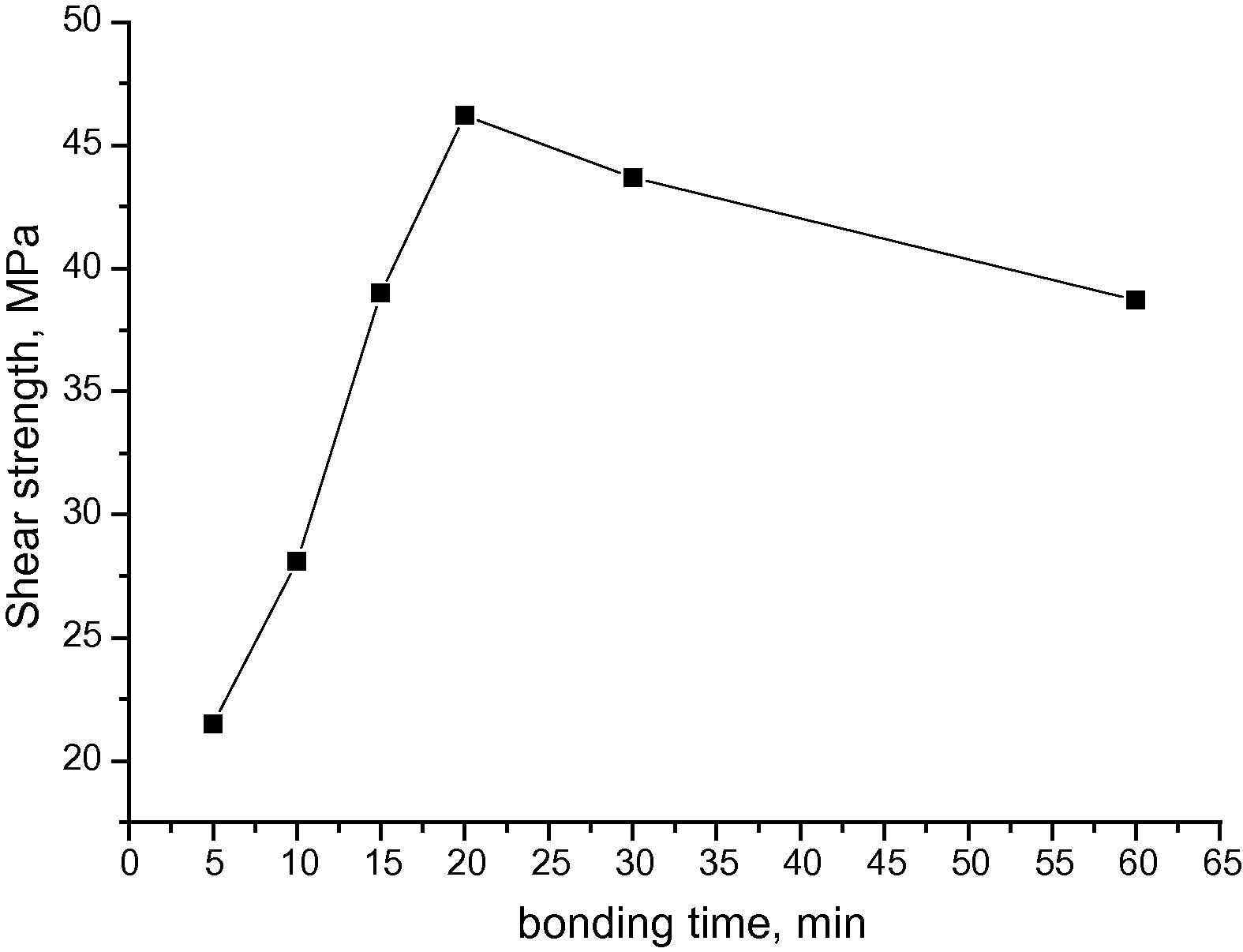
Shear strength of the bonded samples as a function of bonding time at 520 °C.
4 Conclusions
TLP bonding of Mg alloy AZ31 using Ni coatings was investigated in terms of microstructure and mechanical properties and the results gave the following conclusions:
-
For short bonding times, rich Ni was observed at the joint region by SEM. On another hand, Ni was proved to diffuse away with increasing bonding time and therefore, isothermal solidification was achieved. The present results are in conformity with other studies where time dependent process of TLP bonding was observed (Atieh and Khan, 2014; Khazaei et al., 2014; Lin et al., 2013).
-
At the selected bonding temperature and bonding pressure, the optimized bonding time of joining two magnesium alloy AZ31 together was found to be 20 min.
-
The brittle Mg2Ni particles observed by XPS for bonds made at longer times contributed to the weakening of the bond strength which aligned with the shear strength results.
-
It is a desire for TLP bonding to use minimal uniaxial pressure however the current facility in the lab provides a minimum of 8 MPa uniaxial pressure which limited our study on the TLP bonding using much lower applied pressure.
-
Although the IMC formation is usually inevitable, for the future studies it is recommended to use other coating metals such as Cu and Sn with proper bonding conditions and investigate the microstructure and strength of the AZ31 joints compared to Ni coatings.
Acknowledgment
The authors extend their appreciation to the Deanship of Scientific Research at King Saud University for funding this work through the Research Project No. NFG-14-03-27.
References
- Diffusion bonding of Al7075 to Ti–6Al–4V using Cu coatings and Sn–3.6Ag–1Cu interlayers. J. Alloy. Compd.. 2010;494(1–2):351-358.
- [Google Scholar]
- Transient liquid phase (TLP) bonding of Al7075 to Ti–6Al–4V alloy. Mater. Charact.. 2010;61(3):312-317.
- [Google Scholar]
- Transient liquid phase diffusion bonding under temperature gradient: modeling of the interface. Morphol. Acta Mater.. 2001;49:31-39.
- [Google Scholar]
- ASTM standard D1002, 1999. vol. 15.06. ASTM International, West Conshohocken.
- TLP bonding of Ti–6Al–4V and Mg–AZ31 alloys using pure Ni electro-deposited coats. J. Mater. Process. Technol.. 2014;214(12):3158-3168.
- [Google Scholar]
- Effect of post weld heat treatment on microstructures and mechanical properties of AZ31B friction welded joint. Mater. Trans.. 2007;48(1):44-52.
- [Google Scholar]
- Modeling of transient liquid phase bonding in binary systems—a new parametric study. Mater. Sci. Eng., A. 2007;445:493-500.
- [Google Scholar]
- Microstructural evolution during transient liquid phase bonding of Inconel 738LC using AMS 4777 filler alloy. Mater. Charact.. 2013;75:20-28.
- [Google Scholar]
- Effect of bonding time on microstructure and mechanical properties of transient liquid phase bonded magnesium AZ31 alloy. Mater. Des.. 2012;38:32-37.
- [Google Scholar]
- An investigation on microstructure and mechanical properties of Al7075 to Ti–6Al–4V transient liquid phase (TLP) bonded joint. Mater. Des.. 2012;38:19-25.
- [Google Scholar]
- TLP bonding of dissimilar FSX-414/IN738 system with MBF80 interlayer: prediction of solid/liquid interface location. Trans. Nonferrous Met. Soc. China. 2014;24(4):996-1003.
- [Google Scholar]
- The surface state of nanocrystalline and amorphous Mg Ni alloys prepared by mechanical alloying. J. Alloy. Compd.. 2000;313:258-262.
- [Google Scholar]
- Microstructure evolution and mechanical properties of transient liquid phase (TLP) bonded joints of TiAl intermetallics. Intermetallics. 2013;37:59-64.
- [Google Scholar]
- Solid state synthesis of Mg–Ni ferrite and characterization by XRD and XPS. J. Nucl. Mater.. 2004;335(3):302-310.
- [Google Scholar]
- Magnesium, properties – applications – potential. Mater. Sci. Eng., A. 2001;302:37-45.
- [Google Scholar]
- Modeling the transient liquid phase bonding behavior of a duplex stainless steel using copper interlayers. Mater. Sci. Eng., A. 2004;385(1–2):220-228.
- [Google Scholar]
- A study of the transient liquid phase bonding process applied to a Ag/Cu/Ag sandwich joint. Metall. Trans. A. 1988;19A:675-685.
- [Google Scholar]
- Robert, E., Brown, B., 2002. Magnesium Wrought and Fabricated Products Yesterday, Today, and Tomorrow. The Minerals, Metals & Materials Society, Magnesium Technology.
- Analytical modeling of transient liquid phase (TLP) diffusion bonding when a temperature gradient is imposed. Acta Mater.. 1999;47(13):3551-3560.
- [Google Scholar]
- Diffusion bonding in superplastic magnesium alloys. Mater. Sci. Eng.. 2003;A339:328-333.
- [Google Scholar]
- Transient liquid phase bonding of magnesium alloy (Mg–3Al–1Zn) using aluminum interlayer. Mater. Sci. Eng., A. 2005;391:29-33.
- [Google Scholar]
- Electromagnetic shielding properties of magnesium and magnesium alloys. J. Mater. Eng.. 2013;1:52-57.
- [Google Scholar]


