Translate this page into:
MHD mixed convection flow over a permeable non-isothermal wedge
*Corresponding author prasadkv2007@gmail.com (K.V. Prasad) prasadkv2000@yahoo.co.in (K.V. Prasad)
-
Received: ,
Accepted: ,
This article was originally published by Elsevier and was migrated to Scientific Scholar after the change of Publisher.
Peer review under responsibility of King Saud University.

Available online 22 February 2013
Abstract
Numerical solutions are obtained for the hydro-magnetic mixed convection boundary layer flow of an electrically conducting fluid over a non-isothermal wedge in the presence of variable thermal conductivity. The effects due to viscous dissipation, internal heat generation/absorption, thermal radiation, Joule heating and stress work are included. The governing partial differential equations of the problem, subjected to the appropriate boundary conditions are solved numerically by an efficient finite difference scheme. Numerical calculations are carried out for several sets of values of the dimensionless parameters and a careful study of the results obtained reveal that the flow field is influenced appreciably by the applied magnetic field in addition to the other parameters. Numerical results for the velocity and temperature fields, the local skin-friction coefficient and the local Nusselt number are presented graphically and discussed. To validate the numerical method, comparisons are made with the available results in the literature as special cases and the results are found to be in good agreement. The results obtained reveal many interesting behaviors that warrant further study of the flow and heat transfer characteristics over the permeable wedge.
Keywords
Convective heat transfer
MHD flow
Variable thermal conductivity
Viscous dissipation
Finite difference scheme
Non-isothermal wedge
Nomenclature
- A
-
positive constant
- C
-
positive constant
- B0
-
external imposed magnetic field
- Cp
-
specific heat at constant pressure
- Cf
-
local skin friction coefficient
- Ec
-
Eckert number
- f
-
dimensionless steam function
- fo
-
wall mass transfer parameter
- g
-
acceleration due to gravity
- Grx
-
local Grashof number
- K
-
thermal conductivity
- k∞
-
thermal conductivity away from the surface
- K
-
absorption coefficient
- m
-
pressure gradient parameter
- Nr
-
thermal radiation parameter
- Nux
-
local Nusselt number
- Pr
-
Prandtl number
- qr
-
the radiative heat flux
- Q0
-
heat generation/absorption coefficient
- Rex
-
local reynolds number
- T
-
the temperature
- Tw
-
condition at the surface
- T∞
-
free stream surface temperature
- u
-
velocity component in the x-direction
- U∞
-
potential flow or free stream velocity
- v
-
velocity component in y-direction
- v0
-
suction or injection velocity
- x
-
coordinate along the wedge
- y
-
coordinate normal to the wedge
- α
-
thermal diffusivity
- B0
-
coefficient of thermal expansion
- B1
-
angle factor of the wedge
- B
-
heat source/sink parameter
- η
-
pseudo similarity variable
- λ
-
mixed convection parameter
- ν
-
kinematic viscosity
- ρ
-
density
- ɛ
-
thermal conductivity parameter
- ξ
-
magnetic variable
- Ω
-
total angle of the wedge
- θ
-
dimensionless temperature
- σ
-
electric conductivity
- σ∗
-
Stephen–Boltzmann constant
- ψ
-
stream function
Greek Symbols
1 Introduction
In recent years a great deal of interest has been generated to study the problem of magneto-hydrodynamic (MHD) incompressible, steady viscous flow over a non-isothermal wedge due to its extensive practical applications in technological processes; such as MHD power generator designs, design for cooling of nuclear reactors, construction of heat exchangers, installation of nuclear accelerators and blood flow measurement techniques. Watanabe (1978, 1986) studied theoretically the characteristics of MHD boundary layer flow past a flat plate with/without pressure gradient. Watanabe and Pop (1994) extended the work of Watanabe (1978) to thermal field. Yih (1999, 1998) investigated the effects of viscous dissipation and the work done by stress on the heat transfer characteristics. Chandrasekar and Baskaran (2007) studied the effects of transverse magnetic field, viscous dissipation, stress work, shear stress and surface heat transfer over a non-isothermal wedge. An approximate numerical solution for thermal stratification on MHD steady laminar boundary layer flow over a wedge with suction or injection was investigated by Anjali Devi and Kandasamy (2003). Pal and Mondal (2009) investigated the combined effects of thermal radiation and temperature-dependent viscosity on the momentum and heat transfer in the presence of magnetic field. Recently, Loganathan and Puvi Arasu (2010) analyzed the effects of thermophoresis particle deposition on the non-Darcy mixed convective heat and mass transfer past a porous wedge in the presence of suction/blowing.
The physical situation discussed by Watanabe (1978) is one of the possible cases. Another physical phenomenon is the case in which the difference between the surface temperature and the free stream temperature namely (Tw − T∞) is appreciably large. The findings of such a physical phenomenon will have a definite bearing on technological industries: the problem of mixed convection flow over a heated vertical plate is of considerable interest. There are many examples of relevant studies in the articles reported by (Ali and Al-Youself, 1998; Chen, 1999; Kumari et al., 2001; Patil et al., 2009). Mixed convection heat transfer at a stretching sheet with variable temperature and linear velocity was investigated by Vajravelu (1994). Similar analyses were performed numerically by Chen and Strobel (1980) and Moutsoglou and Chen (1980) for fluids under different physical situations.
All the above researchers restricted their analyses to hydromagnetic flow and heat transfer over a vertical plate. The role of thermal radiation on the flow and heat transfer processes is of major importance in the design of many advanced energy conversion systems. In view of this, Raptis (1998) studied the thermal radiation and free convection flow through a porous medium. Chamkha et al. (2003) generalized the work of Yih (1999) by considering the effects of suction and thermal radiation. In these studies, the thermo-physical properties of the ambient fluids are assumed to be constant. However, it is well known that these properties may change with temperature, especially the thermal conductivity. Available literature on variable thermal conductivity and thermal radiation (Chiam, 1996; Raptis, 1998; Prasad et al., 2000; Chamkha et al., 2003; Datti et al., 2004; Subhas Abel et al., 2005; Aydın and Kaya, 2008) shows that not much work has been carried out on mixed convection flow over a non-isothermal permeable wedge with variable thermal conductivity. Furthermore, the study of convection heat transfer around and through shapes like spheres, cones, and wedges has been very active in the past century. The flow of heat around these objects has applications in many fields including the design of spacecraft, nuclear reactors, and many types of transformers and generators. Vajravelu and Nayfeh (1992) investigated free convection in heat-generating fluids around both cones and wedges. The last few decades have also shown a major increase in the research of convective heat transfer through porous media. This is because it is applicable to topics such as nuclear waste storage, ground-water pollution, chemical separation processes, and many other areas of interest.
In view of this, we analyze in this paper the MHD mixed convection flow over a permeable non-isothermal wedge in the presence of variable thermal conductivity. Further, we include the effects of internal heat generation/absorption, viscous dissipation, and work done by stress. While deriving the basic equations, a temperature dependent heat source/sink term is added and the Roseland approximation for the thermal radiation term is assumed. The governing coupled, non-linear partial differential equations for the flow and heat transfer are solved numerically by an implicit finite difference scheme known as Keller-box method.
2 Mathematical formulation
Consider a steady, two-dimensional, viscous, incompressible, mixed convection boundary layer flow over a permeable non-isothermal wedge in the presence of thermal radiation and heat generation/absorption. Let the x-axis be taken along the wall of the wedge and y-axis normal to it (see Fig. 1). A uniform magnetic field of strength B0 is applied parallel to y-axis. Fluid suction or injection is imposed at the surface of the wedge and the surface of the wedge is maintained at a variable temperature proportional to the power of the distance, i.e.,
as shown in Fig. 1. The induced magnetic field is assumed to be uniform and is in the direction normal to the surface. It is also assumed that the magnetic Reynolds number is small and the electric field due to polarization of charges is negligible. All the thermo-physical properties of the fluid are assumed to be constant except the density variation in the body force term and the thermal conductivity. Effects due to viscous dissipation, Joule heating, and the work due to stress are included. Under these assumptions and the usual Boussinesq approximation, the governing boundary layer equations for the conservation of mass, momentum and energy can be written as
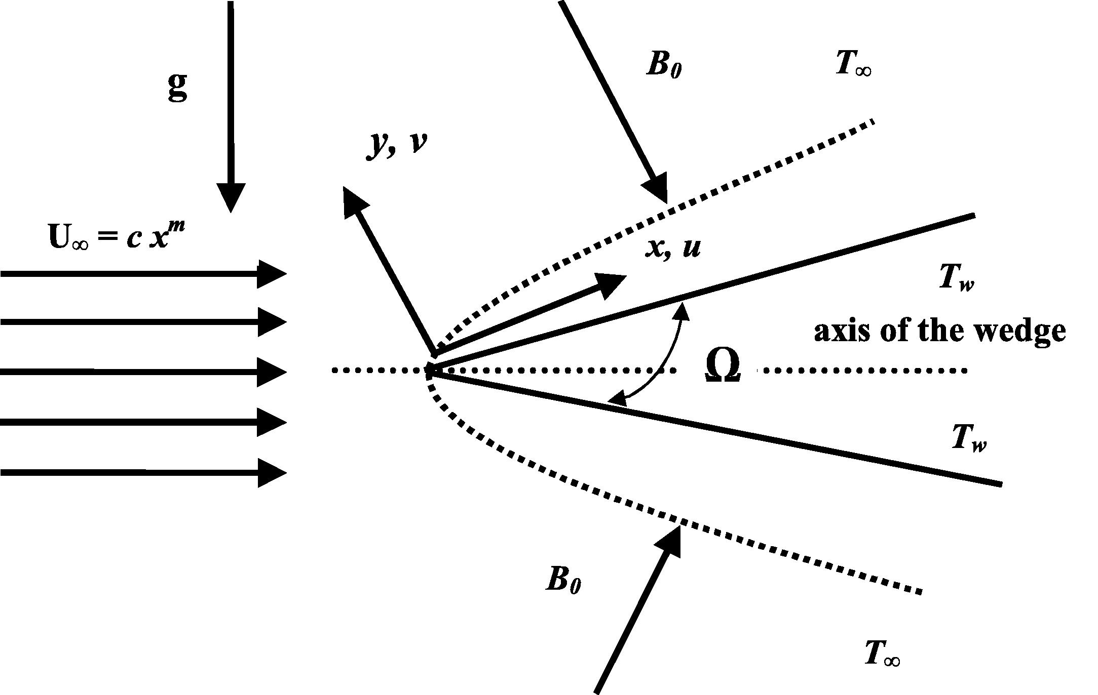
Flow analysis along the wall of the edge.
The physical boundary conditions for the problem are given by
Here ɛ is a small parameter known as the variable thermal conductivity parameter and ΔT = Tw − T∞ is the surface temperature. In addition, the radiative heat flux qr is employed in accordance with the Roseland approximation.
With the help of (6) and (7), the Eq. (3) can be written as
Defining the stream function in the usual way such that u = ∂ψ/∂y and, v = −∂ψ/∂x and substituting the following dimensionless variables (Chamkha et al., 2003; Pal and Mondal, 2009).
The parameters
are the Prandtl number, the thermal radiation parameter, the heat source/sink parameter, the Eckert number and the mixed convection parameter, respectively, and are defined by
The dimensionless forms of the boundary conditions are
In the above equations the local Reynolds number is defined as follows:
3 Numerical procedure
The Eqs. (10) and (11) are highly non-linear, coupled partial differential equations. Exact analytical solutions are not possible for the complete set of equations subject to the boundary conditions (13) and hence we use an efficient implicit finite difference for the solution process. The implicit finite difference scheme discussed by Cebeci and Bradshaw (1984) is chosen for this purpose because it has been proven to be more than adequate to give accurate results for coupled boundary layer equations. The coupled boundary value problem of third order in f and second order in θ, is reduced to a system of five simultaneous differential equations of first order with respect to η by assuming . Initially all first order derivatives with respect to ξ are replaced by two-point backward difference formulae of the form. denoting an approximate value of f at the grid point . To solve this system of equations we require five initial conditions while we have only two initial conditions and one initial condition . The other two initial conditions which are not prescribed; however, the values of are known for η at infinity. Hence, we employ the numerical Keller-Box scheme where these two boundary conditions are utilized to produce two unknown initial conditions at η = 0. To select η∞, we begin with some initial guess value and solve the boundary value problem for a set of parameters to obtain . Thus we start with the initial approximation as and then let α and β be the correct values of , respectively. We integrate the resulting system of five differential equations using fourth order Runge–Kutta method and obtain the values of , respectively. Finally the problem has been solved numerically using a second order finite difference scheme known as the Keller-box method (Prasad et al., 2010, 2011). The solution process is repeated with another larger value of η∞ until two successive values of agree up to the desired decimal level signifying the limit of the boundary along η. The last value of η∞ is chosen as an appropriate value for that set of parameters.
The numerical solutions are obtained in four steps as follows:
-
reduce Eqs. (10) and (11) to a system of first-order equations;
-
write the difference equations using central differences;
-
linearize the algebraic equations by Newton’s method, and write them in matrix–vector form; and
-
solve the linear system by the block tri-diagonal elimination technique.
For each value of ξ, we get a set of algebraic equations. With each of the non-linear terms evaluated at the previous iteration, the algebraic equations are solved with iteration by the well-known Thomas algorithm. This process is repeated for the next ξ value and the problem is solved line by line until the desired ξ value is reached. For the sake of brevity further details on the solution process are not presented here. It is also important to note that the computational time for each set of input parameters should be as short as possible. Since the physical domain in this problem is unbounded, whereas the computational domain has to be finite, we apply the far field boundary conditions for the pseudo-similarity variable η at a finite value denoted by ηmax. We ran our bulk of computations with ηmax = 7, which is sufficient to achieve asymptotically the far field boundary conditions for all values of the parameters considered. For numerical calculations, a uniform step size of Δη = 0.005, and Δξ = 0.001 is found to be satisfactory and the solutions are obtained with an error tolerance of 10−6 in all the cases. To assess the accuracy of the present method, comparison of the skin friction and the wall-temperature gradient between the present results and the previously published results are presented, for several special cases in which the buoyancy parameter and the variable thermal conductivity parameter are neglected (see Tables 1 and 2).
m
Present results
Yih (1999)
Cebeci and Bradshaw (1984)
Chamkha et al. (2003)
Pal and Mondal (2009)
−0.05
0.213442
0.213484
0.21351
0.213802
0.213484
0.0
0.333228
0.332057
0.33206
0.332206
0.332206
0.3333
0.757158
0.757448
0.75745
0.757586
0.757586
1.0
1.232578
1.232588
1.23259
1.232710
1.232588
Pr = 0.733
Pr = 1.0
ξ
Present results
Yih (1999)
Watanabe and Pop (1994)
Chamkha et al. (2003)
Pal and Mondal (2009)
Present results
Yih (1999)
Watanabe and Pop (1994)
Chamkha et al. (2003)
Pal and Mondal (2009)
0.0
0.297656
0.297526
0.29755
0.297600
0.297526
0.332028
0.332057
0.33206
0.332173
0.332057
0.5
0.357473
0.357022
0.35699
0.357040
0.355269
0.405721
0.402864
0.40280
0.403103
0.401527
1.0
0.388155
0.382588
0.38336
0.383191
0.377470
0.435844
0.433607
0.43446
0.433901
0.428506
1.5
0.403345
0.398264
0.39959
0.399980
0.390609
0.454605
0.452634
0.45413
0.452808
0.444571
2.0
0.413890
0.409168
0.41091
0.409450
0.399658
0.467772
0.465987
0.46798
0.466111
0.455700
4 Results and discussion
In order to analyze the physical model, numerical computations are carried out by the method described above for several sets of values of the pressure gradient parameter m, suction or injection parameter fw, the magnetic parameter ξ, the mixed convection parameter λ, the Prandtl number Pr, the thermal radiation parameter Nr, heat source/sink parameter, variable thermal conductivity parameter ɛ, and the Eckert number Ec. Since it is not possible to present the results here for all possible permutations and combinations of all the physical parameters, we focus our attention on the effect of new parameters on the flow and heat transfer fields. The numerical results are presented in Figs. 2–13. These figures depict the changes in the wall-normal velocity and the fluid temperature. Changes in the skin friction and the wall-temperature gradient for several sets of the pertinent parameters are recorded in Tables 3 and 4.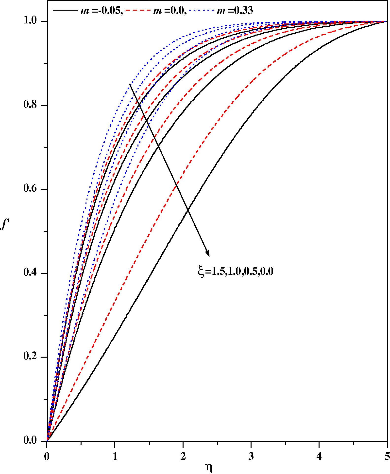
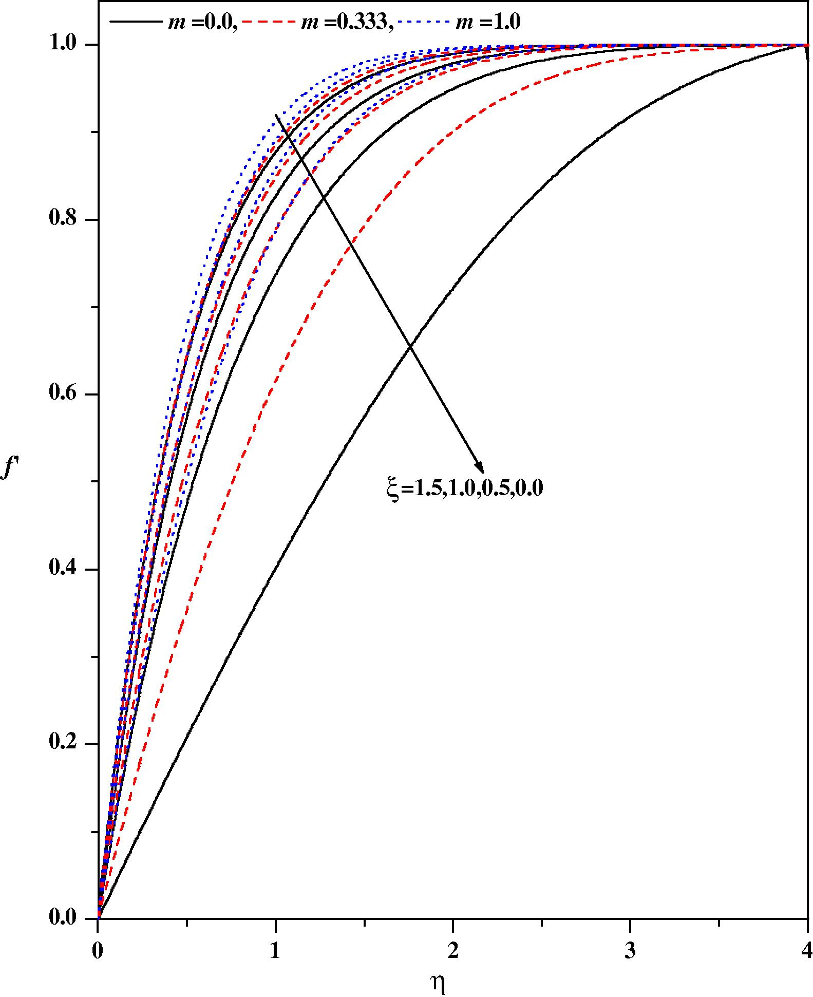
Wall-normal velocity profiles for different values of m and ξ with λ = 0.0 Nr = 0.0, fw = 0.0, ε = 0.0, Pr = 1.0, Ω = 30°, β = 0.0.
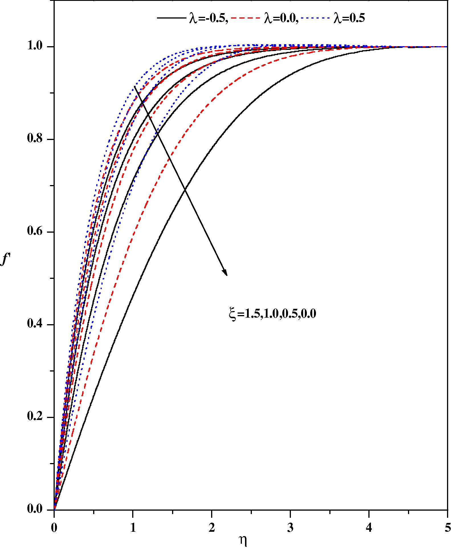
Wall-normal velocity profiles for different values of λ and ξ with Ec = 0.1, fw = 0.5, ε = 0.1, Pr = 1.0, β = −1.0, Ω = 30°, m = 0.333, Nr = 0.5.
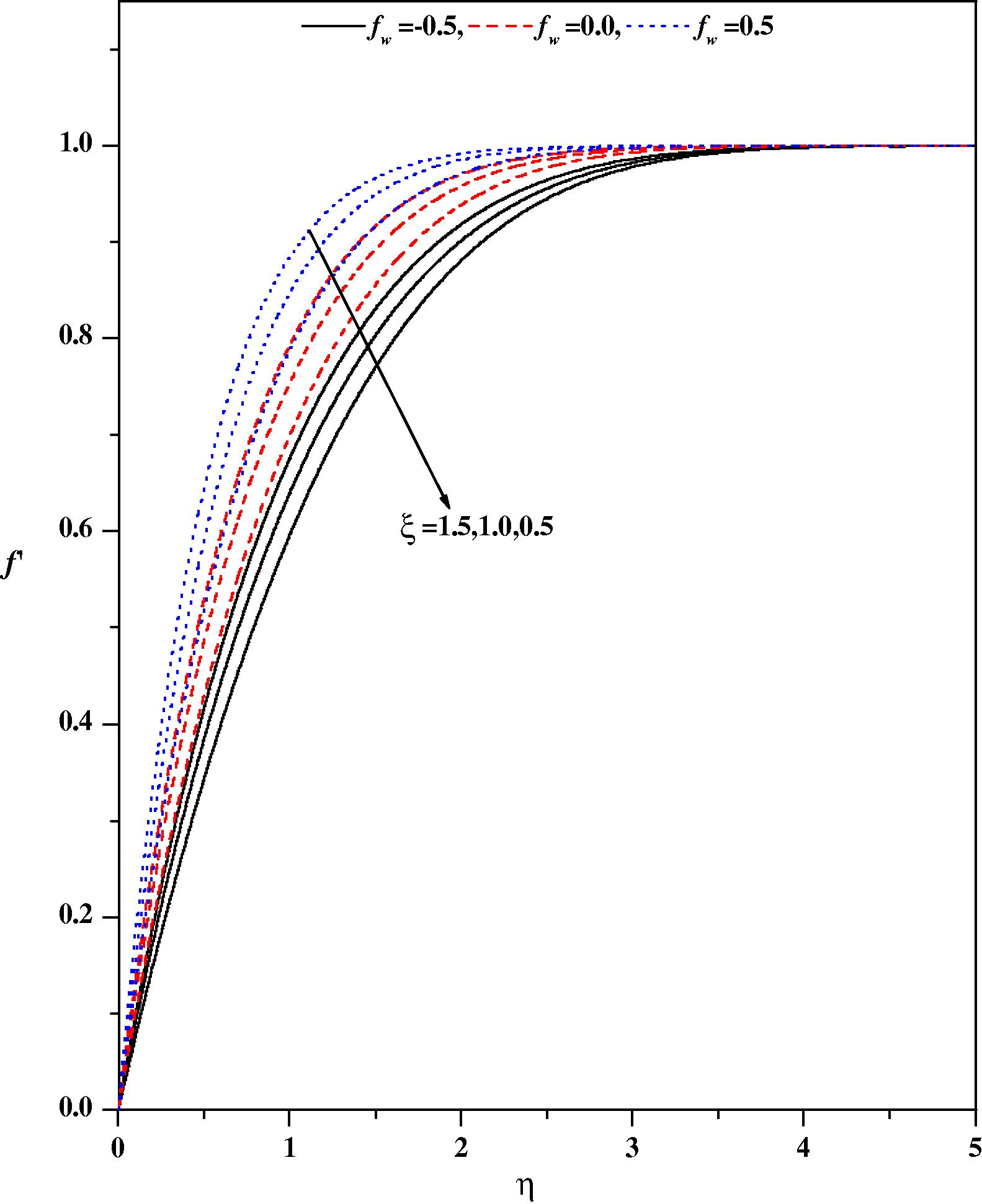
Wall-normal velocity profiles for different values of fw and ξ with Ec = 0.1, λ = 0.1, ε = 0.1, Pr = 1.0, β = −1.0, Ω = 30°, m = 0.333, Nr = 0.5.
Wall-normal velocity profiles for different values of m and ξ with Nr = 0.2, λ = 0.1, Ec = 0.0, fw = 0.5, ε = 0.1, Ω = 30°, Pr = 1.0, β = −0.1.
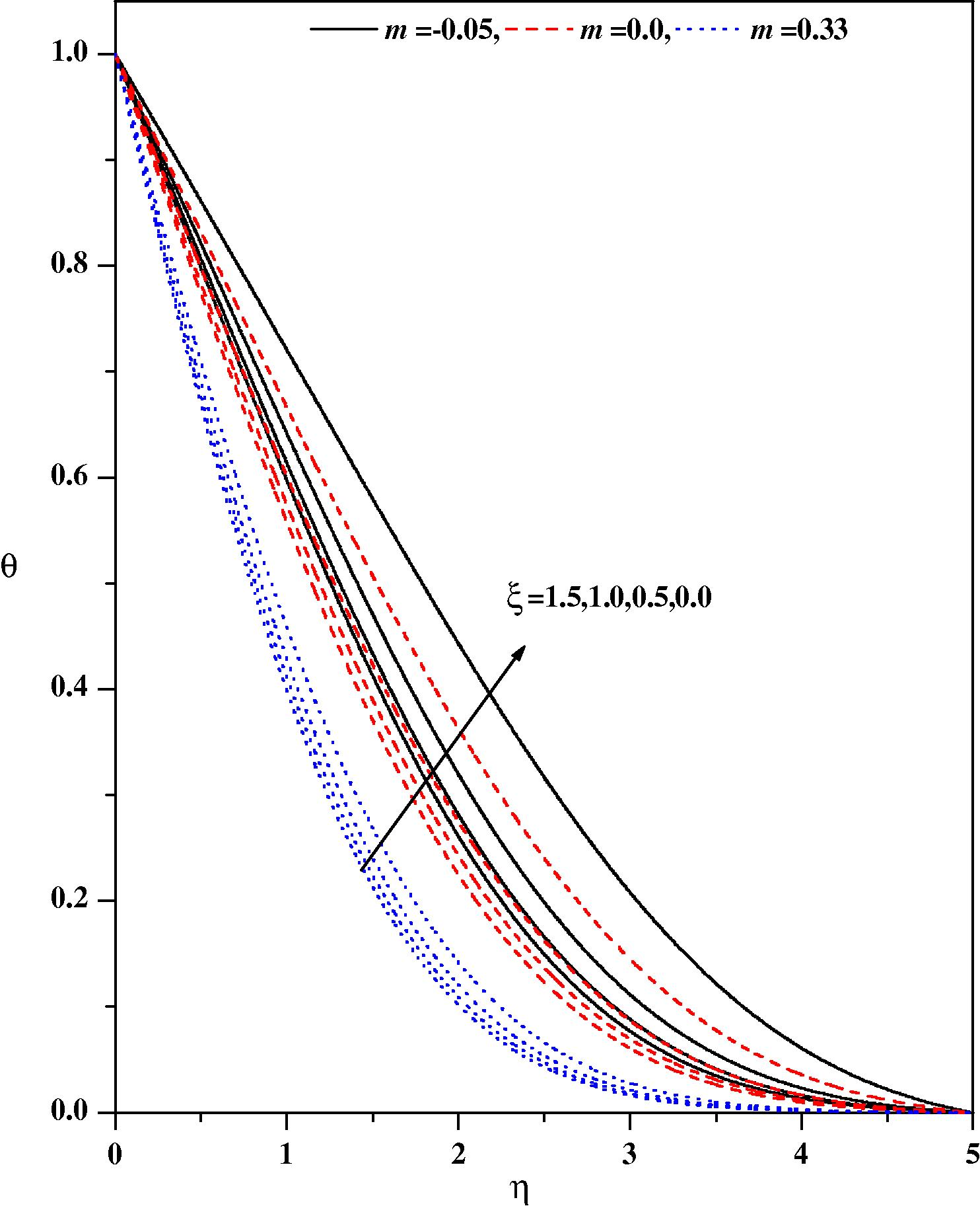
Temperature profiles for different values of m and ξ with Ω = 30°, λ = 0.0, Ec = 0.0, Nr = 0.0, fw = 0.0, ε = 0.0, Pr = 1.0, β = 0.0.
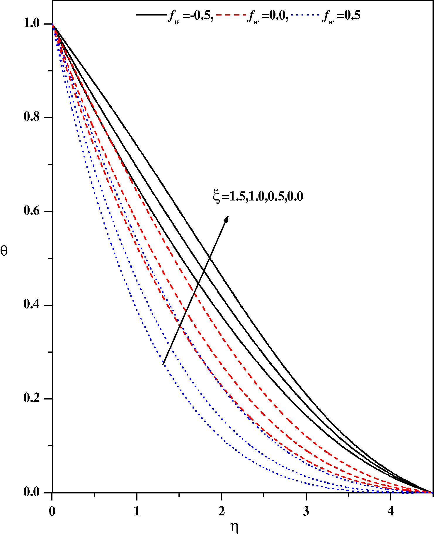
Temperature profiles for different values of fw and ξ with Nr = 0.5, λ = 0.1, ε = 0.1, Pr = 1.0, β = −1.0, m = 0.33, Ω = 30°, Ec = 0.1.
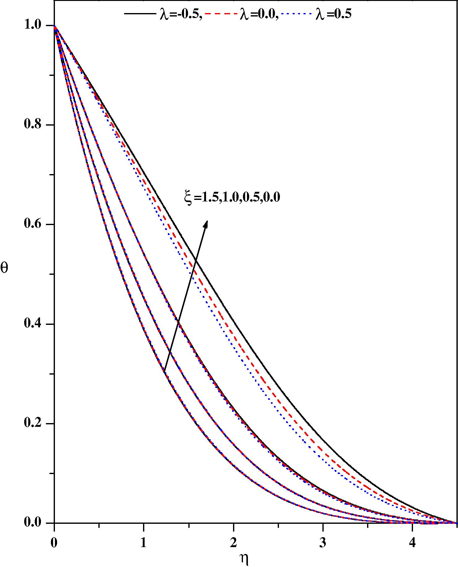
Temperature profiles for different values of λ and ξ with Nr = 0.5, fw = 0.5, ε = 0.1, Pr = 1.0, β = −1.0, m = 0.33, Ω = 30°, Ec = 0.1.
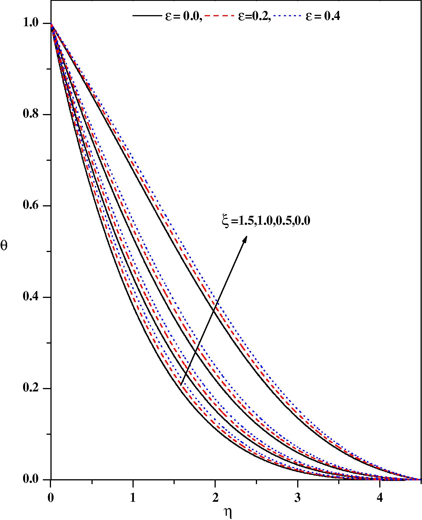
Temperature profiles for different values of ε and ξ with Nr = 0.5, fw = 0.5, Ec = 0.1, Ec = 0.01, m = 0.333, β = 0.1, Ω = 30°, λ = 0.1.
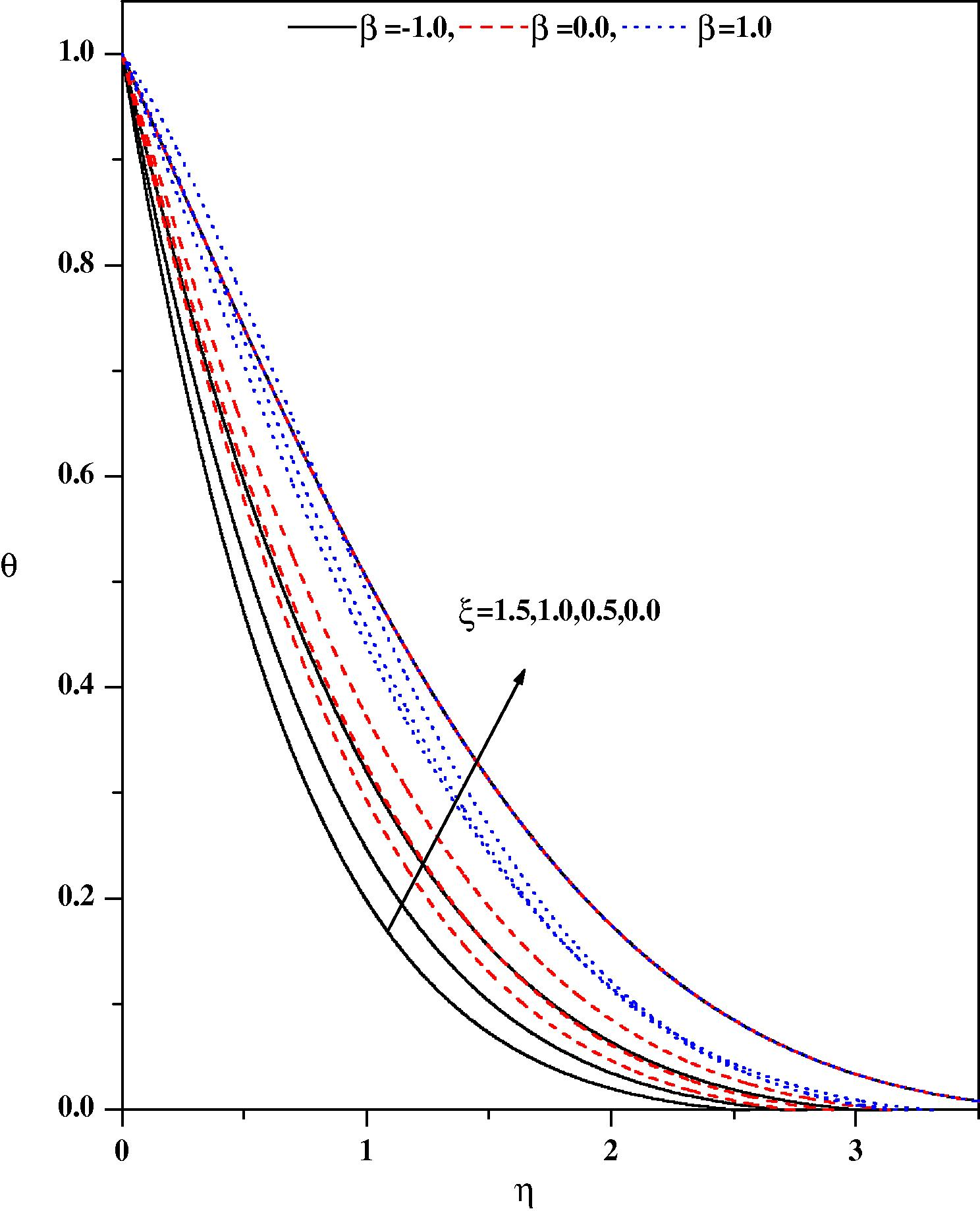
Temperature profiles for different values of β and ξ with Nr = 0.5, fw = 0.5, ε = 0.1, Pr = 1.0, m = 0.333, Ec = 0.1, λ = 0.1.
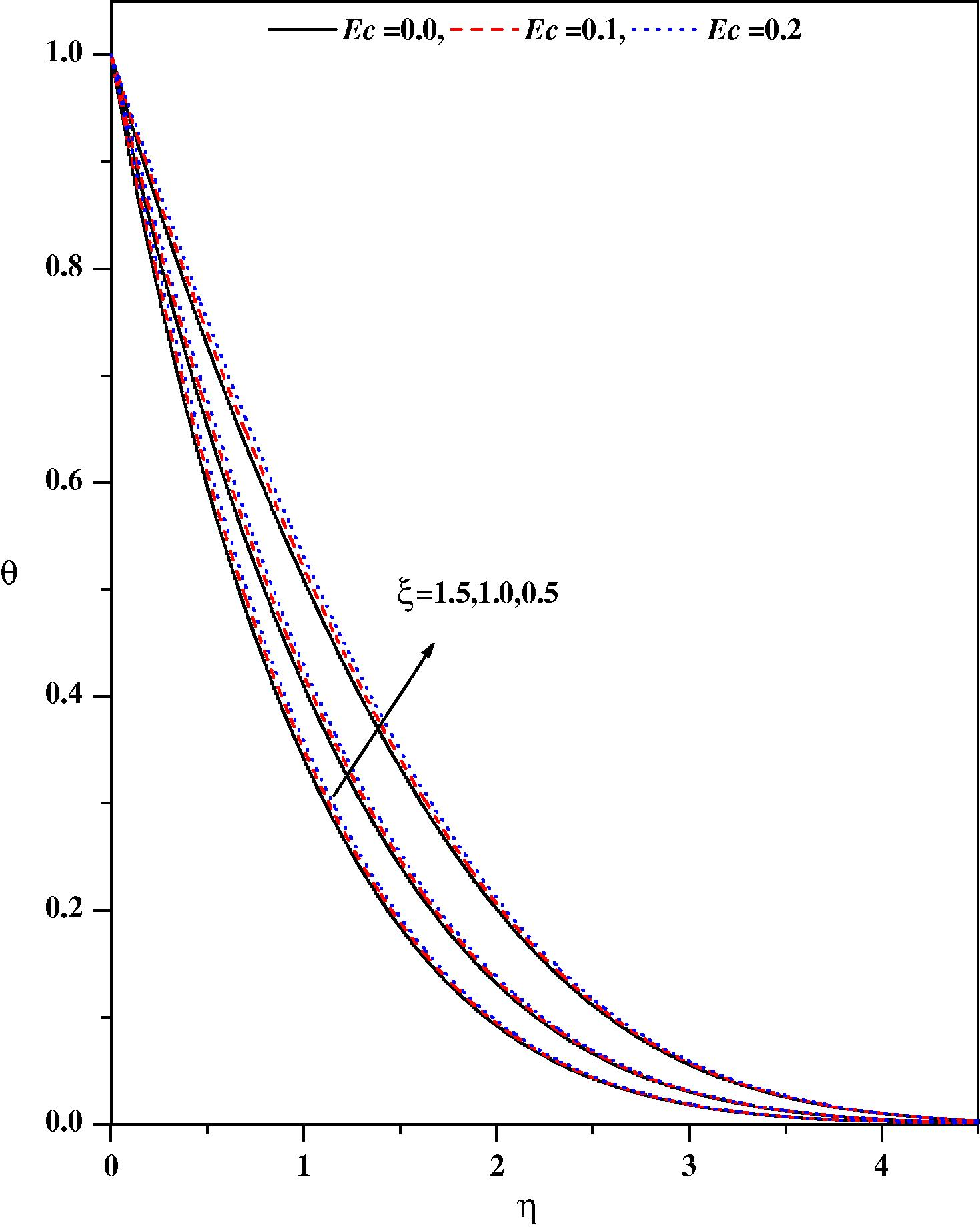
Temperature profiles for different values of Ec and ξ with Nr = 0.5, fw = 0.5, ε = 0.1, Pr = 1.0, m = 0.333, β = 0.1, λ = 0.1.
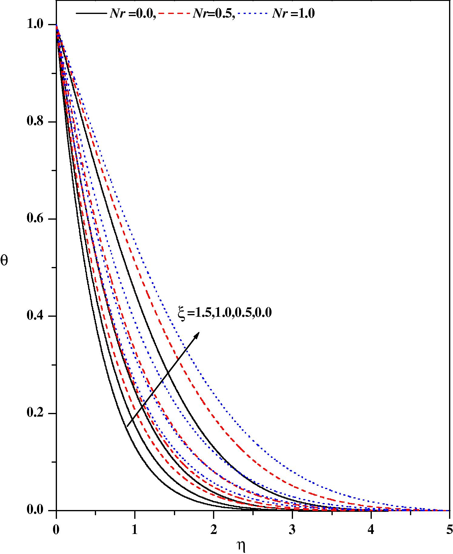
Temperature profiles for different values of Nr and ξ with ε = 0.1, fw = 0.5, Ec = 0.01, Ec = 0.01, m = 0.333, β = 0.1, λ = 0.1.
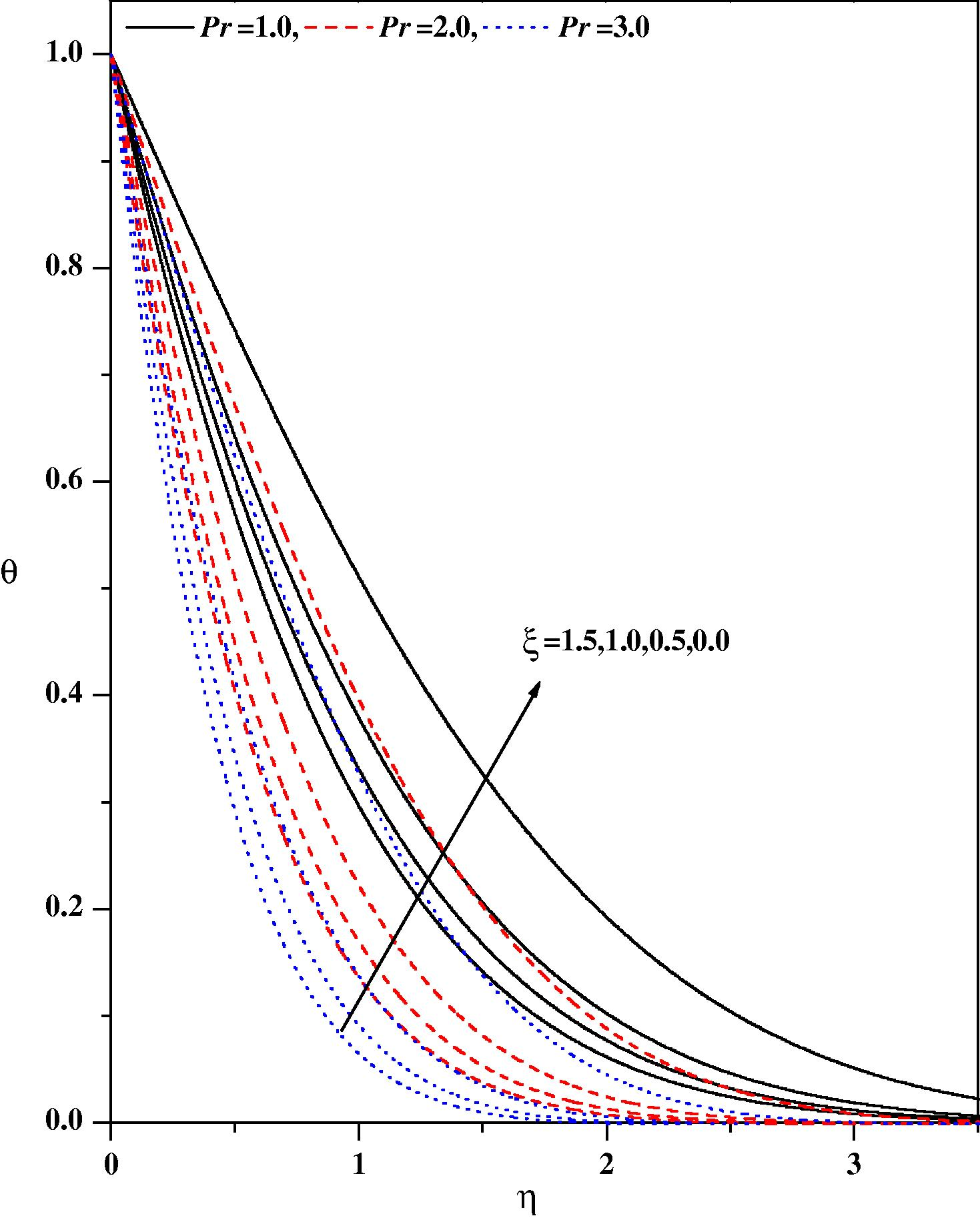
Temperature profiles for different values of Pr and ξ with Nr = 0.5, fw = 0.5, ε = 0.1, Ec = 0.01, m = 0.333, β = 0.1, λ = 0.1.
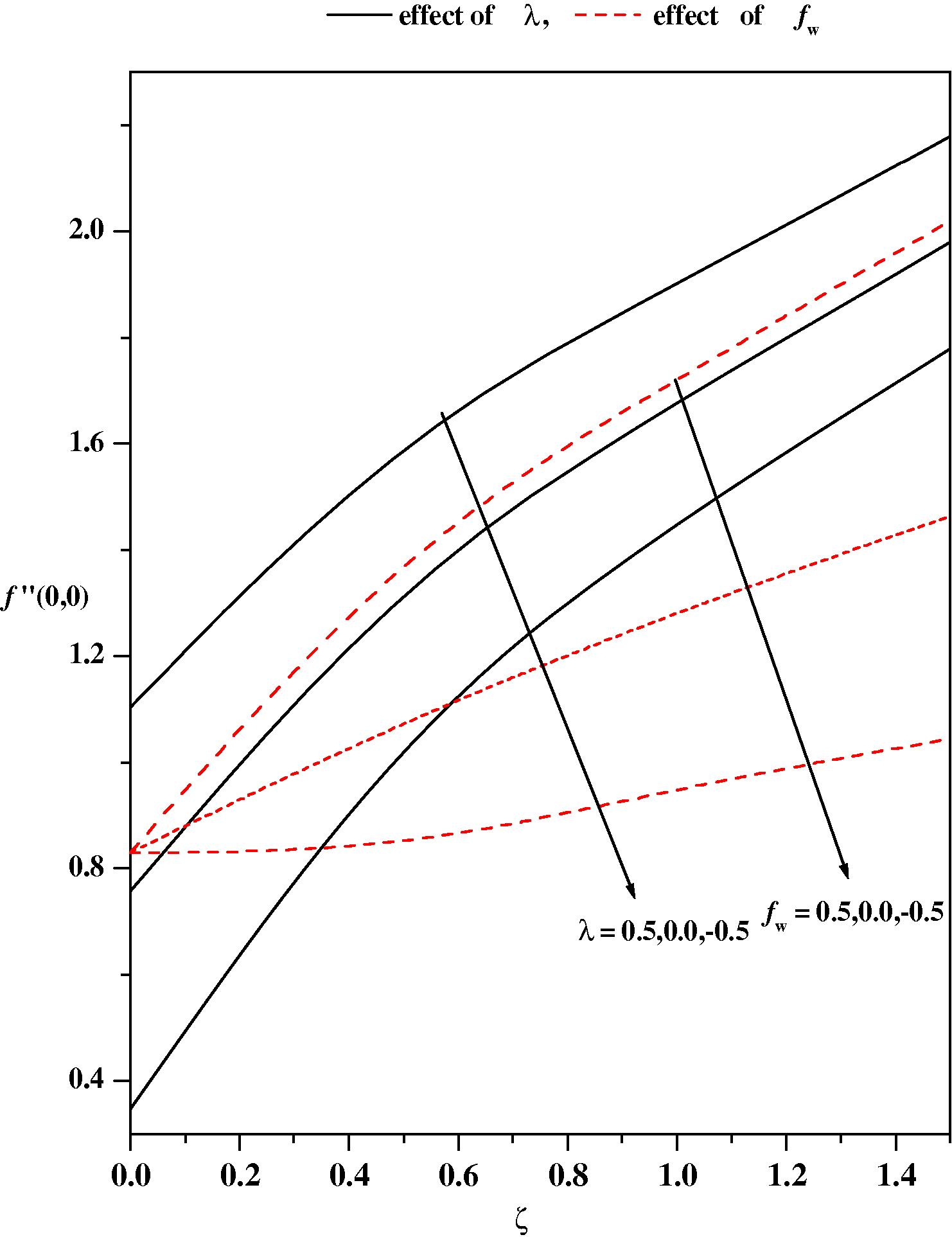
Skin friction f″(0,0) vs. ζ for different values of λ and fw.
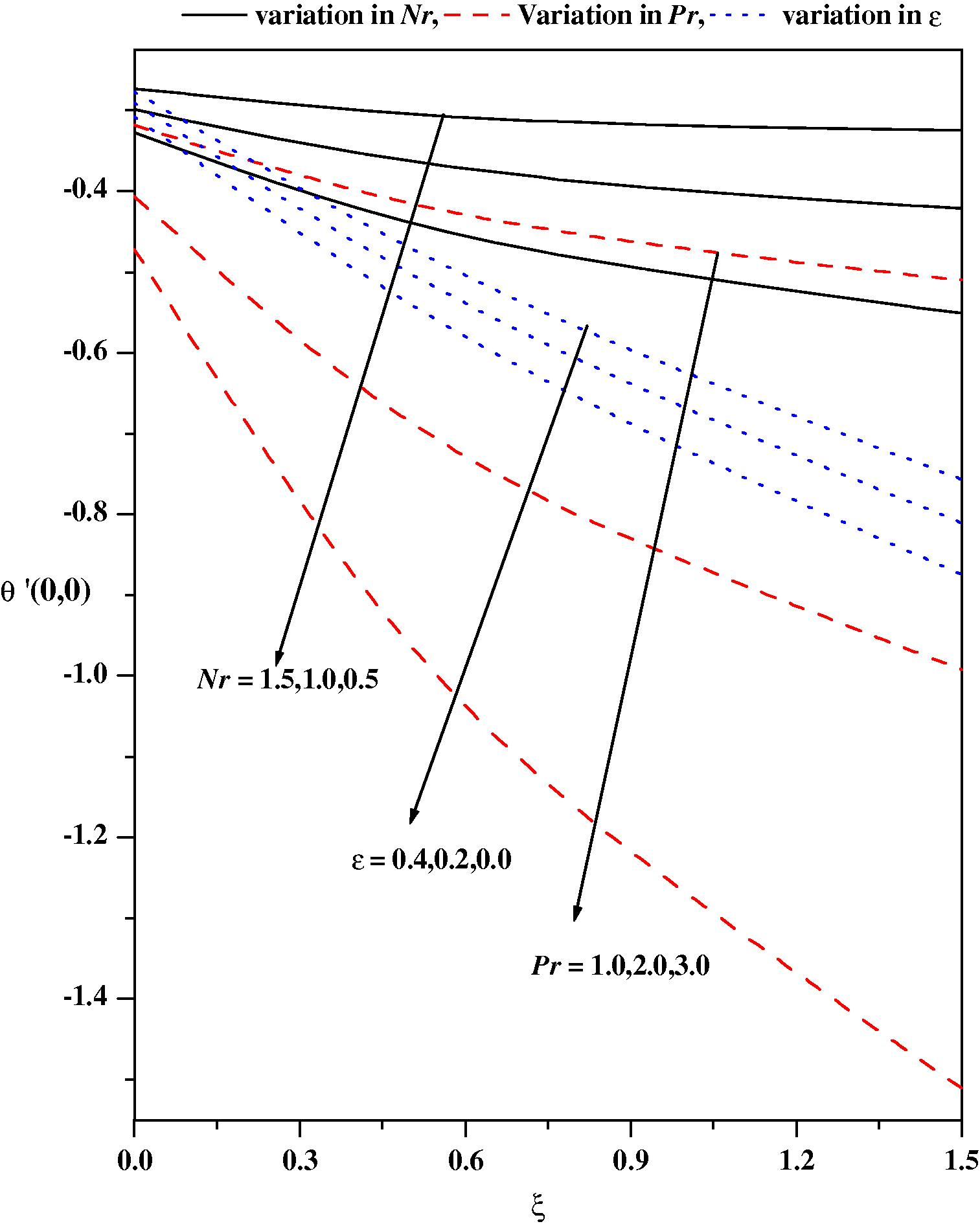
Wall temperature gradient θ′(0,0) vs. ξ for different values of Nr, Pr and ε.
Nr
ɛ
Pr
Ec
fw
m
λ
ξ = 0.0
ξ = 0.5
ξ = 1.0
ξ = 1.5
0.5
0.1
−1.0
1.0
0.1
0.5
0.333
−0.5
0.5244012
1.1871145
1.5484974
1.8652896
0.0
0.7571389
1.3590680
1.6787713
1.9794817
0.5
0.9682134
1.5288637
1.8098274
2.0938566
0.2
0.1
−0.5
1.0
0.0
0.5
0.333
0.1
0.7993567
1.3930539
1.7054529
2.0030243
1.0
1.2584687
1.6472000
1.8966861
2.1075742
0.5
0.1
−1.0
1.0
0.1
−0.5
0.333
0.1
0.8008918
0.7819469
0.9331067
1.0274590
0.0
0.8008918
1.0579530
1.2655948
1.4461085
0.5
0.8008918
1.3931195
1.7049015
2.0023298
Nr
ɛ
Pr
Ec
fw
m
λ
ξ = 0.0
ξ = 0.5
ξ = 1.0
ξ = 1.5
1.0
0.1
−0.5
1.0
0.1
0.5
0.333
−0.5
−0.2769064
−0.48430869
−0.64858717
−0.78895611
0.0
−0.2910083
−0.47778577
−0.64210945
−0.78296512
0.5
−0.3005078
−0.47159243
−0.63560712
−0.77671635
1.0
0.1
−0.5
1.0
0.1
0.5
0.0
0.1
−0.1725166
−0.21111232
−0.41617125
−0.60140407
0.333
−0.2932055
−0.47653311
−0.64081323
−0.78173470
1.0
−0.5565393
−0.78539824
−0.85341299
−0.98960036
0.5
0.1
−0.5
1.0
0.1
−0.5
0.333
0.1
−0.3236902
−0.20794937
−0.29920900
−0.35990244
0.0
−0.3236902
−0.35920355
−0.48724070
−0.59055054
0.5
−0.3236902
−0.56201142
−0.76259756
−0.93418515
0.5
0.1
0.2
1.0
0.0
0.5
0.333
0.1
−0.3117204
−0.61486977
−0.82890773
−1.0129173
0.1
−0.3236902
−0.56201142
−0.73000848
−0.93418515
0.2
−0.3357611
−0.50909376
−0.69624943
−0.85542172
0.5
0.1
0.2
1.0
0.01
0.5
0.333
0.1
−0.3236960
−0.56200647
−0.76259184
−0.93418515
2.0
−0.4214001
−0.89351082
−1.2352148
−1.5255585
3.0
−0.4880211
−1.1992261
−1.6753783
−2.0771673
0.5
0.1
−0.5
1.0
0.1
0.5
0.333
0.1
−0.3236951
−0.56201142
−0.76259756
−0.93418515
0.0
−0.3236951
−0.42021284
−0.51066387
−0.58872575
0.5
−0.3236951
−0.25678539
−0.18132886
−0.089466
0.5
0.0
−1.0
1.0
0.1
0.5
0.333
0.1
−0.3369952
−0.59147191
−0.80304921
−0.98427737
0.2
−0.3119196
−0.53593725
−0.72678328
−0.88984710
0.4
−0.2917960
−0.49181601
−0.66615480
−0.81481564
0.0
0.1
−1.0
1.0
0.1
0.5
0.333
0.1
−0.3711618
−0.71473402
−0.98029852
−1.2065980
0.5
−0.3236903
−0.56201142
−0.76259756
−0.93418515
1.0
−0.2933673
−0.47676486
−0.64098734
−0.78186834
2.0
−0.2580753
−0.38481852
−0.50761569
−0.61371660
Before we make a discussion of the results, it is important to summarize the following facts of the flow:
-
The flow direction is parallel to the axis of the wedge.
-
The flow is symmetric about the axis and hence we investigate only in the upper half.
-
The flow is on the inclined plane and there is a difference in temperature between that of the wedge and its surroundings.
-
Since, there is an appreciable temperature difference (Tw − T∞), the effects of free convective are important.
-
The flow is also being affected due to a pressure gradient.
-
In view of (iv) and (v), it is apparent that the flow under consideration is a mixed convective flow.
Figs. 2(a) and 2(b), respectively illustrate the effects of the pressure gradient parameter m and the magnetic parameter ξ on the wall-normal velocity profiles for zero and non-zero values of the other pertinent parameters. It is noticed from Fig. 2(a) that the velocity profiles decrease with increasing values of the pressure gradient parameter m and magnetic parameter ξ in the boundary layer. The effect of increasing values of the pressure gradient parameter m is to reduce the normal velocity and thereby reduce the boundary layer thickness i.e. the thickness is much large for negative values of pressure gradient parameter m than that of zero or positive values of m as clearly seen in Fig. 2(a). This observation holds for all values of the magnetic parameter ξ. It is observed that the normal velocity profile decreases with an increase in the magnetic parameter: this is due to the fact that the introduction of transverse magnetic field, normal to the flow direction, has a tendency to create a drag force, known as the Lorentz force which tends to resist the flow. This behavior is seen even in the presence of other parameters as shown in Fig. 2(b). The effect of the magnetic parameter on the wall-normal velocity profile for both mixed convection parameter λ and suction/injection parameter is shown in Figs. 3(a) and 3(b), respectively. The effect of increasing values of the mixed convection parameter is to reduce the velocity profile. Physically λ > 0 means heating of the fluid or cooling of the wedge surface, λ < 0 means cooling of the fluid or heating of the wedge surface, and λ = 0 means the absence of free convection currents. From Fig. 3(a), we noticed that an increase in λ leads to a decrease in the wall-normal velocity. Also, an increase in the value λ leads to an increase in the temperature difference (Tw − T∞). This leads to reduce the velocity profile due to the enhanced convection and thus decreases the velocity boundary layer thickness. The effect of suction/injection parameter on the normal velocity profile for different values of ξ is shown in Fig. 3(b). It can be seen that the suction (fw > 0) reduces the velocity boundary layer thickness whereas the blowing (fw < 0) has the opposite effect on the velocity boundary layer. These results are consistent with the physical situation. In Figs. 4–11 the numerical results for the temperature profile for several sets of values of the governing parameters are presented. Fig. 4 illustrates the effect of the pressure gradient parameter m and the magnetic parameter ξ on the temperature distribution. The effect of increasing values of the pressure gradient parameter β is to decrease the temperature. This is true even for different values of magnetic parameter. The effect of increasing values of the magnetic parameter ξ is to reduce the temperature. Of course, as explained above, the transverse magnetic field gives rise to a resistive force known as the Lorentz force. This force makes the fluid experience a resistance by increasing the friction between its layers and thus decreases its temperature. Fig. 5 depicts the effects of the suction parameter on the temperature distribution. The thermal boundary layer becomes thicker for suction and thinner for blowing. Fig. 6 depicts the temperature profiles for different values of λ. Increasing the values of λ results in a decrease in the thermal boundary layer thickness and an increase in the magnitude of the wall-temperature gradient, and hence produces an increase in the surface heat transfer rate. The effect of variable thermal conductivity parameter ɛ on the temperature distribution is shown in Fig. 7. The effect of variable thermal conductivity parameter ɛ is to enhance the temperature and this behavior holds for all values of the magnetic parameter. This is due to the fact that the presence of temperature-dependent thermal conductivity results in a reduction in the magnitude of the transverse velocity by a quantity ∂k(T)/∂y and this can be seen from energy equation.
In Fig. 8 the temperature distribution for different values of the heat source parameter are drawn. The direction of heat flow depends both on temperature difference (Tw − T∞) and the temperature gradient. We observe that the temperature distribution is lower throughout the boundary layer for negative values of (heat sink) and higher for positive values of (heat source) as compared with the temperature distribution in the absence of heat source/sink parameter. Physically β > 0; implies Tw − T∞ i.e. the supply of heat to the flow region from the surface. Physically these correspond, respectively, to recombination and dissociation within the boundary layer. Similarly, β > 0 implies Tw − T∞ i.e. the transfer of heat is from flow to the surface: this corresponds to combustion and an endothermic chemical reaction. The effect of increasing the value of heat source/sink parameter is to increase the temperature profile for zero and non-zero values of magnetic parameter. The variations in the temperature profiles for various values of the Eckert number Ec are displayed in Fig. 9. The effect of increasing values of Ec is to increase the temperature profile. This is in conformity with the fact that energy is stored in the fluid region due to frictional heating as a consequence of dissipation due to viscosity, and hence temperature increases as Ec increases. Fig. 10 shows the effect of thermal radiation Nr on temperature profiles in the boundary layer. It is observed that an increase in thermal radiation parameter produces a significant increase in the thickness of the thermal boundary layer of the fluid, and as a consequence the temperature profiles increase. The temperature gradient at the surface increases as the thermal radiation parameter increases which can be observed in Table 4. Fig. 11 exhibits the temperature distribution for different values of the Prandtl number. The figure demonstrates that an increase in the Prandtl number Pr is to decrease the temperature distribution. That is, the thermal boundary layer thickness decreases as Pr increases.
Numerical results for the skin friction coefficient and the Nusselt number θ′(0,0) as a function of f_w and λ for a wide range of magnetic parameter ξ are shown in Figs. 12 and 13, respectively. Fig. 12 shows that for different values of λ, the values of (0,0), are positive and increase as the parameters increase namely, the mixed convection parameter, the suction/injection parameter and the magnetic parameter. An inspection of Figs. 3(a) and 5 reveals that the wall slope of the velocity and temperature profiles increase and decrease, respectively as f_w increases. Hence, by Eq. (14), this results in an increase of the values of both local skin friction coefficient and the local Nusselt number as evidenced in Fig. 12. From Fig. 13, it is noticed that the effect of the variable thermal conductivity parameter and thermal radiation parameter is to increase the wall-temperature gradient, whereas the reverse is true with the Prandtl number and the Eckert number. Increases in the values of Nr have the tendency to increase the conduction effect and to increase the thermal boundary layer. This, in turn, causes the temperature to increase at every point away from the wedge surface. The effects of all the physical parameters on the local skin friction and the local Nusselt number θ′(0,0) are analyzed in Tables 3 and 4. It is observed that the local skin friction coefficient and the local Nusselt number monotonically increase as the pressure gradient parameter increases. Increasing the magnetic parameter also increases the local skin friction coefficient and the local Nusselt number. It is of interest to note that the local Nusselt number monotonically decreases as the pressure gradient parameter increases. Further, the effect of the heat source/sink parameter or the variable thermal conductivity parameter is to enhance the wall-temperature gradient. Further the local Nusselt number is enhanced with increasing Prandtl number.
5 Concluding remarks
Based on the numerical results, some of the interesting results are as follows:
-
The effect of suction is to reduce the thermal boundary layer thickness. This holds for all values of the magnetic parameter, the variable thermal conductivity parameter and the Eckert number.
-
The effect of increasing values of the mixed convection parameter is to increase the momentum boundary layer thickness as well as the thermal boundary layer thickness.
-
The effect of Prandtl number is to decrease the thermal boundary layer thickness and the wall-temperature gradient.
-
The effects of the variable thermal conductivity parameter, the thermal radiation parameter, the Eckert number and the heat source/sink parameter are to enhance the temperature field.
-
Of all the parameters, the mixed convection parameter has the strong effect on the drag, heat transfer rate, the wall-normal velocity and the temperature field of the MHD flow over a permeable non-isothermal wedge.
Acknowledgements
The authors appreciate the constructive comments of the reviewers which led to definite improvement in the paper. One of the authors (KVP) is thankful to the University Grants Commission, New Delhi for supporting financially under a Major Research Project (Grant No. F. No. 41-790/2012 (SR)).
References
- Laminar mixed convection from a continuously moving vertical surface with suction/injection. Heat Mass Transfer. 1998;33:301-306.
- [Google Scholar]
- Thermal stratification effects on non-linear MHD laminar boundary-layer flow over a wedge with suction or injection. Int. Commun. Heat Mass Transfer. 2003;30:717-725.
- [Google Scholar]
- Radiation effect on MHD mixed convection flow about a permeable vertical plate. Heat Mass Transfer. 2008;45:239-246.
- [Google Scholar]
- Physical and Computational Aspects of Convective Heat Transfer. In: 1st ed.. NewYork: Springer-Verlag; 1984. p. 385
- [Google Scholar]
- Thermal radiation effects on MHD forced convection flow adjacent to a non-isothermal wedge in the presence of a heat source/sink. Heat Mass Transfer. 2003;39:305-312.
- [Google Scholar]
- Thermodynamical modeling of viscous dissipation in magneto hydrodynamic, flow. Theor. Appl. Mech.. 2007;34:197-219.
- [Google Scholar]
- Forced convection over a continuous sheet with suction or injection moving in a flowing fluid. Acta Mech.. 1999;138:1-11.
- [Google Scholar]
- Buoyancy effects in boundary layer adjacent to a continuous moving horizontal flat plate. ASME J. Heat Transfer. 1980;102:170-172.
- [Google Scholar]
- Heat transfer with variable thermal conductivity in a stagnation point flow towards a stretching sheet. Int. Commun. Heat Mass Transfer. 1996;23:239-248.
- [Google Scholar]
- MHD visco-elastic fluid flow over a non-isothermal stretching sheet. Int. J. Eng. Sci.. 2004;42:935-946.
- [Google Scholar]
- Mixed convection flow over a vertical wedge embedded in highly porous medium. Heat Mass Transfer. 2001;37:139-146.
- [Google Scholar]
- Thermophoresis effects on non-Darcy MHD mixed convective heat and mass transfer past a porous wedge in the presence of suction/injection. Theor. Appl. Mech.. 2010;37:203-227.
- [Google Scholar]
- Buoyancy effects in boundary layers on inclined continuous moving sheets. ASME J. Heat Transfer. 1980;102:371-373.
- [Google Scholar]
- Influence of temperature-dependent viscosity and thermal radiation on MHD forced convection over a non-isothermal wedge. Appl. Math. Comput.. 2009;212:194-208.
- [Google Scholar]
- Mixed convection flow over a vertical power law stretching sheet. Int. J. Numer. Meth Heat Fluid Flow. 2009;20:445-458.
- [Google Scholar]
- Momentum and heat transfer in visco-elastic fluid flow in a porous medium over a non-isothermal stretching sheet. Int. J. Numer. Meth. Heat Fluid Flow. 2000;10:786-802.
- [Google Scholar]
- The effects of variable fluid properties on the hydromagnetic flow and heat transfer over a non-linearly stretching sheet. Int. J. Ther. Sci.. 2010;49:603-610.
- [Google Scholar]
- Non-Darcian flow and heat transfer along a permeable vertical surface with nonlinear density temperature variation. Acta Mech.. 2011;220:139-154.
- [Google Scholar]
- Radiation and free convection flow through a porous medium. Int. Commun. Heat Mass Transfer. 1998;25:289-295.
- [Google Scholar]
- Buoyancy force and thermal radiation effects in MHD boundary layer visco-elastic fluid flow over continuously moving stretching surface. Int. J. Therm. Sci.. 2005;44:465-476.
- [Google Scholar]
- Convection heat transfer at a stretching sheet with suction or blowing. J. Math. Anal. Appl.. 1994;188:1002-1011.
- [Google Scholar]
- Hydromagnetic convection at a cone and a wedge. Int. Commun. Heat Mass Transfer. 1992;19:701-710.
- [Google Scholar]
- Magneto hydrodynamic stability of boundary layers along a flat plate in the presence of transverse magnetic field. ZAMM. 1978;58:555-560.
- [Google Scholar]
- Magneto hydrodynamic stability of boundary layers along a flat plate with pressure gradient. Acta Mech.. 1986;65:41-50.
- [Google Scholar]
- Thermal boundary layers in magneto hydrodynamic flow over a flat plate in the presence of a transverse magnetic field. Acta Mech.. 1994;105:233-238.
- [Google Scholar]
- Uniform suction/blowing effect on forced convection about a wedge: uniform heat flux. Acta Mech.. 1998;128:173-181.
- [Google Scholar]
- MHD forced convection flow adjacent to a non-isothermal wedge. Int. Commun. Heat Mass Transfer. 1999;26:819-827.
- [Google Scholar]


