Translate this page into:
The application of the numeral method of lines on carbon dioxide captures process: Modelling and simulation
⁎Corresponding author at: 4311 Kliptown Golf Course, Union road, Pimville, Soweto 1809, South Africa. 211121670@tut4life.ac.za (Makhanana Innocent Nkhwashu)
-
Received: ,
Accepted: ,
This article was originally published by Elsevier and was migrated to Scientific Scholar after the change of Publisher.
Peer review under responsibility of King Saud University.
Abstract
CCP is the process of capturing and storing CO2 away from the atmosphere. Out of the three available methods of capturing CO2, this study focused on Post-combustion process. The Mass balance equations of the flue gas was modelled as a PDE and then reduced to an ODE by the application of Numerical Method of Lines. The equation was discretized to 0.8 m. Mono-ethanolamine, Potassium Carbonate and Chilled Ammonia were studied to investigate their absorption capacity to capture CO2. Two specific mass transfer area correlations were used in order to validate the results. The results followed the same trends with minimal error of less than 21%. Discretization of 1 m was done for the absorbent which captured the highest amount of CO2 in order to further validate the results. The results corresponded well with each other. MEA has proven to be the best absorbent in capturing Carbon dioxide than the other two absorbents.
Keywords
Carbon dioxide capture process
Post-combustion process
Modelling
Simulation
Numerical method of lines
Nomenclature
-
mass (kg)
-
mass flow rate (kg/s)
- ρ
-
density (kg/m3)
- V
-
Volume (m3)
- F
-
Volume flow rate (m3/s)
- U
-
Velocity (m/s)
- Z
-
Column height (m)
- n
-
number of moles (moles)
-
molar flow rate (moles/s)
- Mr
-
molar weight (kg/kmol)
- A
-
is the surface area (m2)
- v
-
volume of the column (m3)
- Ni
-
the molar flux (kmol/m2.s)
-
mass transfer area (m2/m3)
- Ki
-
mass transfer coefficient
- Ci, Civ,int
-
concentration of component i (kmol/m3)
- DAB
-
molecular diffusivity (m2/s)
- εm
-
mass Eddy diffusivity (m2/s)
-
Reynolds number for the liquid phase
-
specific packing area (m2/m3)
1 Introduction
The Numerical Method of Lines (NMOL) is regarded as a special finite difference method but more effective with respect to accuracy and computational time than the regular finite difference method (Sadiku, 2000). It is basically the discretization of independent variables except for one on a partial differential equation (Alabdali and Bakodah, 2014). It is a general way of perceiving PDEs as ODEs (Ordinary differential equation). Our physical world is most generally described in scientific and engineering terms with respect to three-dimensional space and time which we abbreviate as space-time. PDEs provide a mathematical description of physical space-time, and they are therefore among the most widely used forms of mathematics (Hamdi et al., 2009). Application of Numerical method of lines is applied on Carbon dioxide capture process (CCP) which is the process of capturing and storing carbon dioxide away from the atmosphere. Carbon dioxide is removed after or before combustion of flue gas (Kothandaraman, 2010). There are three main processes of capturing carbon dioxide. Carbon dioxide can be captured by post combustion process, oxy-fuel combustion and pre- combustion process. Post-combustion capture process is the most preferred process out of the three (Kothandaraman, 2010). It is the most potentially, technically and economically mature carbon dioxide capture technology used to capture CO2 from the flue gases produced by the power generation sector (Gáspár and Cormos, 2012). The current state-of-the-art technology for the post combustion capture process is the chemical absorption. It involves carbon dioxide being diffused into the solvent absorbent. Post-combustion technologies available for CO2 removal include membranes, adsorption, chemical absorption, physical absorption and cryogenic processes. Some of these technologies are well established and are being used commercially, while some are being improved or need additional improvements for feasibility (Devries, 2014). In post combustion process, Fossil Fuel is burned with air to produce a flue gas containing water (H2O), Oxygen (O2), Nitrogen (N2), Nitrogen oxide (NO2), Sulfur dioxide (SO2) and Carbon dioxide (CO2). The flue gas produced is then cooled down and fed into an absorption column where a solvent absorbent is fed at the top of the column (Mohammad et al., 2013). In recent years, there has been increasing demand for a significant reduction of carbon dioxide emissions from industrial sources to decrease the global warming problem (Khan et al., 2011). I South Africa, thereis no legislation Monoethanolamine (MEA) is one of the popular amines used in carbon dioxide capture process (Fernandez, 2013). Other absorbents have lately surfaced and are the focus areas since they are developing. These absorbents include chilled ammonia, Di-ethanolamine (DEA), N-methyl-di-ethanolamine (MDEA), 2-amino-2-methyl-1-propanol (AMP) and potassium carbonate (K2CO3) and pure water. The most mature and commercially applied amine is Monoethanolamine (MEA) due to its high absorptive capacity. Effective methods have to be put in place to ensure that the emission of Carbon dioxide is reduced. This will have to happen by understanding the performance of the process. This process covers the mass transfer of carbon dioxide from the bulk gas to the solvent absorbent solution. An important characteristic of reactive absorption process is the variation of reaction velocities, from very low to high instantaneous reactions (Peng et al., 2002). Following the numerical analysis of the Carbon dioxide capture process, the flue gas volume flow was regarded as an influential element. Volume flow equation was developed in a form of a 2D model for the flue gas volume. A mathematical technique, NMOL was applied to the developed flue gas volume flow PDE. The approach yielded a better understanding on the performance of the process when focusing on the volume flow. For better understanding, three absorbents MEA, K2CO3 and Chilled ammonia were investigated, and the most efficient absorbent was identified when focusing on the behaviour of the flue gas volume flow only. The equations were validated by simulating Python computer coding software. The output was compared to the previous studies done on NMOL. The model better explains the behaviour of the flue gas volume flow rate. Its purpose is to mimic the carbon dioxide flue gas volume flow. So many models that are based on the concentration and temperature distribution of the flue gas and solvent absorbent have been studied. There is still a need for volume flow distribution of the flue gas.
2 Modelling
2.1 Modelling assumptions
Fig. 1 shows the schematic diagram of the absorption column. The flue gas obtained from the combustion of coal enters at the bottom of the column and the solvent absorbent coming from the recycle stream enters from the top of the column. The Carbon dioxide free flue gas exit from the top of the column and the Carbon dioxide rich solvent exit from the bottom of the column.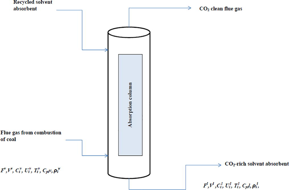
Schematic diagram of the absorption column.
The volume flow equations of the liquid and gas phase are modelled by applying conservation of mass. The following assumptions have been made:
-
Density and viscosity of the liquid and gas are assumed to be constant.
-
The flow equations will be modelled at constant column temperature of the flue gas but it can be manipulated to suit the process.
-
The flow rate changes with column height at various process times.
-
Constant velocity is assumed.
-
Evaporation of solvents is negligible since the focus is on the flue gas volume flow.
2.2 Mathematical models description
2.2.1 Mass balance equation
Below is the steady state mass balance equation.
The change in volume across the column is given by:
U is the velocity and Z is the column height. In order for the absorption to occur, mass transfer and chemical reaction should occur. The following equations are necessary to satisfy the mass transfer process written as follows:
Where A is the surface area of the column and is given as follows:
v is the volume of the column. Ni is the molar flux and is the mass transfer area. The volume of the column can be expressed by:
Eq. (10) is substituted into Eqs. (7) and (11) is formed,
Eq. (11) is substituted into Eq. (5):
Eq. 12 is a partial differential equation for the Flue gas flow rate.
2.2.2 Mass transfer equation
The molar flux Ni is modelled according to the two film theory. The molar flux across the mass transfer area is expressed by the following equation:
DAB is the molecular diffusivity, εm is the mass Eddy diffusivity. The molecular diffusivity for a gas-liquid system is expressed by (Geankoplis, 1993):
Ap is an association parameter, Va is the Carbon dioxide molar volume. T is the temperature of the solvent.
Eq. (13) becomes;
2.2.3 Mass transfer area correlation
The mass transfer area developed by De Brito et al. has been used for this research. The correlation was used in a study by (Gáspár and Cormos, 2012) on Dynamic modelling and absorption capacity assessment of CO2 capture process. The liquid-phase analysis was assumed to be more trustworthy and was exclusively used. Gas-side resistance was neglected in the calculations. An empirical relation was developed from the results (Tsai, 2010).
The derived PDE represent the dynamic behaviour of the flue gas volume flow. Eq. (21) is the developed partial differential equation for the volume flow of the flue gas.
2.2.4 Application of NMOL to the derived PDE model
The numerical method of lines (NMOL) was used to solve the PDE of the volume flow rate. The column height of 4 m was discretized to 0.8 m segments. This was to minimize error in the results. Discretization of dynamic partial differential equations in Carbon dioxide capture process has not been studied. NMOL is another way of perceiving the PDE as an ODE because one dependent variable is kept constant and the other one dependent. Volume profiling was done at each segment of the column to yield the following series of equations with the aid of a Spyder console embedded within the python software.
is the segment length of 0.8 m. When the NMOL is applied on Eqs. (19) and (20) is formed. The column will have 5 segments with a length of 0.8 m. t = (0,100).
Segment 1 where Z = 0–0.8 m
Segment 2 where Z = 0.8–1.6 m
Segment 2 where Z = 1.6–2.4 m
Segment 2 where Z = 2.4–3.2 m
Segment 2 where Z = 3.2–4 m
2.2.5 Validation of the model
The model was validated by applying another mass transfer correlation by Dragan. De Brito and Dragan’s correlation for effective mass transfer area is similar because they are both Reynolds number dependant equations (Tsai, 2010). The specific packing area is replaced by segment area since the NMOL is applied and it the difference between the authors equations. Eq. (28) below denotes Dragan (Geankoplis, 1993).
The results were validated by discretizing the column height to 1 m segments for the system that performed better.
2.2.6 Simulation
Python computer coded software was used to simulate the modelled equation. Python is one of the most popular programming languages for scientists and engineers. Python is widely used in industrial scientific computing (Dolgopolovas, 2014) hence it was selected as the simulator for the study. Spyder was used as the editor. The flue gas composition is listed in Table 1. It contains 8.4% of the undesired Carbon dioxide. Three absorbents MEA, Potassium Carbonate and Chilled ammonia systems were simulated in order to see how they behave when capturing Carbon dioxide from flue gas. Only the gas phase was modelled and simulated.
Gas constituent (vol%)
Flue gas
Mw (kmol/kg)
Density (kg/m3)
Nitrogen%
74.13
28.03
1.251
Carbon dioxide%
8.40
44.01
1.98
Water vapour%
4.52
18
1.27
Oxygen%
12.04
32
1.429
Argon%
0.91
39.95
1.784
The design assumption was based on parameters listed in Table 2. The flue gas composition is after the treatment of other unwanted gases. The parameters were manipulated to best suit the desired results. The pressure is close to Standard Temperature and Pressure (STP).
Flue gas stream
Value
Units
Feed volume
1000
m3
Temperature
50
°C
Pressure
1.05
Bar
Table 3 below is the column dimensions. The absorption column is the Mellapak structured design.
Parameter
Value
Units
Column height
4
m
Column diameter
0.5
m
3 Results and discussion
3.1 Validation of the model
Accuracy in the application of NMOL is proven when the evaluation of the model parameters applied at different segments results to the same graphical trend. This was proven by the work of (Cutlip and Shacham, 1999) where the NMOL was applied to a temperature related problem using Polymath as the simulator. The graphical solution showed that the results of all the segments follow the same trend. In the work of Schiesser, the NMOL was applied to a diffusion equation which showed agreement to the results of (Cutlip and Shacham, 1999). Bidie and Joubert (2008) presented results with 11 curves with the aim of doing an error analysis on NMOL. This is an indication that NMOL results for each segment will start at the same point and will follow the same trend.
3.2 Results
This study is emphasized on the profiling of the flue gas volume flow rate done at each segment of the column. The NMOL procedure was applied and the profile of the volume flow is shown for each discretized segment of the column. Volume flow tests were conducted using the three absorbents i.e. Chilled ammonia, Mono-ethanolamine and Potassium Carbonate at a run time of 100 s. Fig. 2 designates the simulation results with the application of NMOL. The results show that the application of the NMOL to this study is accordingly, as the expected solution of the same graphical trends is attained.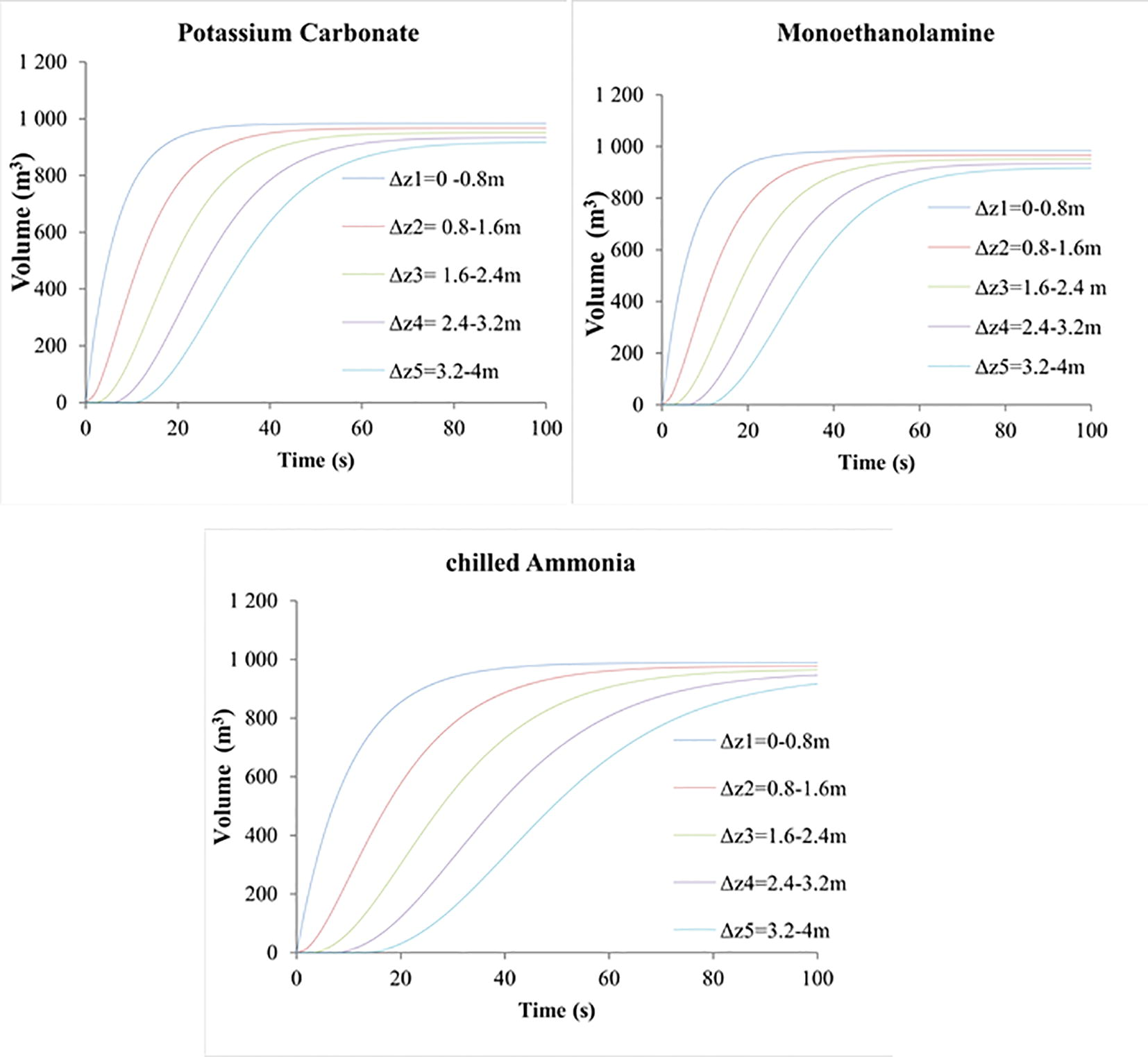
Numerical method of lines results for the volume of the flue gas flowing across the absorption column.
In Fig. 2, the numerical method of lines results for all the three system investigated follow the same trend. The process time is made to be the continuous variable and the column height is made the constant variable. At t = 0, there is nothing in the absorption column hence the volume will be 0 m3. The volume of the flue gas increases as time progresses at each discretised section. The volume of the flue gas stabilised when it reached the peak of the segment. The results in Fig. 2 are used to apply a real life situation which is to determine which absorbent performs better. The volume of the flue gas is affected by each absorbent used since the results of the volume were not the same. The feed volume of the flue gas is 1000 m3.With NMOL results, at t = 0 the there is no flow of gas in the absorption column and the flue gas in the holding is 1000 m3. As shown in Fig. 2, the volume of the flue gas decreases as it flows up the column. The volume decreases for the MEA, Chilled ammonia and Potassium carbonate systems.
In this paper, 8.4% CO2 composition is used to account for the amount of CO2 available in the feed gas. Which means that, out of the feed gas lost during the process by either absorption or through recycling, 8.4% of it will account for the CO2 captured considering that the latter absorbents can only capture CO2 amongst other feed gas constituents because of its acidic nature (Kothandaraman, 2010). To determine the amount of CO2 absorbed/captured in the process, Eq. (27) is used to calculate the fraction of the flue gas lost after absorption.
Eq. (28) is used to calculate the absorption efficiency of the three absorbents. The absorption rate of CO2 is compared in Fig. 3 for the three absorbents ‘system. MEA showed the highest absorption rate compared to Chilled ammonia and potassium Carbonate.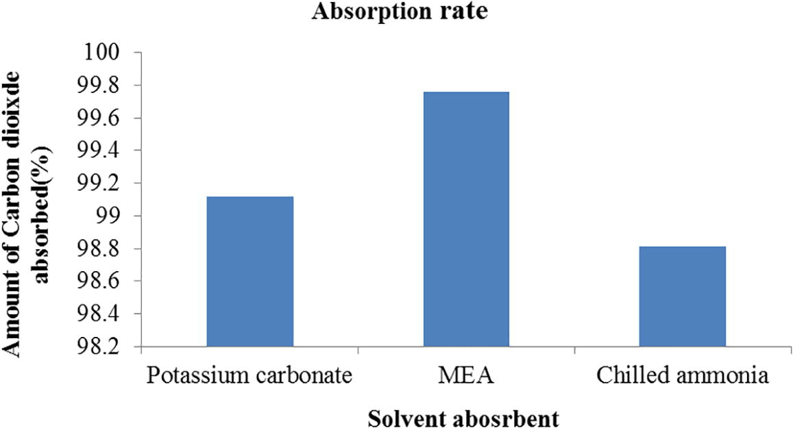
Absorption rate of Carbon dioxide for the MEA, Potassium Carbonate and Chilled ammonia system.
3.3 Validation of the results
From the work of (Gáspár and Cormos, 2012) the mass transfer area of De Britos et al. was used. MEA proved to have high absorption efficiency though it was compared with other amines. With this work, MEA is compared with other solvents and it has proved to have high absorption efficiency. In the work of (Tsai, 2010), a review was done for the mass transfer area of De Britos et al. and Dragan et al. Since both are Reynolds’s number dependant, they make a good comparison. The comparison of the volume results of the flue gas for De Britos and Dragan mass transfer area correlation is shown by Fig. 4. The two correlations plots almost lie on the same curve.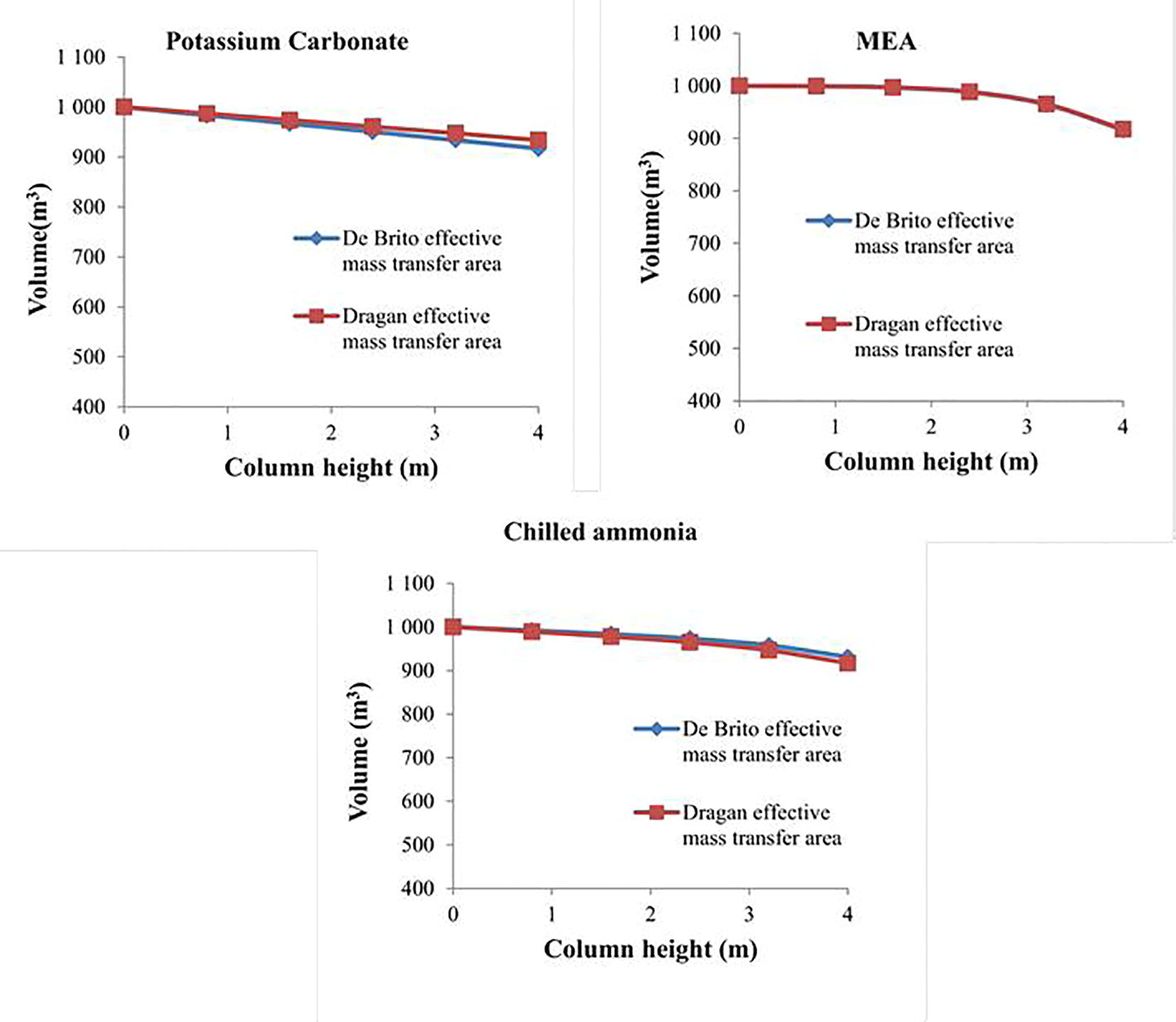
Validation of the model by using two different mass transfer area correlations, the volume of the flue gas at the peak of each segment of the column.
The approximation for the De Britos and Dragans mass transfer correlation validates the certainty of the model and results. The absorption rate of CO2 for the two correlations is compared in Fig. 6. Eqs. (27) and (28) are used to calculate the absorption rate. MEA has the highest absorption rate than Potassium Carbonate and Chilled ammonia on both correlations.
Fig. 5 presents the amount of Carbon dioxide absorbed for Dragan and De Britos mass transfer area correlation. De britos correlation seemed to have yielded the highest amount of Carbon dioxide absorbed with comparison to Dragan’s correlation. An error analysis of the two mass transfer correlations is done. The analysis determines the deviation of the two correlations from each other. The results are listed in Table 4. Eq. (29) is used to calculate the% error difference.
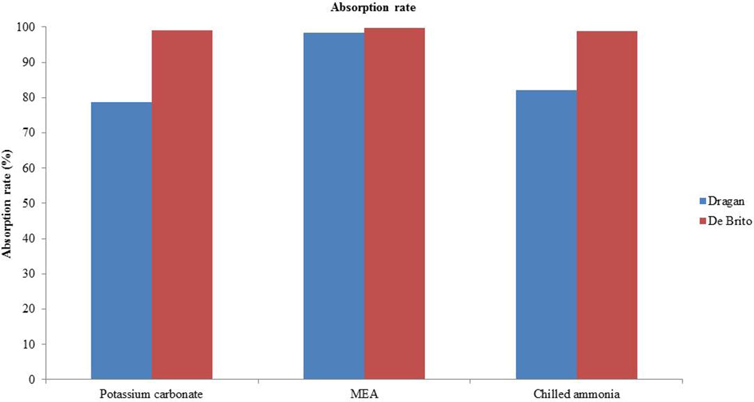
Comparison of the absorption rate for Dragan and De Britos mass transfer area correlation.
Potassium carbonate
MEA
Chilled ammonia
20.54
1.31
16.87
As indicated in Table 4, MEA has 1.31% error difference, which is the lowest compared to Potassium Carbonate and Chilled ammonia% error analysis. MEA has been widely studied compared to the other absorbents. The testing of the mass transfer might have been based on MEA study since it is commercially and industrially matured absorbent in CCP. Potassium Carbonate has produced the highest%error. The results are accepted based on the error analysis. Potassium Carbonate results are 79.46% accurate, Chilled Ammonia results are 83.13% and the MEA results are 98.69% accurate
To validate the NMOL results, another discretization of 1 m segment is done. It is graphically presented in Fig. 6. Cutlip and Shacham (1999) made a validation by discretising using a different value. The results for 0.8 m discretization and 1 m discretization are comparable with a minimal difference. The results are considered valid.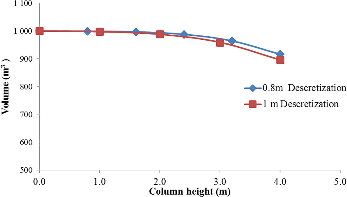
NMOL validation- 0.8 m segmentation and 1 m segmentation: Peak volume of the flue gas at each segment of the column.
4 Conclusion
The simulation was conducted to profile the volume of the flue gas for the post-combustion Carbon dioxide absorption process. A 2D Partial differential equation has proven to be the best solution in profiling the volume of the flue gas. The equation has been validated by using two mass transfer area correlations. An error analysis was conducted and the MEA system’s results produced an error of 1.31%, followed by Chilled Ammonia with an error of 16.87% and Potassium Carbonate with an error of 20.54%. Based on the error analysis the results and the model are valid. The Numerical method lines used to solve the Partial differential equation is being supported by this study. NMOL is a good way of seeing PDEs as ODEs and that has been proven. Time and space are an important factor in the process. By the application of NMOL, it has allowed time and space dimension to play an important role in the equation. As stated that real life situations are in two dimension or more.
Acknowledgements
I would like to thank the Tshwane University of Technology’s Faculty of Engineering and Built Environment, Department of Chemical, Metallurgical and Materials Engineering for their academic support and extending my gratitude to the National Research Foundation (NRF) for funding my studies, Lastly, Dr. Valerie Naidoo of the Water Research Commission (WRC) for the helpful discussions on data analysis.
References
- A new modification of the method of lines for first order hyperbolic PDEs. Appl. Math.. 2014;5:1457-1462.
- [Google Scholar]
- Bidie J.N.M., Joubert S.V., Fay T.H. “Error analysis of the numerical method of limes”. Buffelspoort TIME2008 Peer-reviewed Conference Proceedings, 2008.
- Cormos A.M., Gaspar J., Padurean A., Cormos C.C., Agachi S., Techno-economical analysis of carbon dioxide absorption in mono-ethanolamine by mathematical modelling and simulation, 20th European Symposium on Computer Aided Process Engineering – ESCAPE, 2010, 20, pp. 2-5.
- Problem solving in Chemical engineering with Numerical methods. Upper Saddle River, NJ: Prentice Hall; 1999.
- CO2 Absorption into concentrated carbonate solutions with promoters at elevated temperatures. Urbana, Illinois: University of Illinois Degree of Master of Science in Agricultural and Biological Engineering; 2014.
- “Python for scientific computing education: modeling of queuing systems”. Sci. Programm.. 2014;22:37-51.
- [Google Scholar]
- Novel process designs to improve the efficiency of post-combustion carbon dioxide capture. PhD Chemical Engineering: Netherlands, University of Delft; 2013.
- Dynamic modelling and absorption capacity assessment of CO2 capture process. Int. J. Greenhouse Gas Cont.. 2012;8:45-55.
- [Google Scholar]
- Transport processes and separation principles (3rd Edn). USA, Prentice Hall: University of Minnesota; 1993. p. :426-634.
- Modelling reactive absorption of CO2 in packed columns for post-combustion carbon capture applications. Chem. Eng. Res. Design. 2011;89:1600-1608.
- [Google Scholar]
- Kothandaraman A., “Carbon Dioxide Capture by Chemical Absorption: A Solvent Comparison Study”. Department of chemical engineering, Massachusetts Institute of Technology. Degree of Doctor of Philosophy in Chemical Engineering, 2010, 263.
- Mohammad R.M., Abbas Z., Singh P., Feron P., “Carbon Dioxide Post-Combustion Capture: Solvent Technologies Overview, Status and Future Directions”. Materials and processes for energy: communicating current research and technological developments, 2013, A. Méndez-Vilas, Ed.
- A comparison of steady-state equilibrium and rate-based models for packed reactive distillation columns. Ind EngChem. Res.. 2002;41:2735-2744.
- [Google Scholar]
- A simple introduction to the method of lines. Int. J. Electr. Eng. Educ.. 2000;3(37):282-296.
- [Google Scholar]
- Mass Transfer Area of Structured Packing. Urbana, Illinois: The University of Texas at Austin Partial Fulfillment Doctor of Philosophy; 2010.
- Fundamentals of Momentum, Heat, and Mass Transfer (5th Edn). United States of America: John Wiley & sons Inc.; 2007. p. :398-432.


