Translate this page into:
Two-field-variable meshless method based on moving kriging interpolation for solving simply supported thin plates under various loads
*Corresponding author anirut.lua@kmutt.ac.th (A. Luadsong)
-
Received: ,
Accepted: ,
This article was originally published by Elsevier and was migrated to Scientific Scholar after the change of Publisher.
Available online 16 December 2014
Peer review under responsibility of King Saud University.
Abstract
Meshless method choosing Heaviside step function as a test function for solving simply supported thin plates under various loads is presented in this paper. The shape functions using regular and irregular nodal distribution as well as order of polynomial basis choice are constructed by moving kriging interpolation. Alternatively, two-field-variable local weak forms are used in order to decompose the governing equation, biharmonic equation, into a couple of Poisson equations and then impose straightforward boundary conditions. Selected numerical examples are considered to examine the applicability, the easiness, and the accuracy of the proposed method. Comparing to an exact solution, this robust method gives significantly accurate numerical results, implementing by maximum relative error and root mean square relative error.
Keywords
Biharmonic equation
Meshless method
Moving kriging interpolation
Thin plate bending problems
1 Introduction
The structures of plate are one of the important components in various applications. There are many scientists or researchers who have analyzed these structures. Exact analysis for such plates is usually very difficult, in spite of the existence of analytical solution in some special cases of geometry and loads. Therefore, various numerical methods have been developed. Meshless method has become very attractive and efficient for development of adaptive methods for solving thin plate bending problem. The main advantage of meshless methods is to get rid of or at least alleviate the difficulty of meshing and re-meshing the entire plate structure. For analysis of thin plate bending, it is well known that high order derivatives of field variables in the governing equation give rise to difficulties in solution of boundary value problems because of worse accuracy of numerically evaluated high order derivatives. The order of the differential operator can be decreased mathematically by decomposing this operator into two lower order differential operators with introducing new field variables.
To circumvent the problems associated with meshing, a number of works for plates have been investigated based on meshless methods. Krysl and Belytschko (1995) first employed the element free Galerkin method (EFGM) to analyze the thin plate problems while Liu (2003) introduced the idea of moving kriging interpolation (MK) and show how it can be used to formulate a new type of meshless method in heat conduction problems. Long and Atluri (2002) extended the meshless local Petrov–Galerkin (MLPG) method for solving thin plate bending problems. Li et al. (2005) utilized the kinematics of a three-dimensional solid of the conventional plate assumption, and proposed a lock-free MLPG formulation for plates. Sladek et al. (2002a,b) decomposed the biharmonic differential equation into Poisson equations, and derived the local boundary integral equations (LBIE) for the thin plate bending problems. Leitao (2001) and Bitaraf and Mohammadi (2010) combined the point interpolation technique with the collocation scheme to derive system of governing equations, and proposed the finite point method (FPM). Based on the recursive composite multiple reciprocity method, Fu and Chen (2009) and Fu et al. (2009) employed a boundary-only collocation scheme-boundary particle method (BPM) to simulate the bending problems of the Kirchhoff plate and Winkler plate. All of these meshless methods do not need an element mesh for the interpolation of the field or boundary variables; however, some of them require background cells for numerical integration, which makes these methods being not “truly” meshless method. Recently, Sladek et al. (2013) applied the new field variable for solving thin plate bending problems by meshless method comparing the solution using either the moving least squares (MLS) approximation or point interpolation approximation. Liu and Huang (2013) used integral identities in order to develop weakly-singular and non-singular forms of the BIEs for plate bending problems. In 2011, Chen et al. (2011) proposed a solution procedure based on the meshless local Petrov–Galerkin (MLPG) method for lower-bound shakedown analysis of bounded kinematic hardening structures. The natural neighbour interpolation (NNI) was employed to construct trial functions for simplifying the imposition of essential boundary conditions. The kinematic hardening behavior was simulated by an overlay model and the numerical difficulties caused by the time parameter were overcome by introducing the conception of load corner. The reduced-basis technique was applied to solve the mathematical programming iteratively through a sequence of reduced residual stress subspaces with very low dimensions and the resulting non-linear programming sub-problems were solved via the Complex method. In 2011, Chen et al. (2011) developed the meshless local natural neighbor interpolation (MLNNI) method to perform the dynamic analysis of elastoplastic structures under plane stress or plane strain conditions. The MLNNI, as an effective truly meshless method for solving partial differential equations, employs local weak forms over a local subdomain and shape functions from the natural neighbor interpolation (NNI). The shape functions so formulated possess delta function property and, therefore, the essential boundary conditions can be implemented as easily as in the finite element method (FEM). The predictor–corrector form of the Newmark algorithm is used for the time-marching process and iterations are performed at every time step. In 2013, Li et al. (2013) developed a numerical meshless model for analyzing transient heat conductions in three-dimensional (3D) axisymmetric continuously non-homogeneous functionally graded materials (FGMs). Axial symmetry of geometry and boundary conditions reduced the original 3D initial-boundary value problem into a two-dimensional (2D) problem. Local weak forms were derived for small polygonal sub-domains which surrounded nodal points distributed over the cross section. In order to simplify the treatment of the essential boundary conditions, spatial variations of the temperature and heat flux at discrete time instants were interpolated by the natural neighbor interpolation. Moreover, the using of three-node triangular finite element method (FEM) shape functions as test functions reduced the orders of integrands involved in domain integrals. The semi-discrete heat conduction equation was solved numerically with the traditional two-point difference technique in the time domain.
The purpose of this paper is to present the meshless method with two field variables local weak form for solving thin simply supported plate problems subjected to various loads. In the present method, the moving kriging (MK) interpolation method using regular and irregular nodal arrangements is employed to construct the nodal shape function as well as the Heaviside step function is used as the test function. In order to verify the validity of this approach, selected numerical examples are analyzed comparing with exact solutions to demonstrate the convergence of the present method which is implemented by maximum relative error and root mean square relative error.
2 Moving kriging interpolation shape function
Similar to the MLS approximation, the moving kriging (MK) method, see (Yimnak and Luadsong, 2014), can be extended to any sub-domain
. Generally, the MK interpolation
is defined by Liu (2003)
Introduce the notation
The
is the dimensionless correlation Gaussian function between any pair of nodal points located at
and
, namely
Literally, Eq. (2) can also be rewritten as
3 Governing equations and discretization
In the classical Kirchhoff’s theory of bending of thin plates (Timoshenko and Woinowsky-Krieger, 1959), the governing equation which results in the biharmonic equation may be written as
The plate domain
is enclosed by the following simply supported boundary conditions edge
:
Using the Heaviside unit step function as the test function and applying the Green’s first identity in Eqs. (16) and (17), the following local weak forms can be obtained
4 Numerical examples
In this section, some numerical results are presented to verify our approach by comparing with an exact solution. The accuracy is illustrated by plotting the selected number of nodal points versus the maximum relative error as well as root mean square relative error in tests of accuracy of approximation for deflections at evaluation. Both the errors are defined as
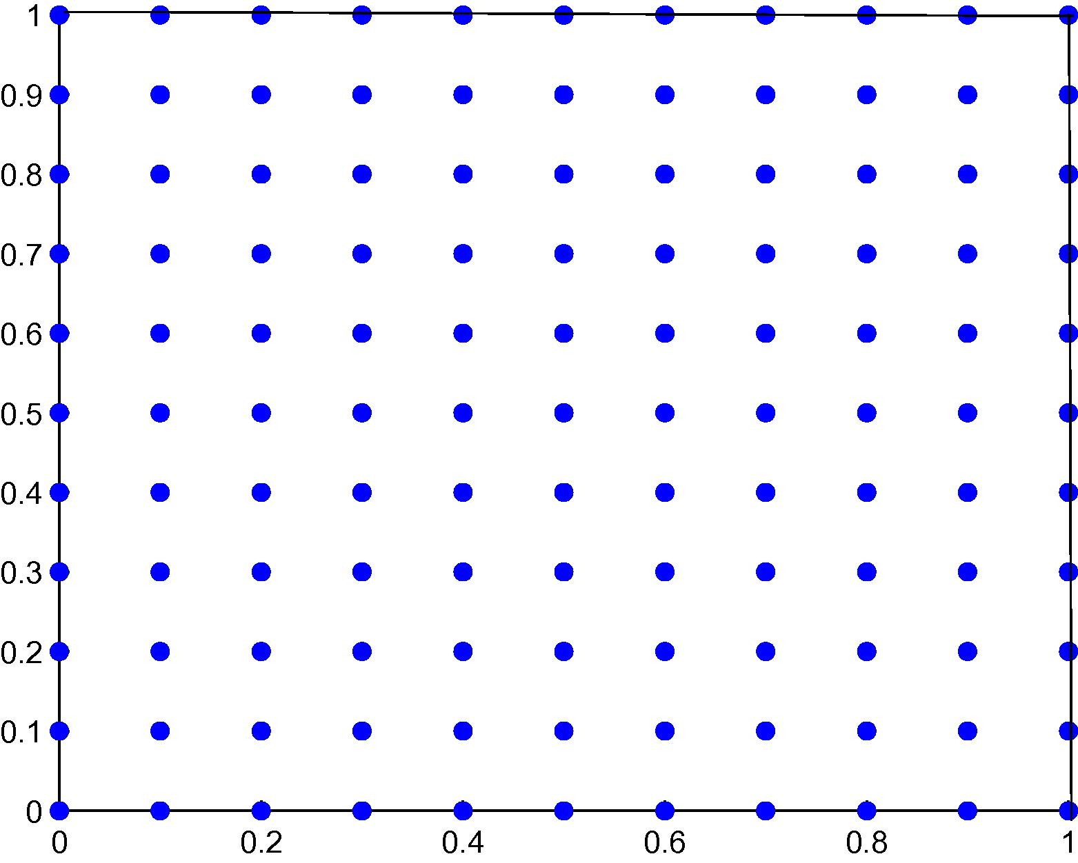
Nodal distribution in the square plate with 11 × 11 regular scattered nodes.
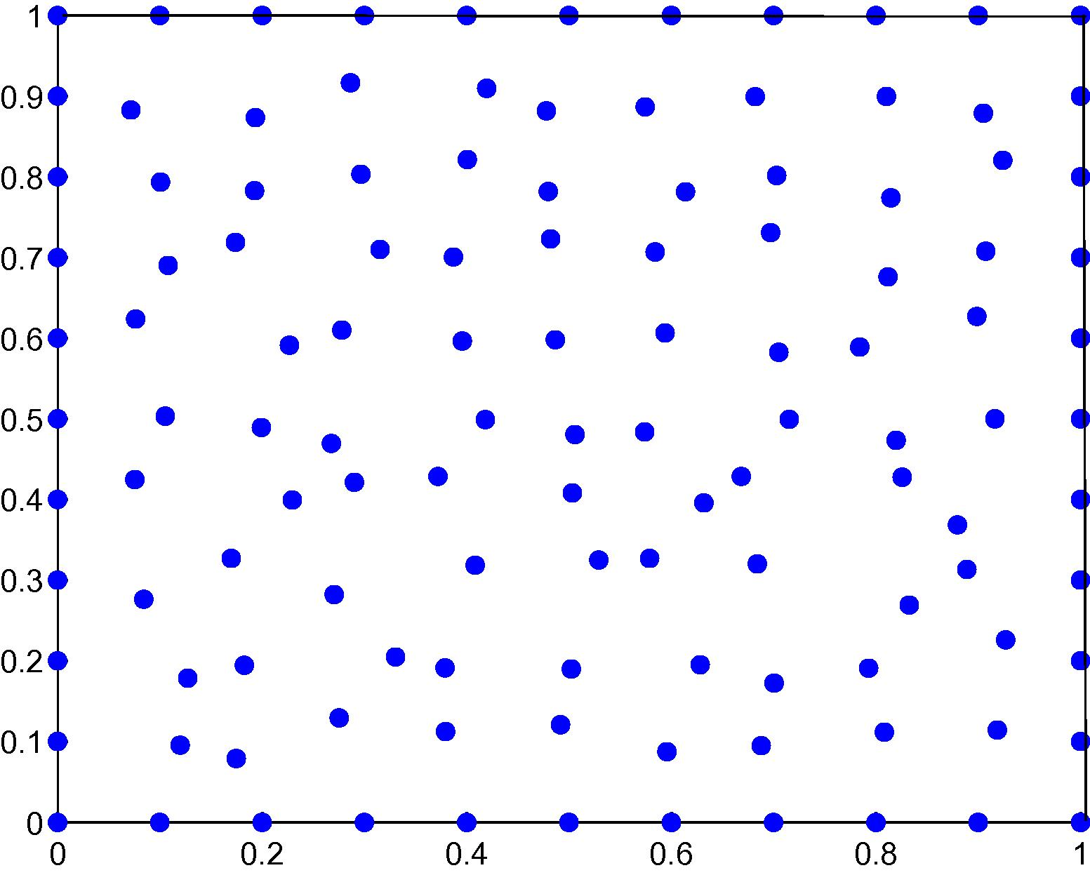
Nodal distribution in the square plate with 121 irregular scattered nodes.
For numerical implementation, selected a simply supported rectangular plate under sinusoidal load, uniformly distributed load, hydrostatic load and a hollow plate are implemented as follow:
4.1 Sinusoidal load on a simply supported rectangular plate
An exact solution in term of deflection is given by Timoshenko and Woinowsky-Krieger (1959).
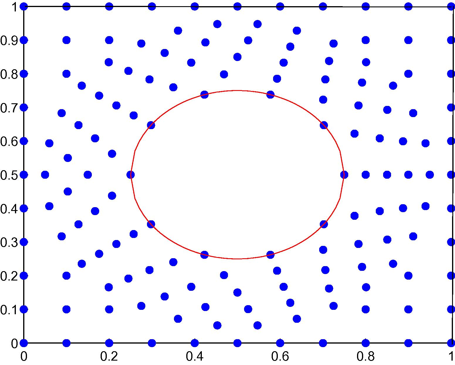
Nodal distribution in the hollow plate with 152 irregular scattered nodes.
For both the errors caused by introducing two-filed variables of this method, tabular errors using linear basis for selected number of nodal points of Example 4.1 are shown in Table 1 while Table 2 shows the errors using quadratic basis instead. According to both tables, these results show the convergence of this method by increasing the number of nodal points which can be see as an increasing accuracy by increasing the number of nodal points. In addition, illustratively, the fictitious values w versus exact solution and absolute value of the difference between exact solution and approximate solutionis are shown in Fig. 4 while the results of absolute maximum relative errors and root mean square relative errors are shown in Figs. 5 and 6, respectively.
n
16
0.087161168170710
0.043580584085307
25
0.050358497618669
0.030113754701725
36
0.032361053913413
0.021484740518138
49
0.023035676208513
0.016387047401505
64
0.017143934984936
0.012673300080537
81
0.013492037450895
0.010323479185026
100
0.010879139865142
0.008417391483891
121
0.002336287440439
0.001632271994812
n
16
0.091657933473486
0.045828966736731
25
0.050623969866327
0.030352930169516
36
0.031908920567838
0.021037079186475
49
0.022606591744903
0.015987485213218
64
0.016482360093915
0.012121872348316
81
0.012806666014302
0.009807325440163
100
0.010070455041601
0.007871532231840
121
0.001516655001101
0.001107414913633
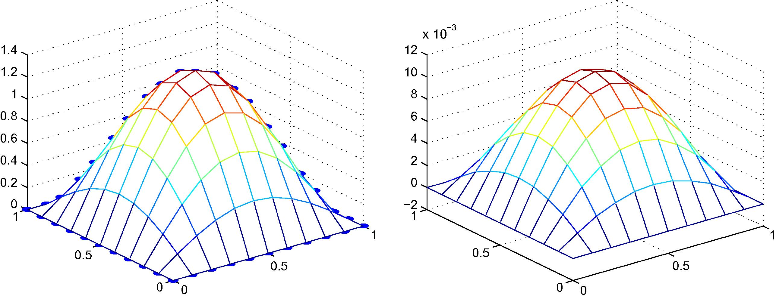
Exact solution versus fictitious values (left) and absolute value of the difference between exact solution and approximate solution (right) of Example 4.1, 11 × 11 regular nodal distribution with linear polynomial basis.
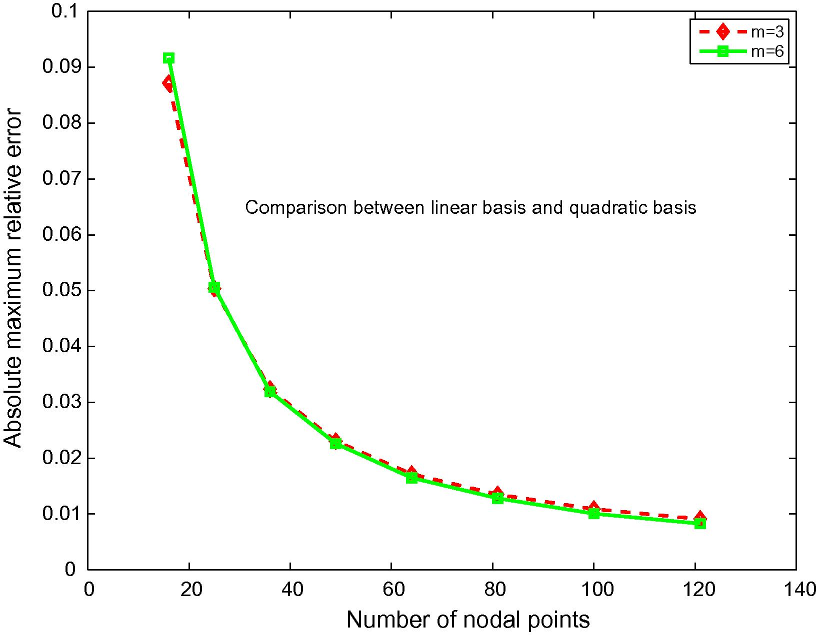
Maximum relative errors as a function of nodal points of Example 4.1.
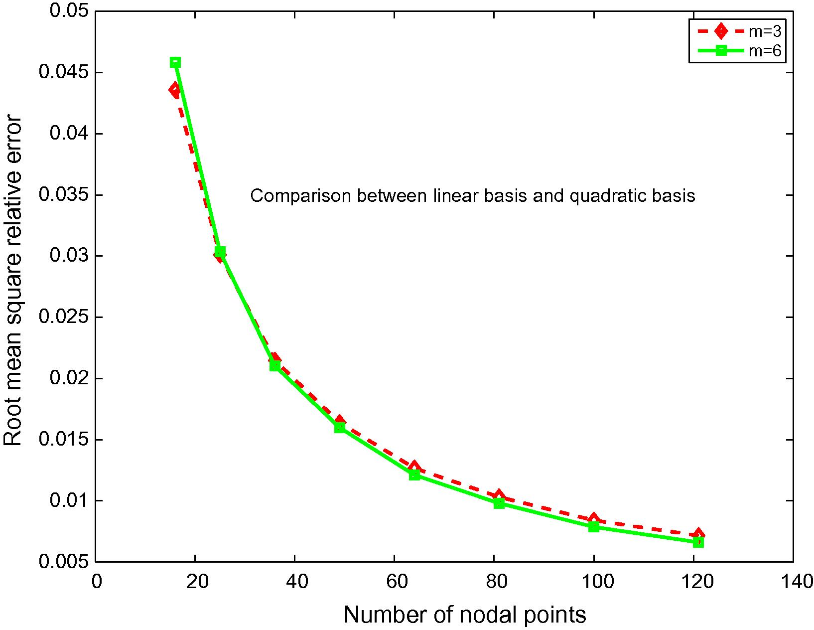
Root mean square relative errors as a function of nodal points of Example 4.1.
4.2 Uniformly distributed load on a simply supported rectangular plate
An exact solution in term of deflection is given by Timoshenko and Woinowsky-Krieger (1959)
Likewise, for both of errors caused by introducing two-filed variables of this method, tabular errors using linear basis for selected number of nodal points of Example 4.2 are shown in Table 3 while Table 4 are shown the errors using quadratic basis instead. According to both tables, These results show the convergence of this method by increasing the number of nodal points which can be see as increasing accuracy by increasing the number of nodal points. In addition, illustratively, the fictitious values w versus exact solution and absolute value of the difference between exact solution and approximate solutionis are shown in Fig. 7 while the results of absolute maximum relative errors and root mean square relative errors are shown in Figs. 8 and 9, respectively.
n
16
0.009380370258943
0.004690185129419
25
0.010227433424274
0.004485160943519
36
0.009239014511950
0.003682568495845
49
0.008370612949564
0.003184019437063
64
0.006690798478377
0.002493855584604
81
0.005456953335600
0.002188658062610
100
0.003647844775999
0.001742330978038
121
0.002669141979986
0.001031499111947
n
16
0.014260294100857
0.007130147050416
25
0.014090587400685
0.006303146486460
36
0.009092940658449
0.003601777152419
49
0.008382851789990
0.003165358484080
64
0.005693541722870
0.002058154266352
81
0.004422561209010
0.001764431690954
100
0.002573194839596
0.001215442051533
121
0.001853860804109
0.000639748726227
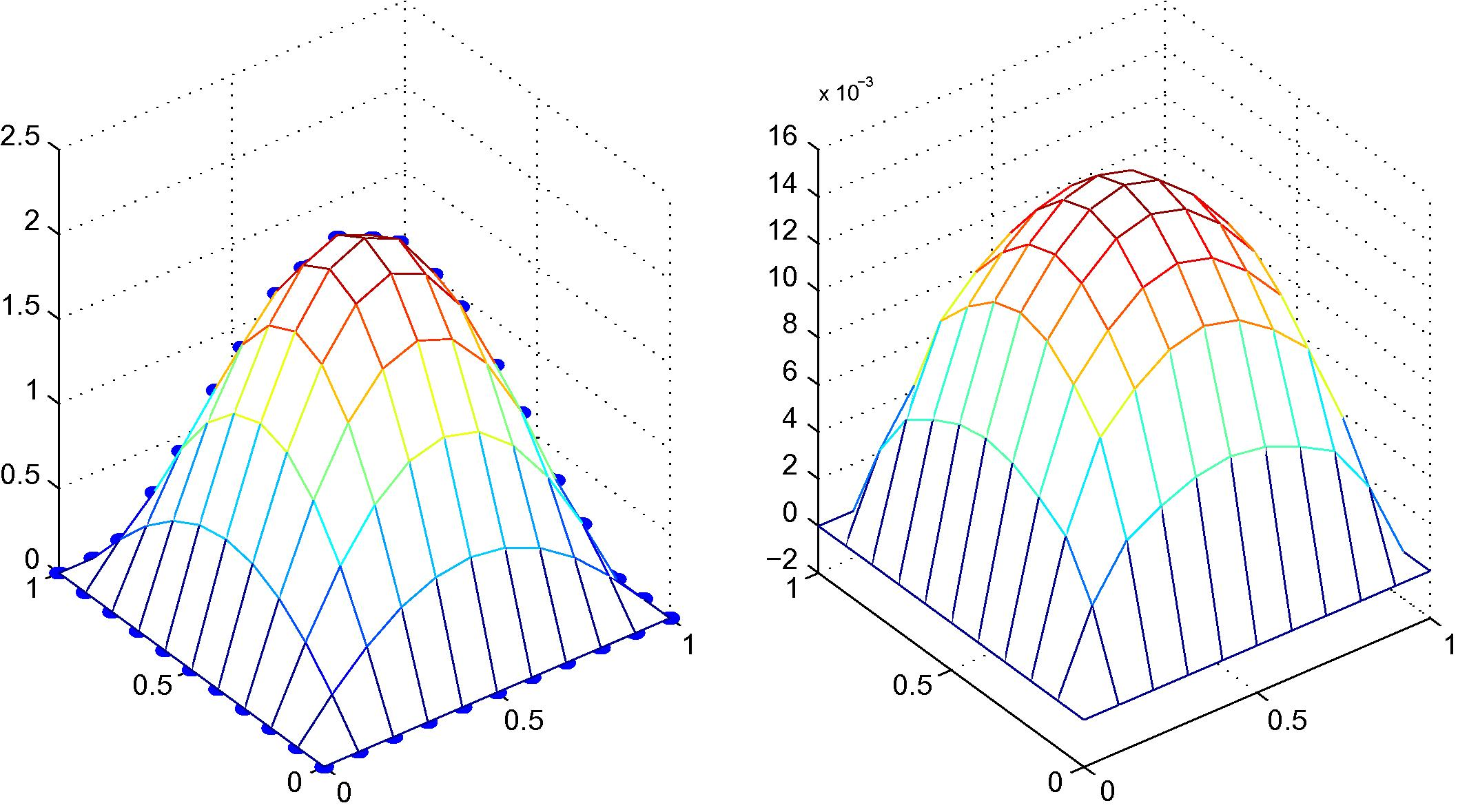
Exact solution versus fictitious values (left) and absolute value of the difference between exact solution and approximate solution (right) of Example 4.3, 11 × 11 regular nodal distribution with quadratic polynomial basis.
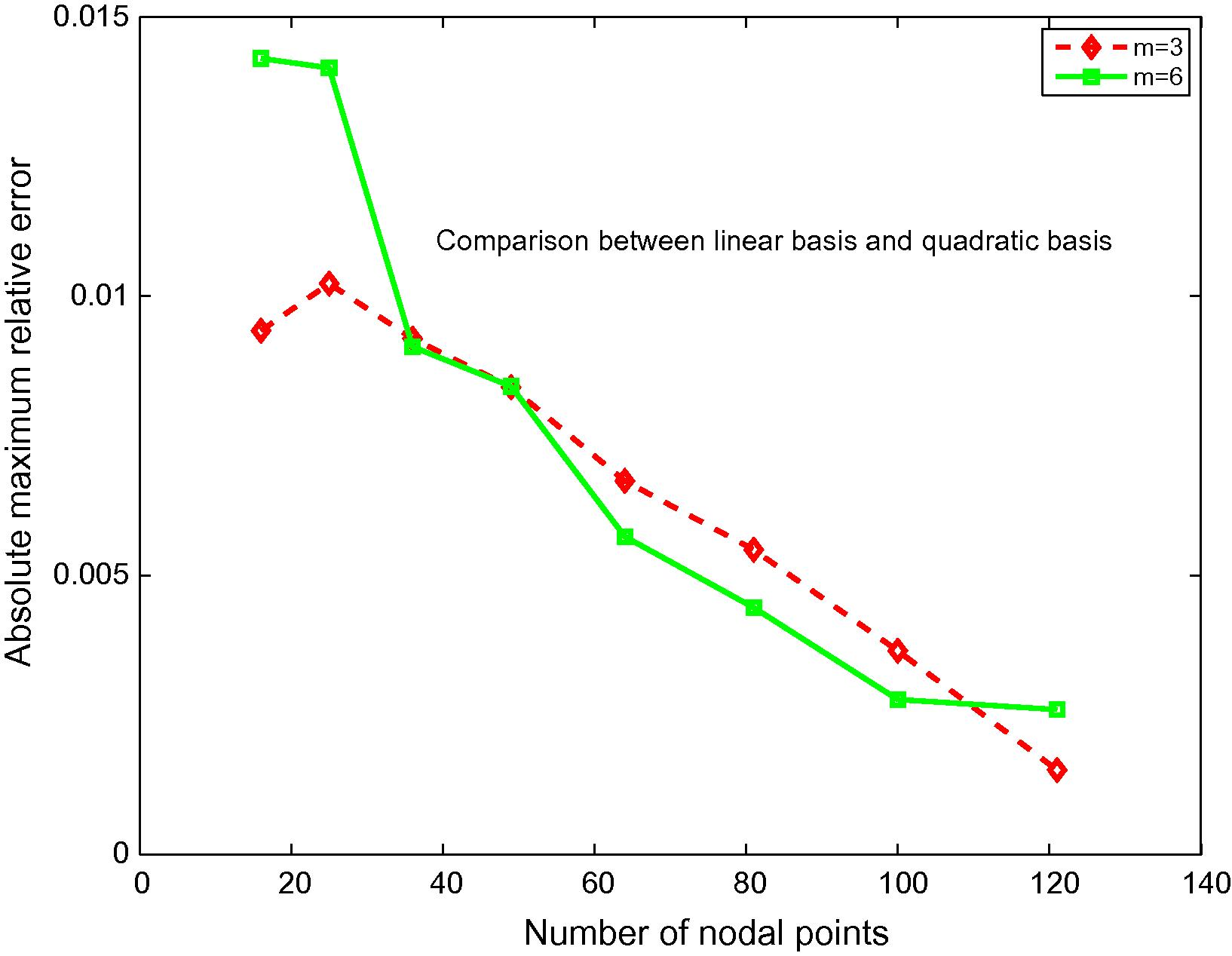
Maximum relative errors as a function of nodal points of Example 4.2.
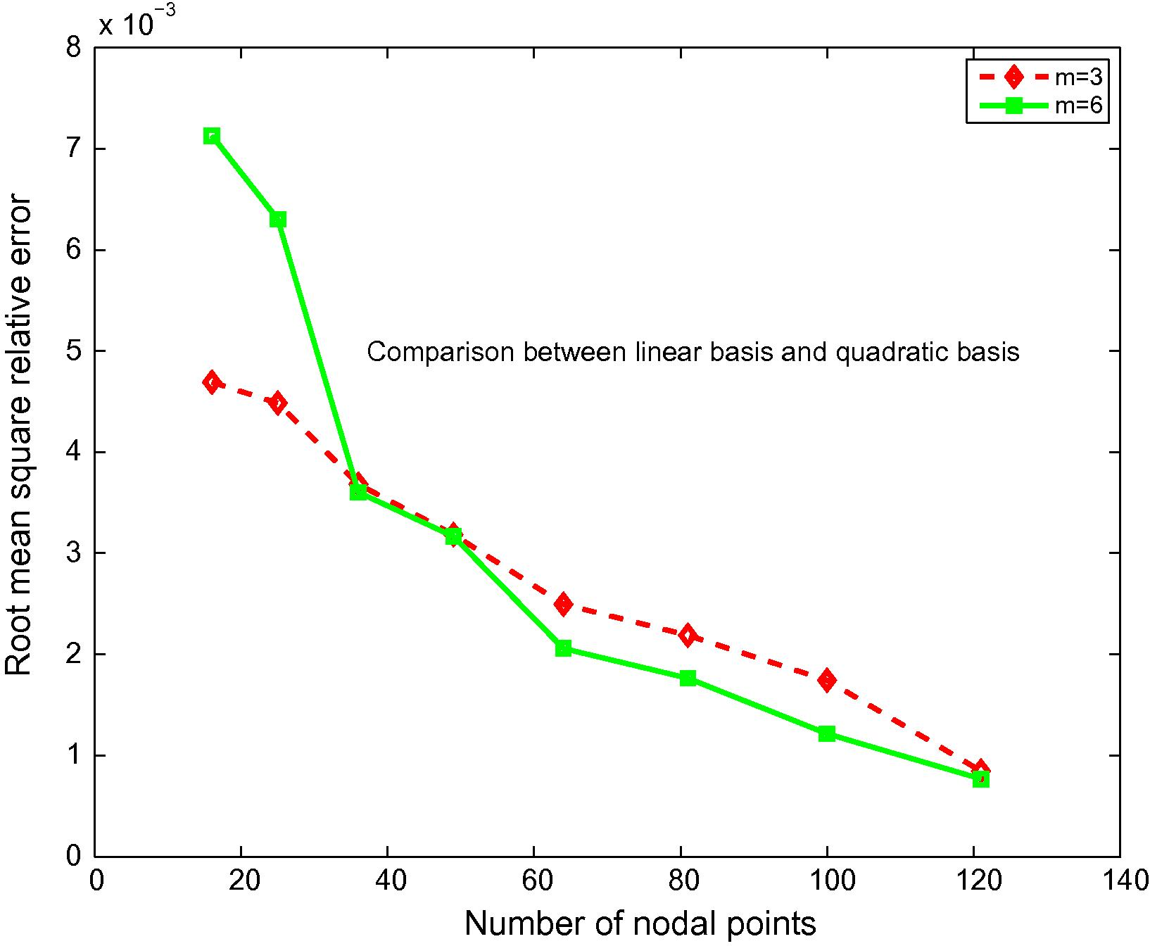
Root mean square relative errors as a function of nodal points of Example 4.2.
4.3 Hydrostatic load on a simply supported rectangular plate
An exact solution in terms of deflection is given by Rudolph (1974)
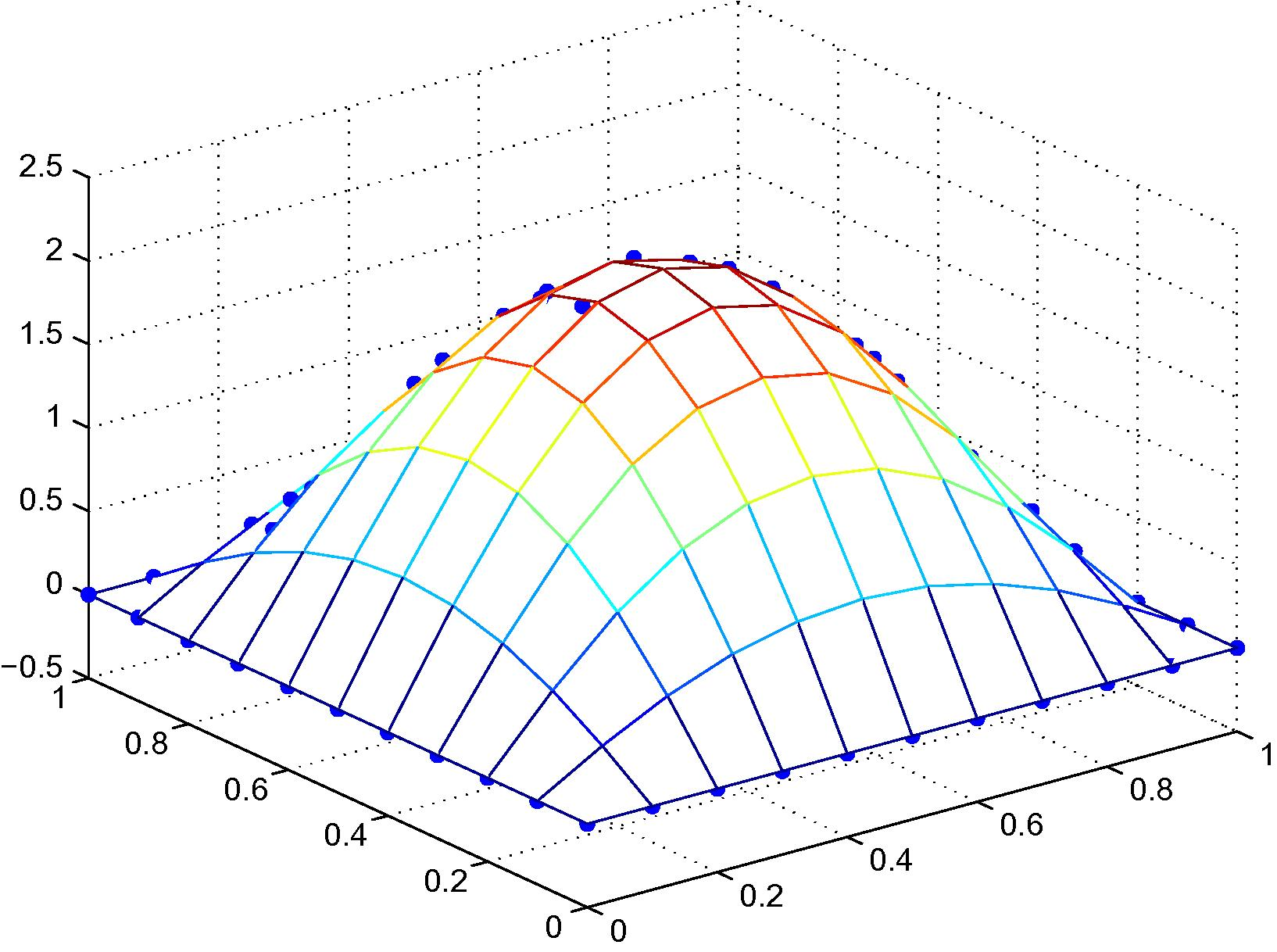
Exact solution versus fictitious values of Example 4.3, 121 irregular nodal distribution with linear polynomial basis.
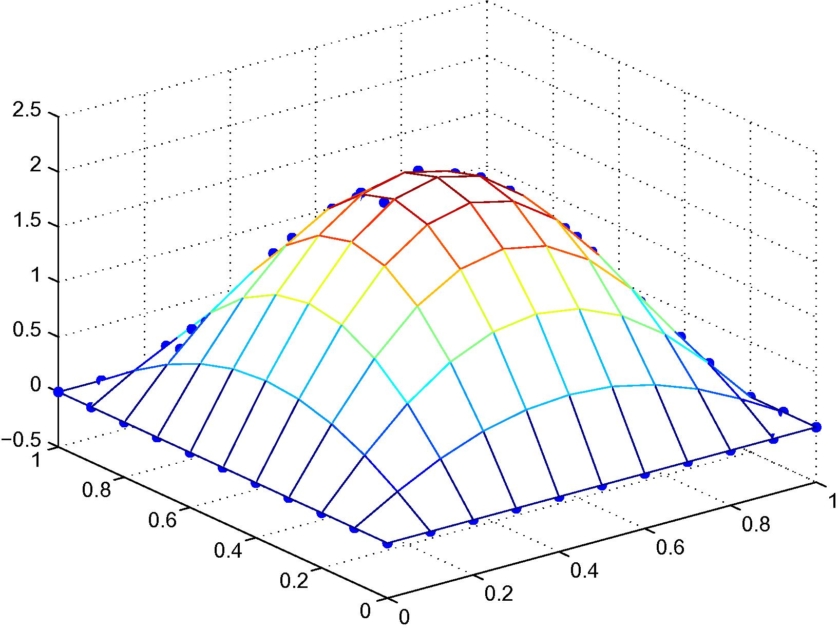
Exact solution versus fictitious values of Example 4.3, 121 irregular nodal distribution with quadratic polynomial basis.
4.4 A simply supported hollow plate
An exact solution in term of deflection is given by
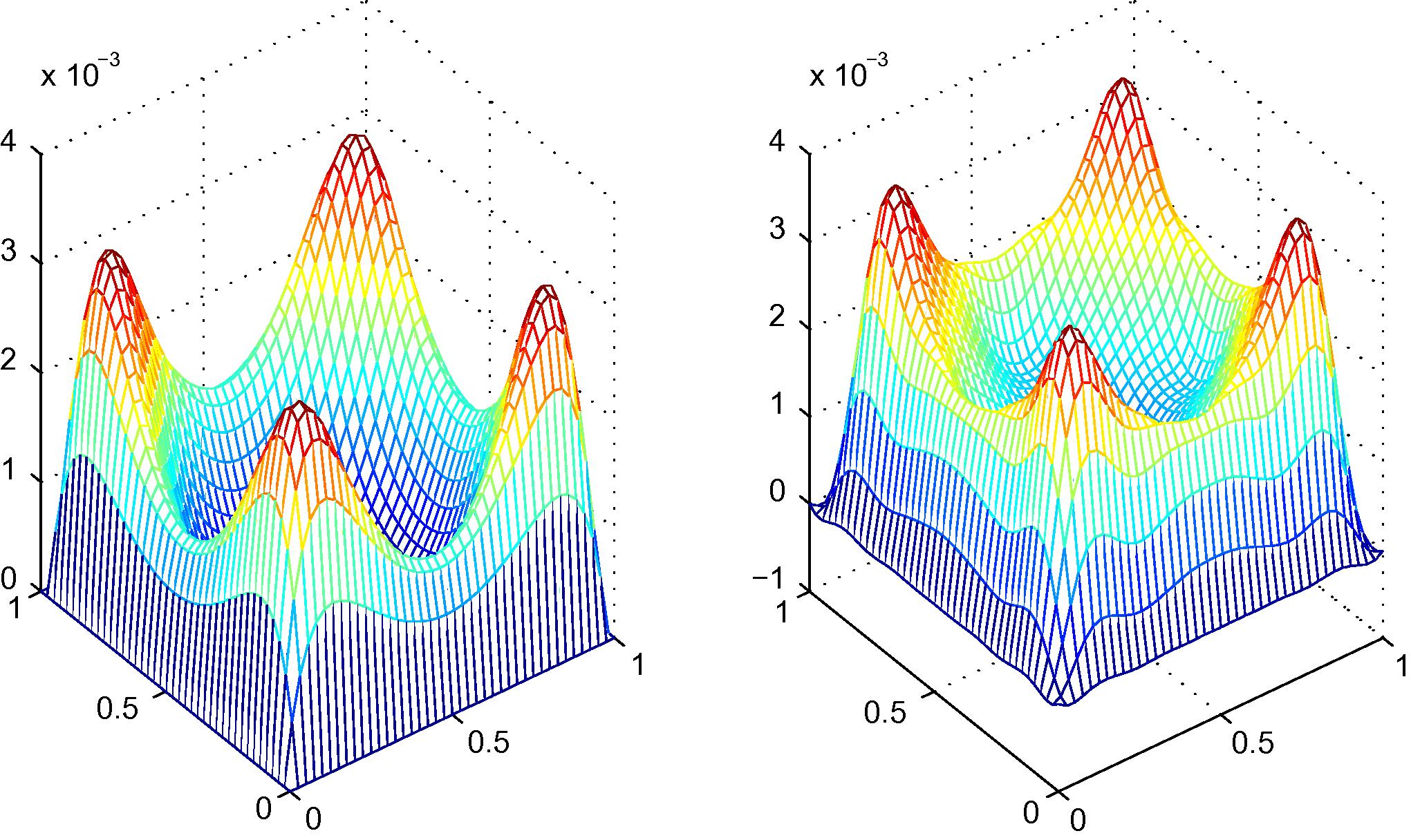
A comparison of an exact solution (left) and an approximate solution (right) of Example 4.4, 152 irregular nodal distribution with linear polynomial basis.
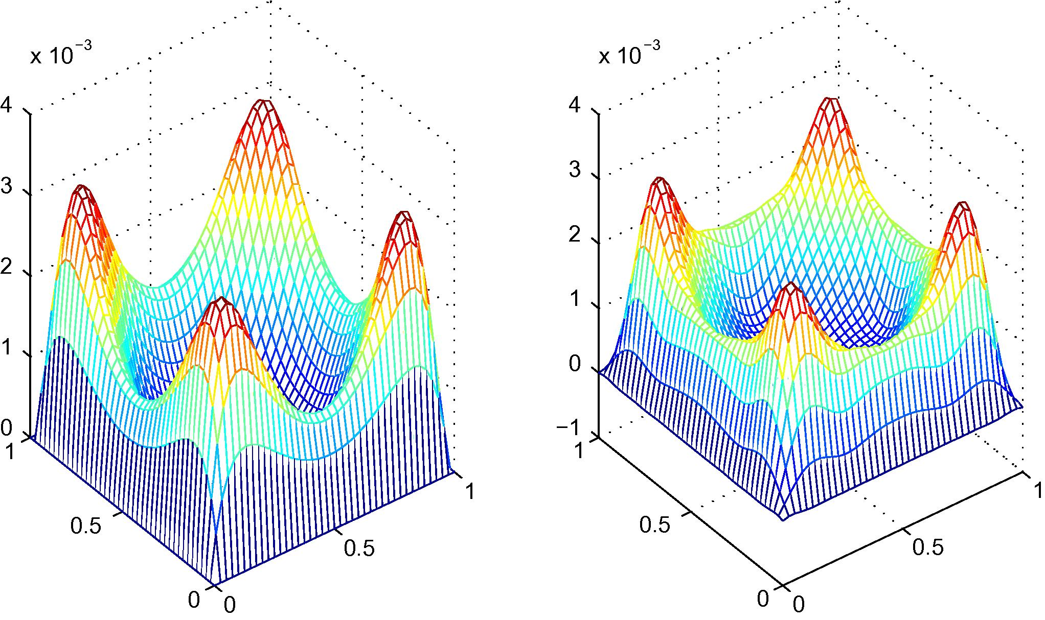
A comparison of an exact solution (left) and an approximate solution (right) of Example 4.4, 152 irregular nodal distribution with quadratic polynomial basis.
According to numerical results, both the errors using quadratic polynomial basis are less than both the errors using linear polynomial basis; moreover, increasing a number of nodal points can be decreased maximum relative errors and root mean square relative errors. Typically, quadratic-polynomial-basis usage is a better criterion constructing the nodal shape function than linear-polynomial-basis usage; furthermore, increasing a number of nodal points can decrease maximum relative errors and root mean square relative errors. Irregular nodal arrangement can also consider constructing shape function. It can be seen that the agreements between numerical and analytical results are quite excellent, and the convergence is very good as well as computational efficiency.
5 Conclusions
An alternative approach of meshless method for solving thin plates is presented in the present work. The moving kriging interpolation method can also be used for constructing nodal shape functions as well as two-field variables scheme and is proposed in order to decompose the biharmonic equation into a coupled of Poisson’s equations; furthermore, two-field variable local weak forms using Heaviside step function enable us to simplify the complicated conventional local weak form of the biharmonic equation as well as impose straightforward the simply supported boundary condition, For these reasons, computer literacy is also conducted systematically in the sense of easiness and robustness and its implementation is also acceptable as well. Comparing between exact solution and approximate solution for all examples, numerical results shows that usage of the quadratic polynomial and linear basis can give quite accurate numerical results.
Acknowledgments
The authors would like to thank the Department of Mathematics, KMUTT, Thailand, for facilities during this research. Moreover, the authors would like to thank their parents and family, who have also been encouraging, as well as their friends for taking care of each other. Finally, the authors would like to thank the referees for their useful comments and language editing, which greatly improved the manuscript.
References
- Large deflection analysis of flexible plates by the meshless finite point method. Thin Wall. Struct.. 2010;48:200-214.
- [Google Scholar]
- Performance of the MLPG method for static shakedown analysis for bounded kinematic hardening structures. Eur. J. Mech. A Solids. 2011;30:183-194.
- [Google Scholar]
- Dynamic elastoplastic analysis using the meshless local natural neighbour interpolation method. Int. J. Comput. Methods. 2011;8(3):463-481.
- [Google Scholar]
- A truly boundary-only meshfree method applied to Kirchhoff plate bending problems. Adv. Appl. Math. Mech.. 2009;1:757-763.
- [Google Scholar]
- Winkler plate bending problems by a truly boundary-only boundary particle method. Comput. Mech.. 2009;44:341-352.
- [Google Scholar]
- Analysis of thin plates by the element-free Galerkin method. Comput. Mech.. 1995;17:26-35.
- [Google Scholar]
- A meshless method for Kirchhoff plate bending problems. Int. J. Numer. Methods Eng.. 2001;52:1107-1130.
- [Google Scholar]
- A locking-free meshless local Petrov–Galerkin formulation for thick and thin plates. Int. J. Comput. Phys.. 2005;208:116-117.
- [Google Scholar]
- A meshless model for transient heat conduction analyses of 3D axisymmetric functionally graded solids. Chin. Phys. B. 2013;22(12):120204.
- [Google Scholar]
- Moving kriging interpolation and element-free Galerkin method. Int. J. Numer. Methods Eng.. 2003;56:1-11.
- [Google Scholar]
- Identities for the fundamental solution of thin plate bending problems and the nonuniqueness of the hypersingular BIE solution. Eng. Anal. Bound. Elem.. 2013;37:594-602.
- [Google Scholar]
- meshfree local Petrov–Galerkin method for solving the bending problem of a thin plate. Comput. Model. Eng. Sci.. 2002;3:53-63.
- [Google Scholar]
- Theory and Analysis of Plates. New Jersey: Prentice-Hall; 1974.
- Meshless formulations for simply supported and clamped plate problems. Int. J. Numer. Methods Eng.. 2002;55:359-375.
- [Google Scholar]
- Meshless local boundary integral equation method for simply supported and clamped plates resting on elastic foundation. Comput. Methods Appl. Mech. Eng.. 2002;191:5943-5959.
- [Google Scholar]
- Physical decomposition of thin plate bending problems and their by mesh-free methods. Eng. Anal. Bound. Elem.. 2013;37:348-365.
- [Google Scholar]
- Theory of Plates and Shells. New York: McGraw-Hill; 1959.
- A local integral equation formulation based on moving kriging interpolation for solving coupled nonlinear reaction–diffusion equations. Adv. Math. Phys.. 2014;2014(7) Article ID 196041
- [CrossRef] [Google Scholar]


